Quick Installation Guide
00825-0100-4750, Rev BA
June 2009
Rosemount 8750WA
10
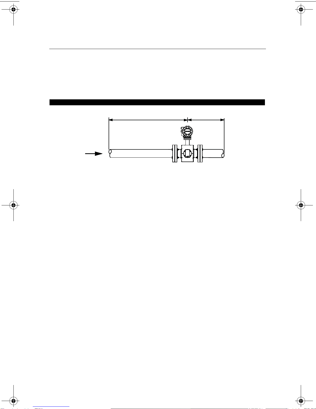
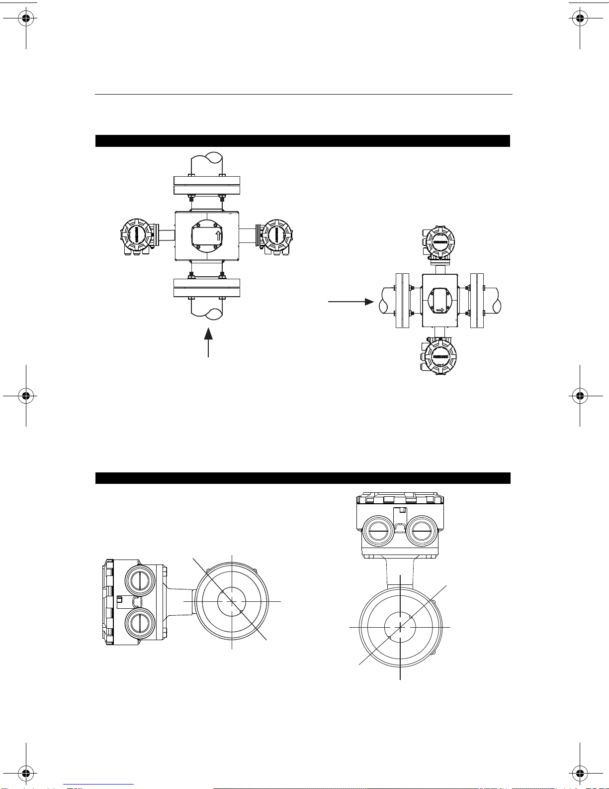
Wafer Sensors
Gaskets
The sensor requires a gasket at each of its connections to adjacent devices or piping. The gasket
material selected must be compatible with the process fluid and operating conditions. Metallic or
spiral-wound gaskets can damage the liner. Gaskets are required on each side of a
grounding ring.
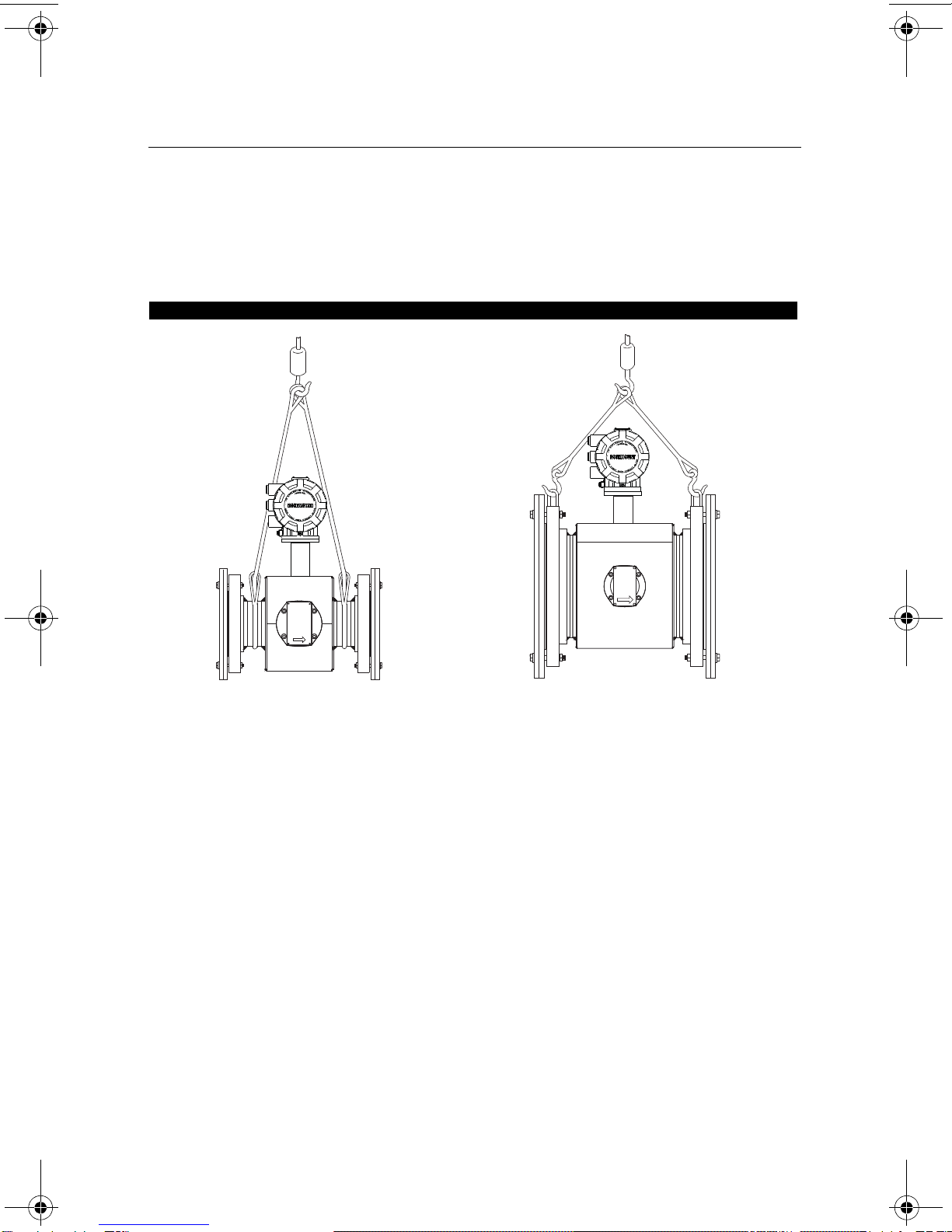
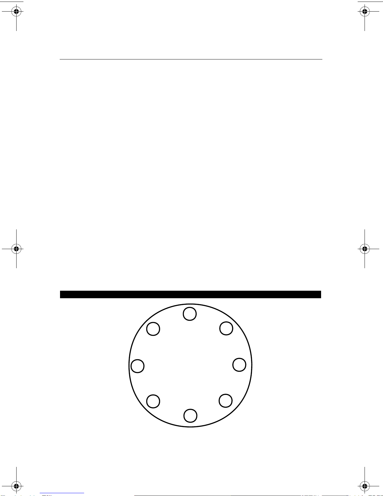
Alignment and Bolting
1. On 1.5 - through 8-inch (40 through 200 mm) line sizes. Rosemount strongly
recommends ordering the centering rings to insure proper centering of the sensor
between the process flanges. Place the alignment rings over each end of the sensor.
The smaller line sizes, 0.5 and 1 in. (15 and 25 mm), do not require centering rings.
2. Insert studs for the bottom side of the sensor between the pipe flanges. Stud
specifications are listed in Table 2.
NOTE
Using carbon steel bolts on smaller line sizes, 0.5 and 1 in. (15 and 25 mm), rather than the
required stainless steel bolts, will degrade performance.
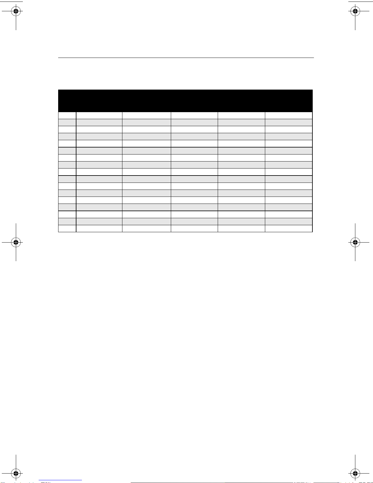
Table 1. Suggested Flange Bolt Torque Values for Rosemount 8750WA Flanged Sensors
PTFE Polyurethane/Neoprene liner
Size
Code Line Size Class 150
(pound-feet) Class 300
(pound-feet) Class 150
(pound-feet) Class 300
(pound-feet)
005 0.5 inch (15 mm) 8 8 - -
010 1 inch (25 mm) 812 - -
015 1.5 inch (40 mm) 13 25 7 18
020 2 inch (50 mm) 19 17 14 11
030 3 inch (80 mm) 34 35 23 23
040 4 inch (100 mm) 26 50 17 32
060 6 inch (150mm) 45 50 30 37
080 8 inch (200 mm) 60 82 42 55
100 10 inch (250 mm) 55 80 40 70
120 12 inch (300 mm) 65 125 55 105
140 14 inch (350 mm) 85 110 70 95
160 16 inch (400 mm) 85 160 65 140
180 18 inch (450 mm) 120 170 95 150
200 20 inch (500 mm) 110 175 90 150
240 24 inch (600 mm) 165 280 140 250
300 30 inch (750 mm) 195 415 165 375
360 36 inch (900 mm) 280 575 245 525
4750RevBAQIG.fm Page 10 Thursday, July 16, 2009 3:52 PM