3
6
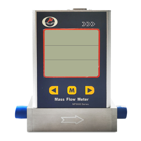
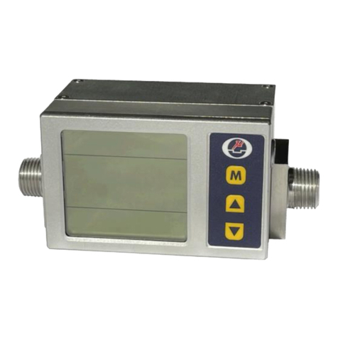
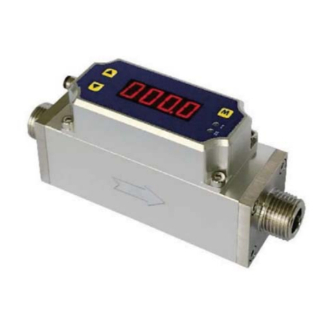
Siargo's proprietary MF series MEMS mass flow sensor technology provides accurate in-line flow
measurement with the availability of customer-specified packages. The sensor is manufactured using
Siargo's unique MEMS process that ensures high reliability. The sensors can measure air flow as low as
0.01m/sec and as high as 75m/sec. Depending on the applications, the sensors can be used to measure mass
flow, volume flow or media flow speed. The specially designed circuit provides amplification as well as
small signal processing capability that yields a high accuracy.
Siargo's flow sensors utilize the same thermal mass flow technology using energy balance design. But
unlike the other MEMS flow sensing technologies, Siargo's flow sensors have multiple sensors integrated
on a single silicon chip. The surface of the chip is passivated by ceramic materials with high thermal
conductivity to ensure the sensor's sensitivity. It also enhances the reliability by avoiding the direct
contact among the sensors and the flow media. Also, Siargo's sensor design makes it easy to package the
sensor in a variety of ways, which significantly expands the applications of the technology.
1. Overview
1.1 Siargo's MEMS Thermal Mass Flow Sensor Technology
1.2 Working Principle
Siargo's proprietary flow meter can measure gas flow in large pipes. The MEMS flow sensors are
integrated with a micro heater, local temperature sensors and environmental temperature sensor onto a
single chip. If no flow media passes through the MEMS sensor chip, a stable temperature field
(distribution) around the micro heater is maintained. When the flow media passes through the sensor chip,
the temperature field will be forced to change as the flow media will carry away the heat causing the
redistribution and variation of local temperature. Such a change of the local temperature will depend on
the media's mass as well as the media's flow speed. The sensors integrated on the silicon chip will then
measure such temperature redistribution, and the carefully designed signal process circuits and the
algorithm provided by the smart control software can then precisely measure the actual media mass flow
speed. This mass flow speed can then be translated into volume speed as well as accumulated volume
media consumption.
For the gas metrology using mechanical meters, the volume flow rate is adopted. The volume
rate nevertheless may not be a good indicator at industrial processing technology as the
processing gas quality depends vastly on the mass, not on the volume. In addition, the
volume of gas will change with different environment temperature and pressure. With the
MEMS thermal mass flow meter, it is possible to measure the "quality" (mass) of the gas
directly, and at real time. The mass flow rate will not depend on temperature and pressure.
Therefore an accurate measurement of the actual mass consumption becomes a reality. In
addition, the conversion of the mass rate to the volume rate is readily available by
o
referencing a standard condition such as 20 C and 101.325 kPa.
1.3 Volume Flow vs. Mass Flow
The installation must observe the following steps:
1. Make sure there are no any foreign materials in the pipeline.
2. Make sure there the seal gaskets are properly placed without interfering with the flow channel.
3. Connect the meter/sensor to the pipeline using proper tools to fasten the screws.
4. Initialization after power on, the display should show:
AUTO CHECKING
1) CRYSTAL OK
2) ADC OK
3) EEPROM OK
4) RTC OK
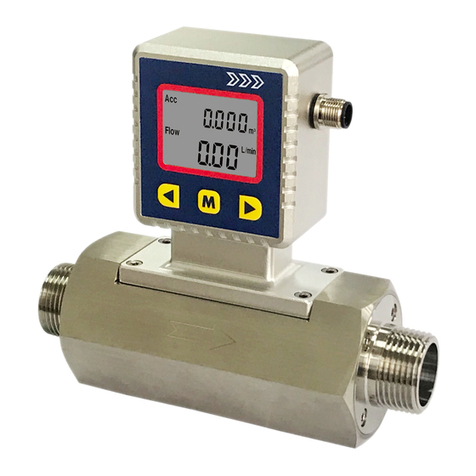
5. After initialization, the LCD will display Mass flow in the upper row and accumulated mass flow
On ly f or MF5000(e )
(ACC.) in the lower row.
Note: because this flow meter is highly sensitive, only when the pipeline has absolutely no flow,
the display will be zero. To ensure the offset is working properly, make sure the pipeline has NO
flow.
6.Offset detection.
For certain models, when apply to gases different from the calibration gas, proper reset of the offset is
necessary for the meter to work. In this case,
Open upstream and downstream valves, make sure the gas (to be measured) is fully filled into the meter
and any other gases have been completely replaced. Wait for about 30 sec, close all of the valves,
initializing the meter using the Siargo Gas Meter User Interface software or the handheld device (provided
separately, please contact manufacturer for details), to reset the offset.
On ly f or MF5000(e )
3.3 Cautions for the Installation
a). Welding the pipe while the meter is installed is prohibited;
b). Any foreign materials in the pipeline after installation may cause irreversible damage;
c). Seal gaskets must not block flow channel otherwise accuracy cannot be maintained;
d). The meter should be properly grounded via the electrical connection;
e). After installation, severe force applied to the meter may cause damage;
f). Severe vibration or very strong magnetic field may cause malfunction;
3.4 RS485 Data Communication Protocol
For purposes of computer control and networking, the RS485 is used for communication with the following
preferred settings:
Baud rate (Bits per second): 9600
Date bits: 8
Stop bits: 1
Parity: None
Flow control: None
Operation Mode
i). Send 0x9d to the meter and return with 0x9d;
ii). Send 0x54 to the meter and return with 0x54;
The interval time between two bytes sent to the sensor must be longer than 5ms;
The sensor will be at Operation Mode at which the data from the meter will be sent via RS485 in an
interval of one second.
The data are in the following format:
S=vvvvv\nF=ffffff\nA=aaaaaaaa\n;\n
V=vvvvv Voltage code;
F=ffffff Mass flow rate (Equal to fff.fff SLPM);
A=aaaaaaaaaaa Accumulated flow (Equal to aaaaaaaa.aaa SL).
User Mode:
i). Send 0x9d to the meter and return with 0x9d;
ii). Send 0x00 to the meter and return with 0x00;
The interval time between two bytes sent to the sensor must be longer than 5ms;
Then the sensor will be at User Mode at which the data will not be sent via RS485 by the meter.
:
www.Siargo.com www.Siargo.com
MF5000 Series User Manual (VB.4)MF5000 Series User Manual (VB.4)


