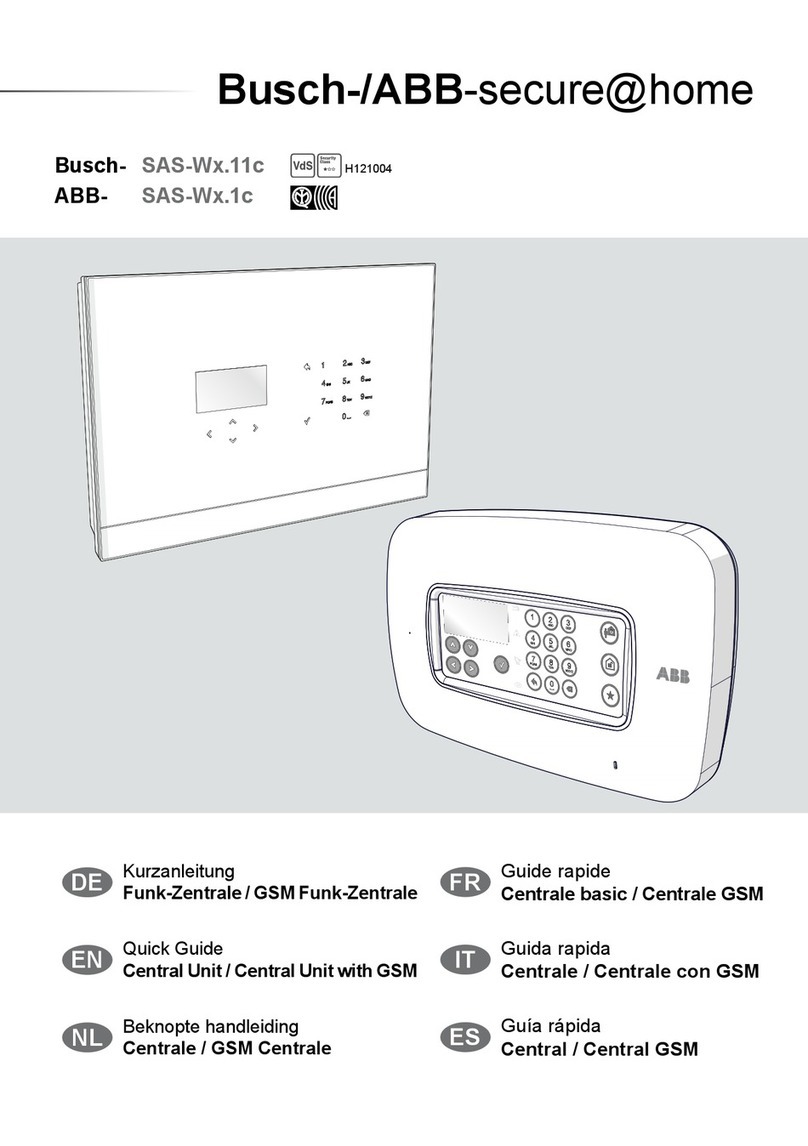
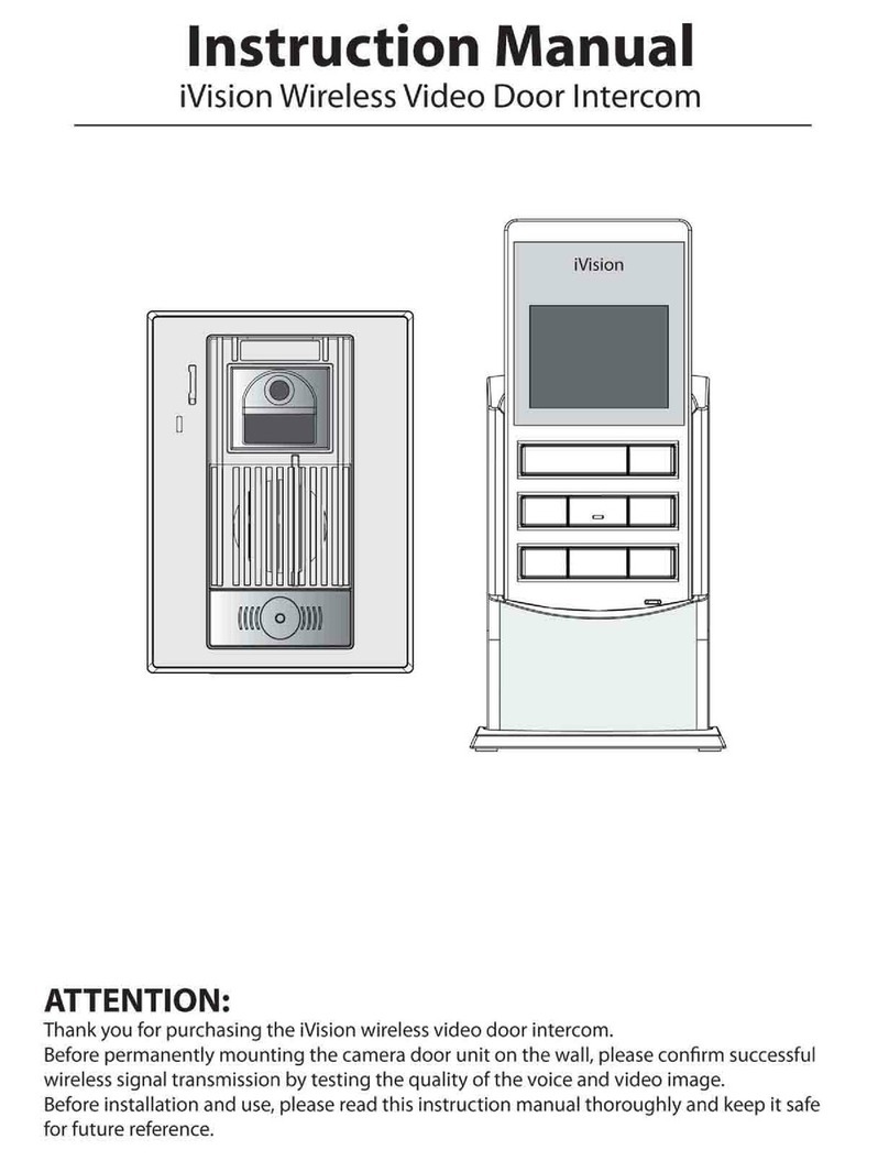
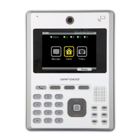
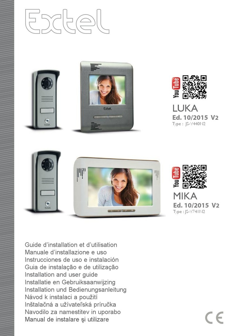
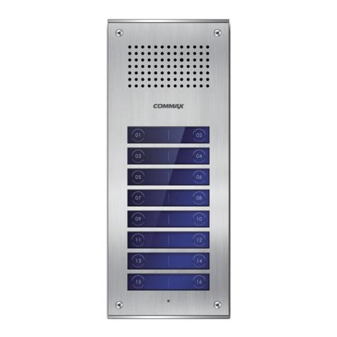
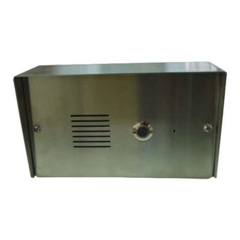
BRASH IMPORTS 7486DWL User manual

BRASH IMPORTS
DIGITAL WIRELESS
VIDEO DOOR PHONE SYSTEM
MODEL: 7486DWL,7130DWL,7310 DWL
I.CAUTIONS.............................................................................................................................................................. 2
II.PACKING LIST...................................................................................................................................................... 2
III.SYSTEM FEATURES ........................................................................................................................................... 3
IV.USER INSTRUCTIONS ....................................................................................................................................... 3
V.SYSTEM SETUP.................................................................................................................................................... 2
VI.SYSTEM INSTALLATION .................................................................................................................................... 4
VII.SPECIFICATIONS............................................................................................................................................... 6
www.brashimports.com.au

2/7
I.CAUTIONS
1. Shock Hazard--to prevent fire or shock hazard, do not expose the unit to rain, moisture or other liquid and do not
overload the power cord.
2. Instructions--Read and keep the instructions-all safety and operating instructions should be read and followed before
theunitisoperated
3. Power Sources -- This equipment should be operated only from the type of power source indicated on the marking
label and the power cord protection is needed.
4. Servicing and Replacement of Parts -- Do not attempt to service this product or replace any part inside by yourself
as opening or removing covers may expose you to dangerous voltage or other hazards. Refer all servicing to qualified
service personnel.
5. Lightning -- For added protection for this product before a lightning storm, or when it is left unattached and unused
for long periods of time, unplug it from the wall outlet and disconnect the cable system. This will prevent damage to the
product due to lightning and power-line, telephone-line, RF cable and Actuator/Polarization surge protectors to protect your
system from possible damage.
6. Move with Care-- This product is easy for damage, care for it during transportation, storage and installation.
II.PACKING LIST
(Image 1)
Standard
zMonitor 7486 DWL 1
zCamera United 7130 DWL 1
zCamera United Power Suuplier 7310 DWL 1
zMonitorCharger 1
zMonitorChargerPowerSupplier 1
zMannual 1
zAccessoryBag 1
z
2M 4
wire
cable 1
Monitor Alone :
zMonitor 7486 DWL 1
zMonitorCharger 1
zMonitor Charger Power Supplier 1
zMannual 1
Camera Unit Alone
zCamera United 7130 DWL 1
zCamera United Power Suuplier 7310 DWL 1
zMannual 1
zAccessoryBag 1
z2M4wirecable 1

3/7
III.SYSTEM FEATURES
1. Maximum 2 cameras and 2 monitors same time in a system.
2. Choosing 2.4G ISM digitalpublic frequnce resource:2402~2483.5MHz.
3. Transmitting at 20dBm,Receving -100dBm;
4. With 8~12 digital audio serial input, DAC output, 8K audio aquizition for good audio quality. And audio volue
presetable in 4 levels.
5. MJPEG digital video coding and decoding, 10~15 frames per second.
6. Reliable audio/video communication distance 150m in open area.
7. With AFH auto frenquncy jumping technology, working with 2.4G WIFI and blue tooth same time.
8. With auto sleeping mode, saving battery consumptions in stand by status.
9. With external power supplier for camera units DC3.6-6V, with this consideration, the lock can not be open from
outside camera unit, but signal from monitor.
10. Random 40 bit encryption for digital audio and video to secure the communicaton.
11. Random communication channel jumping and sychronization, no interferance from same products installed
nearby.
12. With communication, monitoring and remote lock opening functions.
13. Permitting monitor to monitor communication,like walki talki features.
14. Digital camera and digital 2.4 inch TFT LCD in the system for good image quality.
15. With self owned core technology, providing continioussoftware up grading without changs on hardware.
IV.USER INSTRUCTIONS
I). PRODUCT GUIDE
(Image 2)

1/7
1— Rain Shelter;
2— Working Indicator for Camera Unit (Blue
Color);
3— Microphone;
4— Camera;
5— Infrared Led;
6— Speaker;
7— Call Button;
8— Earphone Speaker;
9— Image Display LCD;
10— Monitoring On/Off Button ;
11— Brightness Setting Key;
12— Music Setting Key;
13— Monitor Working Indicator (Blue);
14— Microphone;
15— Door Release Button ;
16— Communication On/Off Button;
17— Audio Volume Setting Key;
18— Color Setting Key;
19— Desk Top Talking On/Off Button;
20— Battery Ready Indicator(Green); When
battery is in charged full, this indicator is constantly
On;
21— Battery Charging Indicator(Yellow):
When battery is in charge, this indicator is constantly
On;
22— Desk Top Talking Indicator(Red): When
a monitor placed on charger is called from camera
unit, this indicator is constantly On;
23— Handfree Talking Speaker;
24— Battery Cover;
25— DC Power Jack;
II). FUNCTIONS
1. VISITOR CALL
1). When a visitor presses the "Call” button on the outside camera unit to call the monitors, the camera unit will have
continous “DU-” “DU-”chime, and the called monitors sound “Call Music” with blue LED indicating the call and display
the visotor’s image on LCD.
(Image 3)(Image 4)
If the call is not connected with monitors within 4S, the camera unit will sound continous “DU-” “DU-” “DU-” “DU-”and
return to standby.
Upon viewing the monitor's LCD screen and the visitor'simage, you have two choices;
A. You can choose to "not respond"(by not pressing (ON/OFF)
b
utton, thecallwillbeendedin50S.
B. You can choose to "respond” by pressing (ON/OFF)button to start a voice communication.Each voice
communication last maximum 60S.
During the communication, you can press lock release button ( ) to release the lock or press (ON/OFF)to
end the call.

2/7
2. MONITORING
(图 5)(图 6)
Under standby status, you can press monitoring button ( ) to view the video from camera unit No 1, and press music
setting key to switch video from camera unit No 1 to No 2 if any. See above images. The monitoring time last 60S for
maximum.
3. MONITOR CALLMONITOR
(Image 7)
Under standby status, you can press (ON/OFF)button to call another monitor if any. If the other monitor receive the signal
and response by pressing (ON/OFF)button, a voice communication is established. This communication last 60S for
maximum.
V.SYSTEM SETUP
1). CODING PROCESS
If your system has only one monitor and one camera unit, you do not need coding process. The IDs have been existing with
monitor and camera unit before ex-factory. This process is only needed for following cases:
1. The units do not recognize each other under extremly rare circumstances, such as lightening;
2. You need to increase monitor or camera unit to exixting system.
Recoding for Existing Camera units and Monitor:
Step 1:Assume a monitor ( No 1 monitor for example) as the system master, press Brightness key and button
same time while in standby status until “Monitor Working Indicator”light up constantly , the master will be in
Coding status.
Step 2:Constantly press “CALL” button on camera unit until a “Di-”sound, the camera unit will be in coding status.
Step 3:With in 16seconds, if both monitor and camera unit sound “Di-” “Di-” “Di-”, that means coding success, the units
will return standby status automaticaly. If the coding fails, the both units only sound “Di-”, also return standby status
automaticaly.
ON/OFF BUTTON

3/7
Increase Monitor or Camera Unit:
Step 1:Press Brightness key and button same time while in standby status until “Monitor Working
Indicator”flicks , the master is ready to code the new devices to existing system.
Step 2:Press Brightness key and button on the 2nd monitor same time while in standby status until “Monitor
Working Indicator”flicks , the monitor is ready for coding to the existing system.
With in 16seconds, if the both monitors sound “Di-” “Di-” “Di-”, that means coding success, the monitors
will return standby status automaticaly. If the coding fails, the both monitors only sound “Di-”, also
return standby status automaticaly
Step 3; Constantly press “CALL” button on camera unit until a “Di-”sound while the master is in coding status. With in
16seconds, if both master and camera unit sound “Di-” “Di-” “Di-”, that means coding success, the units will
return standby status automaticaly. If the coding fails, the both units only sound “Di-”, also return standby
status automaticaly.
For security consideration, each camera unit only has one chance for coding !
(Image 8)(Image 9)
2). CALL MUSIC SETUP
.While the monitor is in standby status, if press the Music Setting Key for 3 seconds (image 10), you can start to select “Call
Music” by press button, there is a “Call Music”change each time you press button. You can press
confirm the “Call Music” by press “ON/OFF” button (Image 11). There are totally 12 optional musics stored in
monitor.
Image 10)(Image 11)
3). VOICE VOLUME SETUP
Lock Release
ON/OFF
Button

4/7
While the monitor is in Communication status, you can press “Voice Volume Setting Key” (Image
12) to set the monitor’s voice volume. The voice volume increases each level after one pressing,
but it will return to the lowest level after one pressing if the volue has been in the highest level.
The alteration cycle is: 1→4→1.
(Image 12)
4). BRIGHTNESS SETUP
While the monitor is in Communication status, you can press “Brightness Setting Key” (Image
13) to set the monitor’s display brightness. The brightness increases each level after one pressing,
but it will return to the lowest level after one pressing if the brightness has been in the highest
level. The alteration cycle is: 1→8→1.
5). COLOR SETUP
While the monitor is in Communication status, you can press “Color Setting Key” (Image 14) to
set the monitor’s display color. The color increases each level after one pressing, but it will return
to the lowest level after one pressing if the color has been in the highest level. The alteration cycle
is: 1→5 →1.
VI.SYSTEM INSTALLATION
1). MONITOR(S)
(Image 15)
There is no need for the installation for monitor(s), please start the monitor(s) according to following steps:
1. Insert battery(s) to the monitor(s) , Image15;
2. Put the monitor(s) on to the monitor chager(s);
3. Connect monitor charger(s) to AC power;
(Image 13)
(Image 14)

5/7
The monitor(s) will be functioning when the battery is charged properly.
2)CAMERA UNIT(S)
(Image 16)(Image 17)
Camera unit 7139DWL is a surgace mounting device. The installation steps are:
1. Choose a proper place on door or on side of door, that is about 145cm from the ground. Drill two ∮8mm holes with
depth more than 50mm. The two holes need to be lined verticaly and apart 100mm. Dill another ∮10mm through hole
in the mid of the two holes. see image16
2. Fix the rain shelter to the place with screws and screw insertions, see image 17;
3. Connect 2M 4-wire cable with camera units and let the other terminal of cable through the door or the wall, see image
17;
4. Insert camera unit into rain shelter and fix it with screw, see image17
5. Install power supplier 7310DWL, see image 21;
6. Connect the other terminal of 2M 4-wire cable with power supplier, see image18;
7. Connect power supplier with AC power point.
Notice:
1. Do not install camera units on or near metal door or metal wall;
2. Do not expose power supplier to rain or direct sun shine.
3. Observe the regulations for connecting AC power.
(Image 21)(Image 20)
3). WIRING

6/7
Terminal 1,2,3 of power supplier are for lock connection. Terminal 1 and 2 are used for 12V, NO (Normaly Open) locks,
say giving power to open, such as punchturing locks. Terminal 2 and 3 re used for 12V, NC (Normaly Closed) locks, say
breaking power to open, such as elcteo-maganetic locks.
Terminal 4,5,6,7 of power supplier connect to terminal 1,2,3,4of camera unit, the definitions are:VCC+5V, GND,
DATA+. DATA-.
(Image 22)
VII.SPECIFICATIONS
1. PRODUCTS
7486 DWL 7130 DWL 7310 DWL
Voltage Requirements 3.7-4.2V 4.8-5.2V
Input:100V—240V, 50 Hz / 60Hz
Output:1599mA, DC5V/12V
Current
Standby: 20mA,
Working: 300mA
Standby: 100 mA,
Working: 250mA
Connection Method Wireless Wireless 4 wire
Monitor Screen 2.4” TFT LCD
Camera 1/3” digital
Communication 2.4G ISM 2.4G ISM Serial Port
Call Tone 12 optional music
Communication Duration 60S 60S Continious
Communication Distance 150M in open area 150M in open area 10M
Operating Temperature -10--50℃-10--50℃-10--50℃
Storage Temperature -20--70℃-20--70℃-20--70℃
Weight 360G 385G 430G
Dimensions (mm) 17.x55x25mm 200x110x40mm 116x86x50mm

7/7
2.CHARGER ADAPTER
Input Power:AC100V~220V Frequency:50/60
Output:DC9V ±0.2V 1000mA
3.ACCESSORIES
Name Specifications Qty Application
Mannual 1
Screw Insertion 8mmX28mm 5 Fix rain shelter and power7310DWL
Screw 1 4mmX18mm 2 Fix rain shelter
Screw 2 4mmx40mm 3 Fix power 7310DWL
Screw 3 3mmX8mm 1 Fix camera unit to rain shelter
Connecting Cable 4wire 2.0M 1 Connect 7130DWL to 7310DWL
Battery 54mmX34mmX4.6mm, 3.6V, 600mAh 1 For Monitor(s)
This manual suits for next models
2
Table of contents
Other BRASH IMPORTS Intercom System manuals

