BrasilSat UDS71-09S User manual

Installation Instructions
UDS Antenna´s Family
With 90 cm Diameter

DESCRIPTION
The UDS antenna´s family are the Ultra High Performance antennas, operating in single polarization,
provided by Brasilsat Harald S/A. The antennas are designed for short-haul microwave systems in all
common frequency ranges from 7 GHz to 23 GHz. They are typically deployed in dense urban areas,
metropolitan and suburban locations, aggregation points. They are especially optimized to integrated
radios to reduce costs, installation complexity and time.
This Installation Instruction is valid for antennas in the following version:
• Antenna models: UDS71-09S; UDS107-09S; UDS144-09S; UDS177-09S and UDS212-09S
• Reflector Ø 90 cm;
• Single polarization;
• Standard mount for support pipe Ø 114 mm;
• Reflector aperture covered by a radome;
• The design allows a fine adjustment range of +-10° for elevation and +-15°for azimuth;
NOTE
This instruction must be read completely before starting the installation.
The installation/maintenance/removal need to be made by qualified personnel.
Brasilsat Harald S/A disclaims any responsibility for the result of improper and unsafe
installation.
The pole/tower/other structural element involved to support the complete antenna as
described in this instruction must be verified/approved by structural specialist in respect
to all the national/local regulation.
All the required tools/instruments must be available.
It is important to mount the antennas exactly as described in this document. Don’t use
any parts, screws/nuts, not included in the packaging or not recommended by the
supplier.
The Antenna system should be inspected once a year by qualified and experienced
personnel to verify proper installation/maintenance/condition of equipments.

- 3 -
INDEX
1Overview
......................................................................... 4
1.1 Well mounted Antenna’s Profile ....................................................... 4
1.2 Antenna’s Mounting Dimension ....................................................... 4
1.3 List of the mounting tools............................................................. 5
2Antenna installation
............................................................. 5
2.1 Open the shipping box, check the components according to the following list. ............... 5
2.2 Mounting steps ..................................................................... 6
2.2.1 Transfer Polarization............................................................... 6
2.2.2 Install panning system to the antenna ................................................ 7
2.2.3 Install Anti-slide corner bracket...................................................... 8
2.2.4 Lift the antenna to a tower .......................................................... 9
2.2.5 Install the antenna to the mounting pole .............................................. 9
2.2.6 Install articulated bolt assembly .................................................... 10
3Antenna adjustment
........................................................... 11
3.1 Azimuth adjustment ................................................................ 11
3.2 Elevation adjustment ............................................................... 12
3.3 Install side strut assembly ........................................................... 13
3.4 Install Anti-slide corner bracket component adjustment.................................. 14
4Pluck the plastic plug
.......................................................... 15
Attachment: Mechanical Torque ........................................................... 15
5Final check
...................................................................... 15

- 4 -
1 Overview
1.1
Well mounted Antenna’s Profile
Figure 1 - Antenna’s Profile Drawing
1.2
Antenna’s Mounting Dimension
Figure 2 - Antenna’s Dimension Drawing
- 5 -
1.3
List of the mounting tools
The installation tools are listed in Table 1.
Table 1 - List of the mounting tools
NO. Name Specification Quantity
1 Crowbar 1 pcs
2 Spanner S=8,13, 18, 21, 24 2 pcs
3 Allen Key S=5 1 pcs
4 Screwdriver for
cross-recessed head
screws
1 pcs
5 Diagonal pliers 1 pcs
6 Torque spanner 1 pcs
2 Antenna installation
2.1
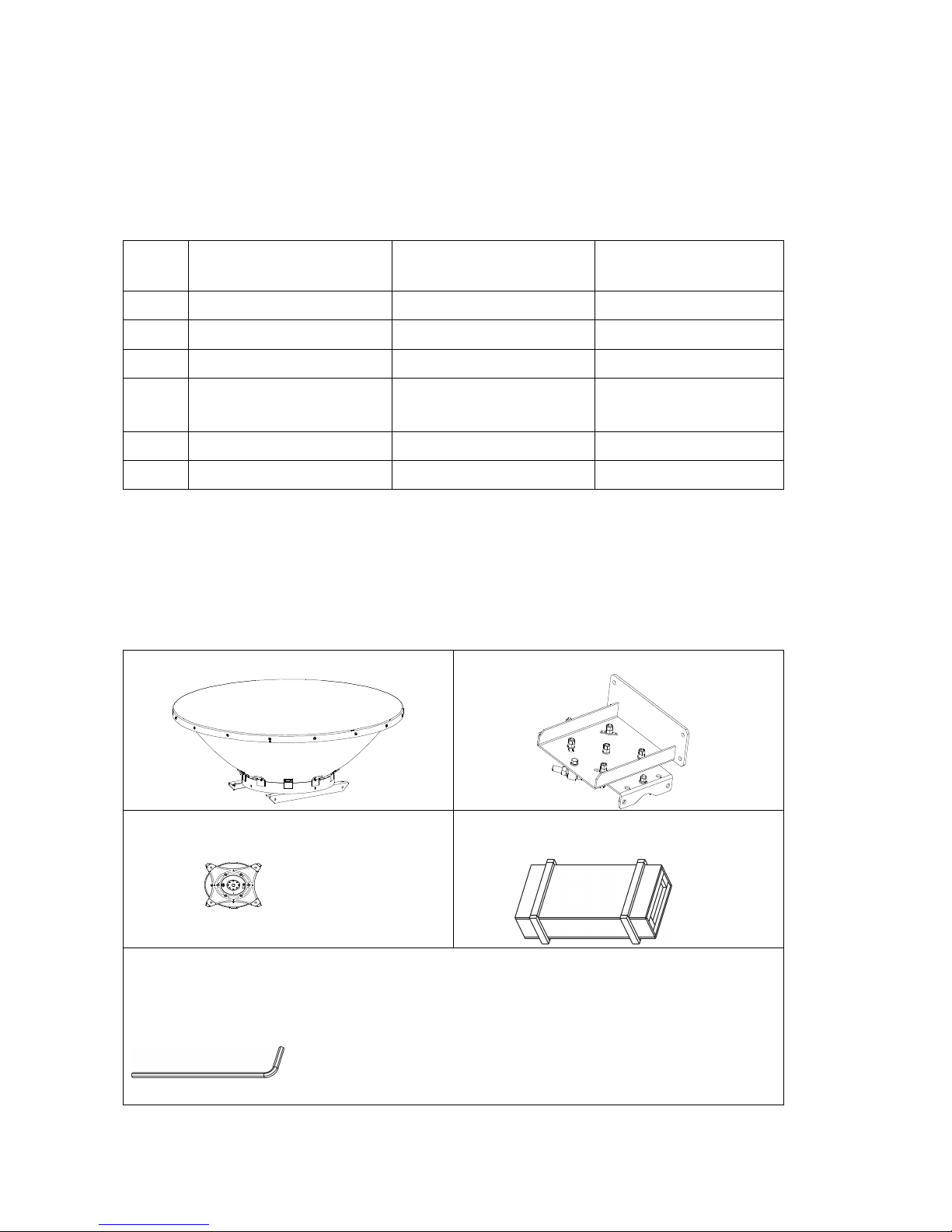
Open the shipping box, check the components according to the following list.
Table 2 - Packing list
1.Main dish (1 set)
2.U-plate assembly (1 set)
3.Side Strut Assembly (1 set)
4 .Accessories Box (1 set)
(Check the List in Table 3)
Data bag
Packing list (1 pcs) Specification of Antenna (1 pcs) Mounting instruction (1 pcs)
Allen Key S=3 (1 pcs)
- 6 -
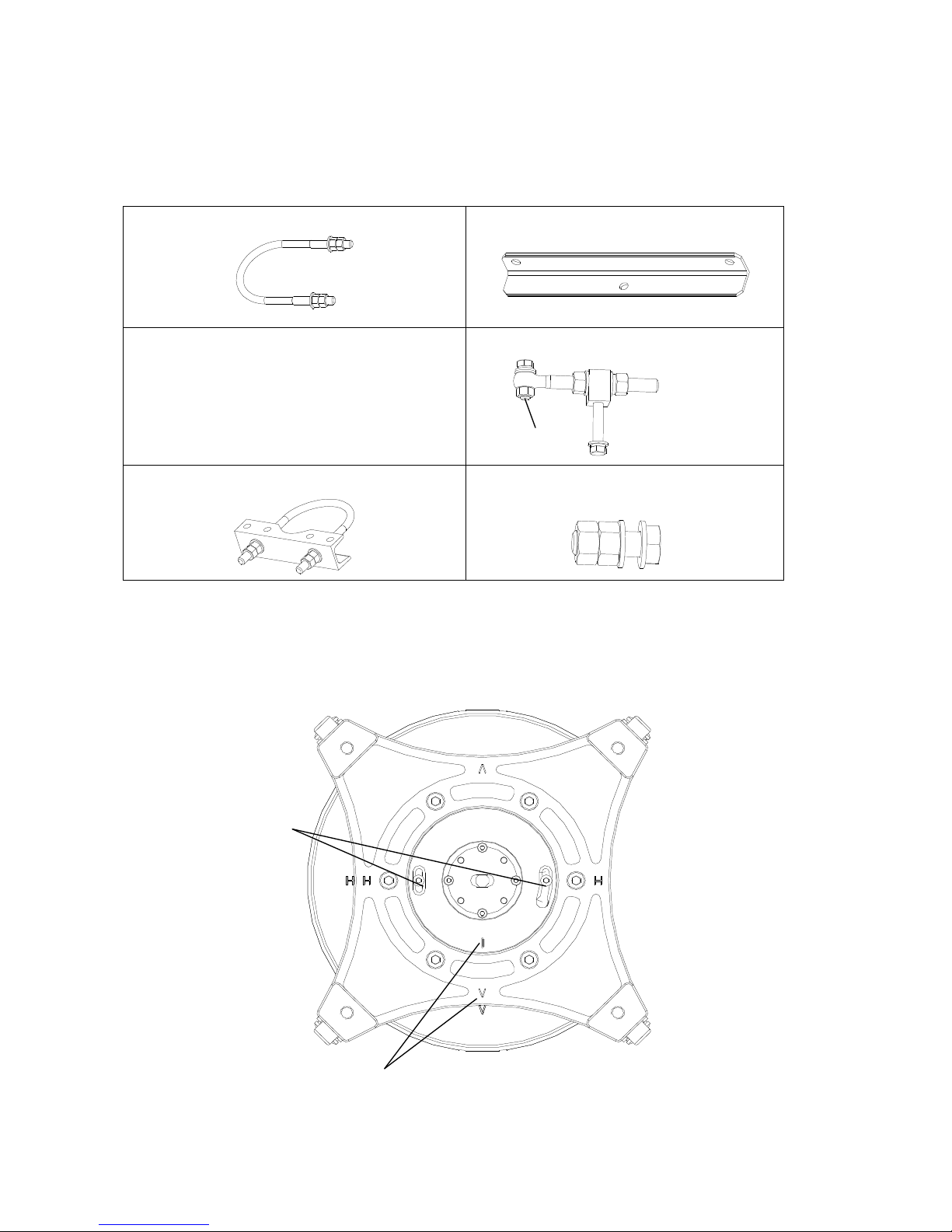
Please kindly check all the parts in Accessories Box according to Table 3 below
Table 3 - Accessories Box according List
1. U-Bolt ( with 4 nuts and 2 flat washers) (2 sets)
2. Short Corner Connector (1 pcs)
3.Anti-slide corner bracket component(1 set)
4. Articulated bolt assembly(1 set)
5. Anti-slide corner bracket(1 set)
6.Bolt M12*40, Double flat washers, Double
nuts (4 sets)
2.2
Mounting steps
2.2.1 Transfer Polarization
Check and confirm the required polarization before mounting. The detail is shown in figure 3.
Remove two screws, transfer
the polarization and then load
and fasten them
Align the polarization
mark (in red) to "V" mark
Spare nut

- 7 -
a. Vertical Polarization
b. Horizontal Polarization
Figure 3 - Polarization
2.2.2 Install panning system to the antenna
First use a bolt M12*40, two flat washers and two nuts (2 sets) to install Short Corner Connector to the
Long Corner Connector, second use a bolt M12*40, two flat washers, two nuts (2 sets) and a bolt
M12*50, two flat washers, two nuts (2 sets) to install U-plate assembly to the Long Corner Connector as
shown in figure 4.
Align the polarization
mark (in red) to "H"
Remove two screws,
transfer the
polarization
and then load and fasten

- 8 -
Figure 4 - Install panning system to the antenna
2.2.3 Install Anti-slide corner bracket
First roughly decide the direction of the antenna. Install the corner bracket onto the proper height of the
mounting pole. The channel steel direction should be 45°between the antenna directions as shown in
figure 5. Fasten all the nuts in the end.
Figure 5 - Install Anti-slip corner bracket
Long Corner Connector
M12*
50
Bolt
M12*40 Bolt
Short
Corner Connector
M14 nuts (4 pcs),
Flat washers (2 pcs)
Need to fasten Antenna direction
Channel steel
direction

- 9 -
2.2.4 Lift the antenna to a tower
Lift the antenna to a tower with a rope through the lifting hole as shown in figure 6. In order to avoid the
antenna rotation, you need to tow the antenna with another rope as shown in figure 6.
`
Figure 6 - Lift the antenna
Attention: To avoid falling and damage, please make sure the rope is tighten before lifting. During
the installation, please protect the antenna from hitting of other objects due to the wave of the antenna
resulting from the wind or other causes.
2.2.5 Install the antenna to the mounting pole
Lift the antenna on the anti-slip corner bracket of the mounting pole. Diameter ranges of pole for this
Mounting Bracket: Φ115 mm. Install the antenna to the mounting pole with 2 U-bolts, 8 nuts (M14), 4 Flat
washers. Mounting assembly must be clung to the anti-slip corner bracket. Moreover, the channel steel
direction should be 45°between the antenna directions as shown in figure 7. Don’t fasten all the nuts
now.
Rope
Lifting hole
Rope towing antenna

- 10 -
Figure 7 - Install antenna to the mounting pole
2.2.6 Install articulated bolt assembly
Install articulated bolt assembly onto the anti-slip corner bracket and mounting bracket assembly as
shown in figure 8.
Figure 8 - Install articulated bolt
U-bolt (2 pcs)
Nuts (8 pcs) Flat washers (4 pcs
)
Bolt M12*70
,
split washer
,
Flat washer
Articulated bolt

- 11 -
3 Antenna adjustment
3.1
Azimuth adjustment
Loose the double nuts as shown in the figure 9-10 below to adjust antenna azimuth. The azimuth range
is ±15°.
Figure 9 - Adjust antenna azimuth 1
Figure 10 - Adjust antenna azimuth 2
Loose the double nuts(M16)
here to
adjust the antenna azimuth
- 12 -
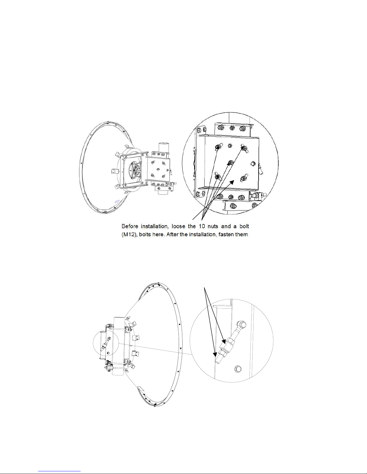
3.2
Elevation adjustment
Loose the nuts, bolts as shown in the figure below. After the installation, fasten them. Then loose the
nuts as shown in figure 11 to adjust antenna elevation. The range is ±10°, as shown in figure 11-13.
Adjust azimuth and elevation repeatedly until get the antenna to the proper position. Fasten mounting
assembly, U-bolt, bolts of corner bracket assembly, articulated bolt assembly and all the other bolts and
nuts.
Figure 11 -Adjust antenna elevation 1
Figure 12 - Adjust antenna elevation 2
Loose
the double nuts here to adjust antenna
elevation.After adjusting, fasten them.

- 13 -
Figure 13 - Adjust antenna elevation 3
3.3
Install side strut assembly
Install side strut assembly on the mounting pole and side strut tower end clamp as shown in figure 14.
Don’t fasten the bolts and nuts.
Figure 14 - Adjust antenna azimuth
Bolt M12*45, flat washers, nuts

- 14 -
3.4
Install Anti-slide corner bracket component adjustment
Diameter ranges of pole for this Anti-slide corner bracket component: Φ50÷Φ110 mm. (see figure 15)
Figure 15 - Side strut assembly mounting 1
Attention: Installing the side strut, the angle limit is 25°in horizontal and vertical direction
as shown in figure 16. If the angel is over the limit, please change the position of the side strut
tower end clamp on the tower.
Figure 16 - Side strut assembly mounting 2
- 15 -
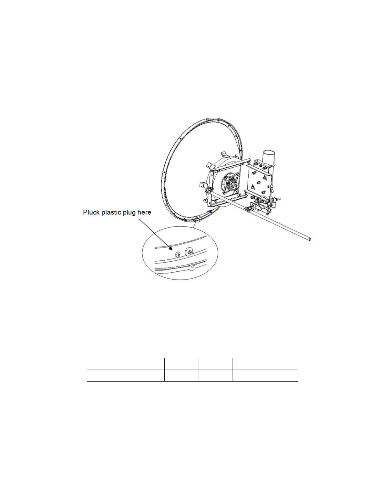
4 Pluck the plastic plug
Make sure every parts are installed correctly, then pluck plastic plug of plug hole at the very bottom of
the antenna as shown in figure 17.
Figure 17 - Pluck the plastic plug
Attachment: Mechanical Torque
Diameter of screw (mm) 8 12 14 16
Moment (N·m) 11.3 38.2 62.5 93.1
5 Final check
When the installation of the antenna has been completed, it is necessary to make sure that the
installation instructions has been followed in all aspects. It is especially important to check that all bolted
joints are tightly locked.
This manual suits for next models
4
Table of contents
Other BrasilSat Antenna manuals


Popular Antenna manuals by other brands


Ubiquiti
Ubiquiti PowerBeam M PBE-M2-400 quick start guide

Hirschmann
Hirschmann RAD 015-108 RD/S Mounting instructions

Diamond
Diamond MAY1000 Operation instructions

Electrovision
Electrovision T143EB quick start guide

Novatel
Novatel GPS-302L-A40 user guide

TraffiCalm
TraffiCalm M75-SPTOP-000S Important information