Brass Flame PF70 User manual

INSTALLATION
AND OPERATION MANUAL
Freestanding and Insert
Models~
PF70 series
PUBLICATION # 7186
Pellet Fired Appliance
This appliance must be installed by a qualified
technician. Read this manual thoroughly before,/
/
installation. Save this manual for future
refe~ence.
/
REV#
8/95


IMPORTANT: Read thoroughly before starting installation. Failure to
follow these installation instructions may result
In
a possible fire hazard and
will void the warranty. Save this manual for future reference.
Table
of
Contents
Safety Notice
-------------------------------------~-------------
1
Introduction
----------------------------------------------------
2-3
Component Overview
------------------------------~------
2
I-Iow
it Works
---------------------------------------------3
Installation
-----------------------------------------------------
5 -
15
Selecting a Location
--------------------------------------5
Assembly: legs/pedestal/ash lip/handle
--------------------5
Pre-installation Procedure
---------------------------------6
Paint Cure-In Period
--------------------------------------6
Clearances
------------------------------------------------7
Venting Requirements
------------------------------------9
Horizontal Exhaust Through
Wall
-------------------------11
Direct Vent
-----------------------------------------------
I1
Outside Vertical Through the Roof Installation
------------
12
Inside Vertical Through the RoofInstallation
--------------13
Installation into masonry & factory built fireplaces
--------14
Mobile Home Installation
---------------------------------15
Outside Air Provision
-------------------------------------15
Operation
------------------------------------------------------
16
Control Panel Functions
----------------------------------
16
Maintenance
---------------------------------------------------
17-19
Routine Inspection Requirements
-------------------------
17
Cleaning Procedure
---------------------------------------18
Maintenance Related Problems/Solutions
-----------------
19
Troubleshooting
------------------------------------------------20-21
Specifications
--------------------------------------------------22
Glossary
of
Terms
----------------------------------------------23
Component Diagram
-----------,--------------------------------24
Power Flow Diagram
-------------------------------------------25
Wiring Schematic
----------------------------------------------
26
Warranty
-------------------------------------------------------
27

IMPORTANTSAFETY NOTICE
PLEASEREAD BEFORE ATTEMPTING
TO
BURN!
CAUTION:
lftltis
stove
is
llOt
properly
installed,
alwusefire
may
result.
Foryoursq{e{r,follow tlte
installation
directiolls;
contactlocal buildingofficials
about
restrictions
am/
installation
inspection requirements
in
your
area.
I.
Installation
of
tilis
stove
must
comply
with
local
codes.
A
building
or
installation
pemlit
may
be
required.
Check
witi1
your
local
building
official
or
fire
department
before
installing.
2.
If
utilizing
an
existing
chimney,
have
your
fireplace
flue
or
chimney
system
inspected
by
a
qualified
person
prior
to
installation
of
ti1e
stove.
Make
any
necessary
repairs
before
installing.
3.
Never
connect
stove
flue
to
chimney
being
presently
used
by
another
appliance.
4.
Never
block
any
air
intake
or
air
outlet
ports.
Dangerous
overheating
can
result.
5.
Do
not
install
tilis
stove
in
a
sleeping
room.
G.
Never
connect
the
stove
to
an
air
duct
system.
7.
Never
stack
or
pile
combustible
materials
against
the
stove
or
around
external
vent
tennination.
8.
To
avoid
bums,
children
and
adults
should
be
alerted
to
the
hazards
of
high
surface
temperatures.
9.
To
provide
reasonable
fire
safety,
install
a
smoke
detector
and
a
converliently
located
fire
extinguisher.
10.
In
the
event
of
a
chimney
fire,
notifY
ti1e
fire
department
and
unplug
the
stove.
11.
Tenninate pellet vent
pipe
so
timt
contact
with
humans
orpossible
damage
to
pipe
is
avoided.
12.
The
exhaust
vent should
be
inspected
at
least
once
a
month
and
cleaned
at least
annually.
13.
If
you
overfue
the
unit,
(constant hlgh
heat)
you
will
shorten
the
life
of
the
electrical
components.
14.
When
installed
into
a
mobile
home,
it
must
be
electrically
grotmded
to
the
steel
chassis
of
ti1e
home
and
bolted
to
the
floor.
15.
Do
not
bum
with insufficient combustion
air.
Be
sure
to
maintain
the
structural
integrity
of
ti1e
home
when
passing
a vent
ti1ough
walls,
ceilings
or
roofs.
A
periodic
check
is
recommended
to
assure
proper
combustion
air
is
admitted
to
the
combustion
chan1ber.
16.
Since
the
stove's
exhaust
system
works
'-Vitl1
negative
combustion
chamber
pressme
and
a
slightly
positive
chimney
pressme,
it
is
very
important
to
assure
timt
the
exhaust
system
be
sealed
and
airtight
when
connecting
different
chimney
lengti1s.
Make
sure
ti1at
the
connections
are
well
sealed.
17.
·n1is
appliru1ce
has
been
designed
to
bum
pelletized
wood
fuel
only.
Do
not
attempt
to
bLU11
cordv,:ood
or.
pressed
logs
in
the
stove,
severe
dmnage
or
fire
could
result.
Buming
improper
fuel
\\·ill
void
wmmnty.
18.
Since
there
arc
lll<my
numul~1cturcrs
of
wood
pellets,
it
is
importmlt
to
select
pellets
that
me
fi·ee
of
dirt
or
any
impmities.
·n1e
Association
Of
Pellet
Fuel
Industries
(A.P.F.I.)
has
established
a
standard
for
pellet
manufactming.
We
recommend
that
you
purchac;e
pellets
that
meet
tl1ese
standmds.
Ask
your
local
dealer
for
a
recommended
pellet-type.
Fines
Bulk
Density
Size
Ash
Content
I%
max
..
through
a
1/8"
screen.
40
lbs.
per
cu.
ft.
min.
1/4"
to
3/8"
dia.,
1.5"
longmax.
1%
max.
Moisture Content 8%
max.
Heat
Content Approx.
8200
BTU
per
lb.
min.
Testing/Listing
The
PF70
pellet
ftred
wood
heater
confonns
with
ti1e
safety
standru·d
UL1482,
for
residential
room
heaters
witl1
vertical
or
horizontal
connector
in
ti1e
freestanding
straight
or
comer
modes
and
for
use
in
mrumfactured
dwellings
ru1d
park
trailers
according
to
OAR
918-520-010
through
918-520-110.
ll1e
PF70
also
confonns
to
UL907
and
UL127
pertaining
to
use
as
ru1
insert
into
a
masonry
fireplace
or
ru1
approved
factory-built
zero
clearance
fireplace
with
direct
cmmect
only.
Outside
combustion
air
is
required
for
all
mrumfactured
home
installations
and
is
optional
in
all
otl1er
installations.
Listing
Laboratmy
(safety):
EESPC;
Kent,
WA
98032.
Listing
file
#92-040.
Based
on
a
tested
air
to
fi.Jel
ratio
in
excess
of 3
5:
1,
tllis
appliance
is
not
ru1
effected
facility
w1der
the
EPA
regulations
for
wood
bLU11ing
stoves.
Listing
Laboratory
(enlissions):
EEMC,
Kent;
WA
98032
Page
I
INTRODUCTION Read Entire Manual Before Atten1pting to
Burn
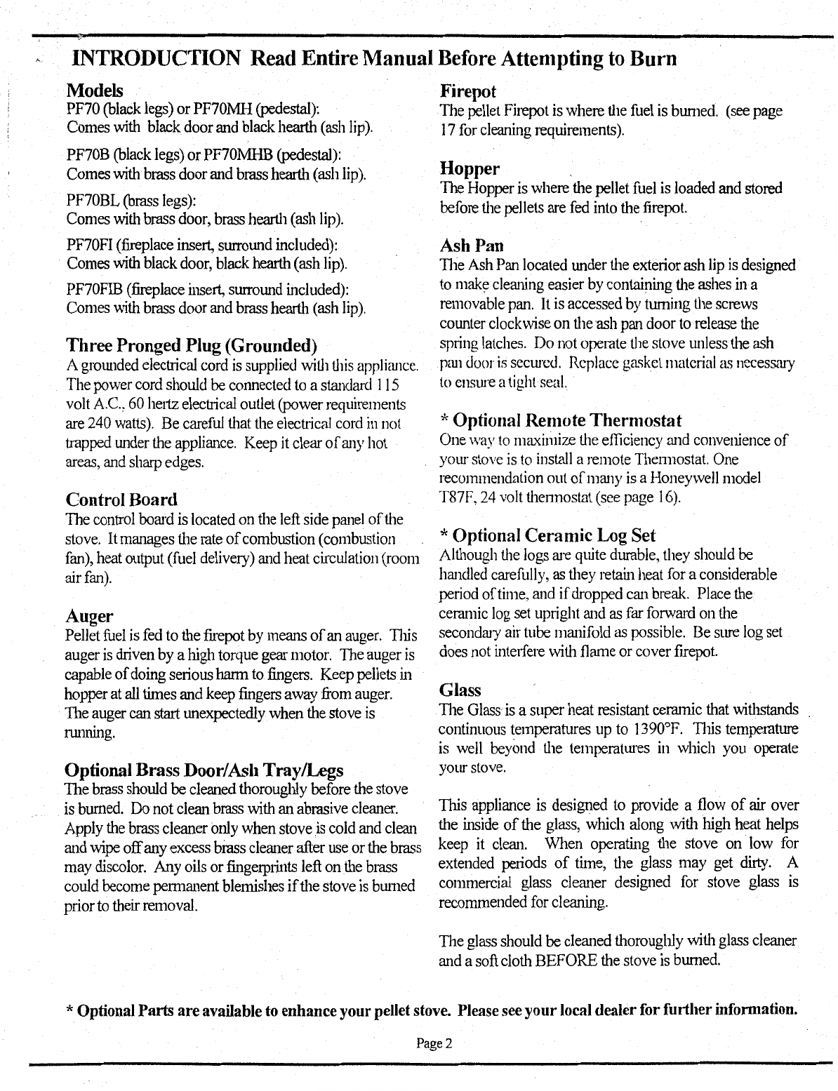
Models
PF70
(black
legs)
or PF70MH
(pedestal):
Comes
with
black door
and
black
hearth
(ash
lip).
PF70B
(black
legs)
or PF70MHB
(pedestal):
Comes
with
brass door
and
brass hearth
(ash
lip).
PF70BL
(brass
legs):
Comes
with
brass
door,
brass
hearth
(ash
lip).
PF70FI
(fireplace
insert,
surroWld
included):
Comes
with
black
door,
black
hearth (ash
lip).
PF70FIB
(fireplace
insert,
surroWld
included):
Comes
\vith
brass
door
and
brass
hearth
(ash
lip).
ThreePronged Plug (Grounded)
A
grmmded
electrical
cord
is
supplied
with
this
applicmcc.
The
power
cord
should
be
connected
to
a
standard
I
15
volt
A.
C.,
60
heriz
electrical
outlet
(power
requirements
are
240
watts).
Be
careful
that
the
electiical
cord
in
not
trapped
under
the
appliance.
Keep
it
clear
of
any
hot
areas,
and
sharp
edges.
Control Board
The
control
board
is
located
on
the
left
side
panel
of
the
stove.
It
manages
tl1e
rate
of
combustion (combustion
fan),
heat
output
(fuel
delivery)
and
heat
circulation
(room
air
fan).
Auger
Pellet
fuel
is
fed
to
fue
frrepot
by
means
of
an
auger.
11us
auger
is
chiven
by
a
high
torque gear
motor.
The
auger
is
capable
of
doing
seiious
harm
to
fingers.
Keep
pellets
in
hopper
at
all
tinles
and
keep
fingers
away
from
auger.
The
auger
can
start
unexpectedly when the stove
is
nummg.
Optional BrassDoor/Ash Tray/Legs
The
brass
should be cleaned thoroughly
before
fue
stove
is
burned.
Do
not clean brass with an abrasive
cleaner.
Apply
the
brass
cleaner
only
when stoveis
cold
and
clean
and
wipe
offany
excess
brass cleaner after
use
or
the
brass
may
discolor.
Any
oils
or
fingerprints
left
on
the
brass
could
become
permanent blemishes
if
the stove
is
brnned
prior
to
their
removal.
Firepot
The
pellet
Firepot
is
where
the
fuel
is
bW11ed.
(see
page
17
for
cleaning
requiremenL<;).
Hopper .
The
Hopper
is
where the pellet
fuel
is
loaded
and
stored
before
the
pellets
are
fed
into
fue
firepot.
Ash Pan
1l1e
Ash
Pan
located
Wlder
tl1e
exteiior
ash
lip
is
designed
to
mak~
cleatling
easier
by
containing
the
ashes
in
a
removable
pan.
It
is
accessed
by
turning
the
screws
coWlter
clockwise
on
tl1e
ash
pan
door
to
release
the
spring
latches.
Do
not
operate
the
stove
unless
the
ash
pm1
door
is
sccw·cd.
Replace
ga<>kct
material
as
necessary
to
ensure
a
tight
seal.
*Optional Remote Thermostat
One
\Vay
to
ma'{imize
the
efficiency
and
converuence
of
yom
stove
is
to
install
a remote Thennostat.
One
recommendation
out
of
mat1y
is
aHoneywell
model
T87F,
24
volt
thennostat
(see
page
16).
*Optional Ceramic Log Set
Although
the
logs
me
quite
durable,
they
should
be
hat1dled
carefully,
as
tl1ey
retain
heat
for
a considerable
period of
time,
at1d
ifdropped
c.:111
break.
Place
the
ceratnic
log
set
uptight
atld
as
far
forwat-d
on
the
secondaty
air
tube
mat1ifold
as
possible.
Be
sure
log
set
does
not
interfere
with
flatne
or cover
firepot.
Glass
1l1e
Glass
is
a super heat resistant ceramic
that
withstands
continuous temperatures
up
to
1390°F.
111is
temperature
is
well
beyond
tl1e
temperatmes
in
which
you
operate
your
stove.
This
appliance
is
designed
to
provide a
flow
of
air
over
the
inside
of
the
glass,
which along with high heat
helps
keep
it
clean.
When operating the stove
on
low
for
extended
peliods
of
time, the glass may
get
dirty.
A
commercial
glass
cleat1er
designed
for
stove
glass
is
recommended
for
cleaning.
1l1e
glass
should
be
cleat1ed
fuoroughly
witl1
glass
cleat1er
and
a
soft
cloth BEFORE the stove
is
burned.
*OptionalParts
are
available to enhanceyourpellet stove. Please see
your
local dealer for further infonuation.
Page2
INTRODUCTION (Continued)
HOW IT WORKS
The Control Board manages the rate
of
combustion
(<.Iran
fan), fuel delivery/heat output (auger gear
motor), and heat circulation (room air fan).
Draft Fan Operation )
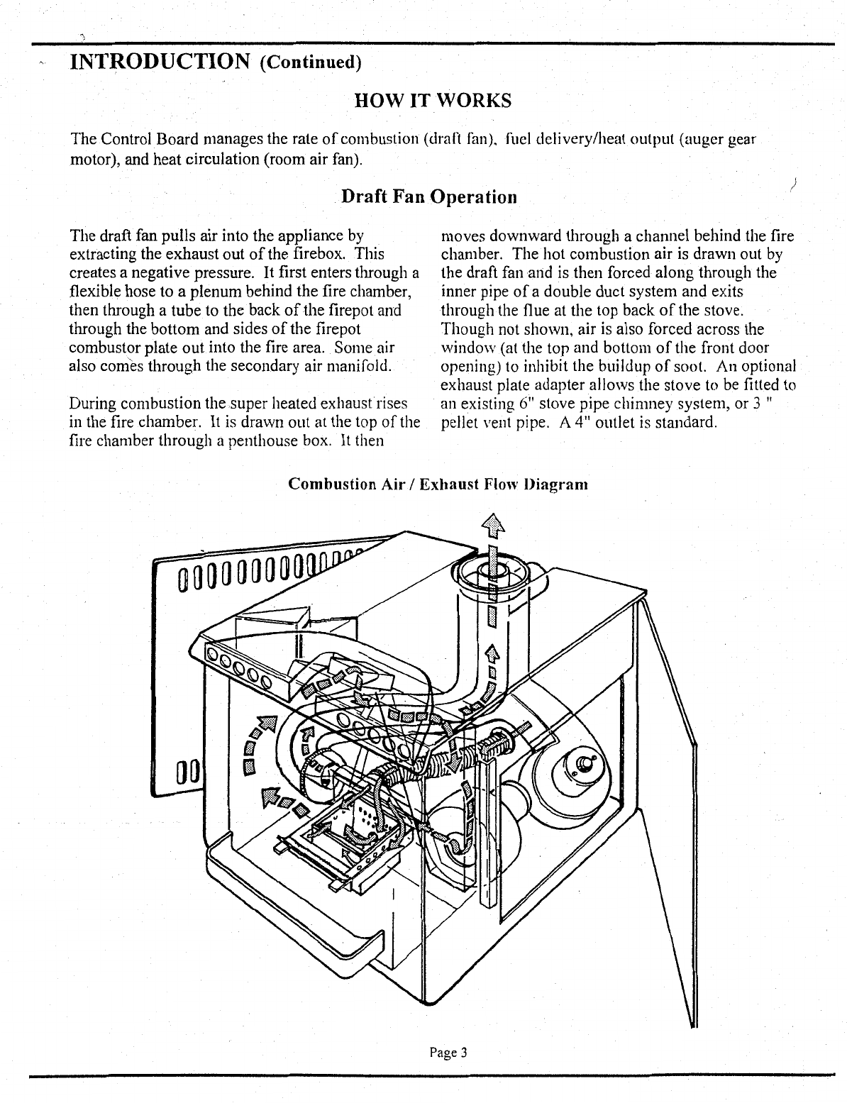
The draft fan pulls air into the appliance by
extracting the exhaust out
of
the firebox. This
creates a negative pressure.
It
first enters through a
flexible hose to a plenum behind the fire chamber,
then through a tube to the back
of
the firepot and
through the bottom and sides
of
the firepot
combustor plate out into the fire area. Some air
also comes through the secondary air manifold.
During combustion the.super heated exhaust
rises
in the fire chamber.
It
is drawn out at the top
of
the
fire chamber through a penthouse box.
It
then
moves downward through a channel behind the fire
chamber. The hot combustion air is drawn out by
the draft fan
and
is then forced along through the
inner pipe
of
a double duct system and exits
through the flue at the top back
of
the stove.
Though not shown, air is also forced across the
window (at the top and bottom
of
the front door
opening) to inhibit the buildup
of
soot. An optional
exhaust plate adapter allows the stove to be fitted
to
an existing
6"
stove pipe chimney system, or 3 "
pellet vent pipe. A 4" outlet
is
standard.
Combustion
Air
I
Exhaust
Flol\'
Diagram
ooooooooo
Page 3

INTRODUCTION (Continued)
Aug~.r
G~ar
Motor
The Auger Gear Motor drives the auger
to
deliver pellets to the firepot according to the feed rate
determined by the fuel rate switch setting.
Auger
~JJ..JIIt-"----~
Auger
Gear
Motor
Room
Air
Fan
Operation
Room air is drawn through the slot openings
in
each side panel by the room air fan and is forced through
the outer pipe
of
the double duct system. The room air is pushed upwards at the back
of
the fire chamber
through it's own manifold
to
the top
of
the stove. The air passes around the super heated penthouse box,
picking up more heat as it flows. Then the air is forced out
of
the front
of
the stove through I0 holes.
Room
Air
Fan
Flow Diagram
Page4
INSTALLATION
Selecting a Location
The
design
of
your
home
and
where
you
place
ymrr
stove
will
determine
its
value
as
a
source
of
heat.
Practical
considerations
may
be
most important
in
selecting
a
location:
Existing
Chimneys
Room
Traffic
Proximity
to
combustibles
Aesthetic
Considerations
Electrical
Wiring
RoofDesign
(rafter
locations
& roof
pitch)
Do
not
install
stove
in
abedroom
Once
your
options
are
determined,
consult
with
your
local
building
official
regarding
any
potential
problems.
If
you
plan
to
vent your
stove
into
any
existing
masonry
chimney,
have
it inspect
by
a
local
fire
marshal
or
qualified
installer.
A
stoves
performance
is
heavily
influenced
by
the
chimney.
Suggestions:
Locate
this
appliance
in
a
large
and
open
room
centrally
located
in
the
dwelling
to
optimize
heat
circulation.
For
optimwn
perfom1a..nce
the
manufacturer
recommends
a Top
Vent
installation
with pellet
vent
chimney
pipe
rw1
up
through
the
eave
as
opposed
to
a
Direct
Vent
installation.
A
Direct
Vent
installation
is
where
the
vent
tenninates
on
an
outside
wall
directly
behind
the
stove
with
no
vertical
pipe.
In
the
event
ofa
loss
of
power,
when
installed
as
aDirect
Vent,
natural
draft
is
not
present
and
may
allow
smoke
back
into
the
dwelling.
Assembly
TI1e
Model
PF-70 comes with apedestal,
or
four
legs
or
can
be
iristalled
as
an
insert.
To
assemble
leg
or
pedestal
based
units:
1.
Remove
metal
pedestal
(or
legs)
from
the
box.
2.
Remove
the
box
from
the
appliance.
3.
Place
the
appliance
on
top
of
the
pedestal
(or
support
the
stove
while
you
attach
each
leg).
4.
Secure
the
stove
and
pedestal (or legs)
by
fastening
them
to
the
bottom
of
the
stove
using
the
screws
supplied
(4)
5/16-18x3/4"
for
pedestal, or
(4)
1/2-13x
1
1/4"
for
legs.
Remove
ash
lip
from
box.
Install
below
door
opening
to
the
two
(2)
corresponding
threaded
holes
in
the
stove
front,
using
the
two
(2)
5/16-18
x
3/4"
socket
(allen)
head
screws
provided.
This will
require
the
use
of
a
size
1/4"
Allen
wrench
tool, not
provided.
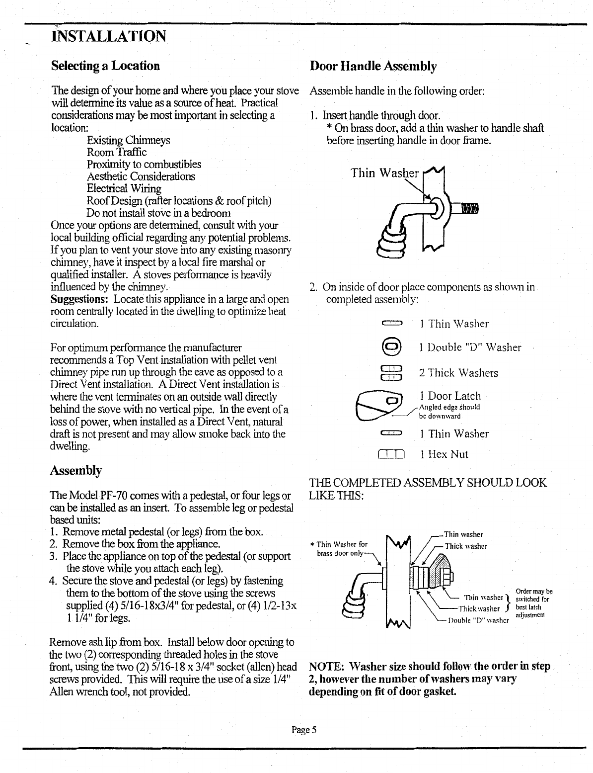
DoorHandle Assembly
Assemble
handle
in
the
following
order:
1.
Insert
handle
through
door.
*
On
brass
door,
add
a
thin
washer
to
handle
shaft
before
inserting handle
in
door
frame.
2.
On
inside
of
door
place
components
as
sh0\\11
in
completed
assembly:
an
an
I Thin Washer
1Double
"D"
Washer
2 Thick Washers
c:r::o I Thin Washer
IT.D 1 Hex Nut
THE
COMPLETED ASSEMBLY SHOULD
LOOK
LIKE
THIS:
*
Thin
Washer
for
NOTE: Washersize should
follo·w
the
order
instep
2,
however the
number
of
washers may vary
depending on fit
of
doorgasket.
Page5
,'
INSTALLATION
Pre-Installation Procedure
Note: Before
unit
is installed
it
is recommended
that it be pre-burned to verify the operation. This
will also allow
it
to
bum
off
sub-surface oils that
may be present, and
to
help cure the paint. The
"Pre-Installation Procedure" should be done in a
well ventilated
ar~a
as follows:
I.
Plug the stove into a grounded outlet (using a
circuit tester, verify the electrical outlet for
proper ground and polarity
where
the unit will
be installed. failure to do so could result in
damage to the electrical components and void
the warranty).
2.
Switch on
power
by pressing OFF/ON switch
(lower rocker switch) upward to the
"ON"
position.
The
LED (light emitting Diode) light
will come
on
and
glow
red (early production
models
glow
green). The Draft
Fan
will come
on.
3.
Look
down
into the
Hopper
and
make
sure
nothing is obstructing the auger. Pour
114
bag
of
pellets in
the
Hopper.
4. Set Feed
Rate
Control Switch to
low
or
medium-low setting.
5. Press auger Jog/Start switch (upper rocker
switch)
downward
to initiate 12 minute start
cycle. The
LED
lamp
will
now
appear orange
during this 12 minute period. This will bypass
the
low
temperature limit disc (snap switch) and
allow the
auger
to feed pellets to firepot at the
feed rate setting selected.
6.
Apply
nonvolatile lighting material to the pellets
and light
it
with
a match.
Let
the
fuel burn for
five minutes leaving the
door
slightly ajar.
7.
If
the stove
has
not
warmed
sufficiently after the
12 minutes
(LED
will revert
back
to red
glow-
earlier
models
glow
green) to keep auger
dropping pellets
(low
limit thermostat will not
have reached set temperature to close contacts
and complete the auger circuit), merely repress
rocker
switch
to
restart 12
minute
cycle.
During this
time
the
feed rate
should
become
automatic.
8.
Pressing Auger/Initiate switch upward will
manually engage auger.
This
can occur only
after start cycle is started
or
stove is at operating
temperature.
This
would be used to more
quickly get the
auger
to start pellets dropping
when hopper is refilled after running out
of
pellets.
8.
Set Fuel rate
switch
to desired
heat
output by
turning the
knob
clockwise. This will increase
the burn rate from low to
medium-low
to
medium-high to high.
9. Once ru1ming, observe the stove operating for
15-30
minutes.
1
0.
J\s
the stove temperature rises, the Room J\ir
Fan
will automatically be engaged.
11.
Once the stove is operating properly, complete
filling the
Hopper
and run the unit for 30
minutes.
Paint
Cure-In
Period
Your stove finish is a high temperature paint that
requires time and temperature for the silicon resin
in the paint to completely cure. Depending on your
use, this may take a few hours
or
a few days. The
paint manufacturer
recommends
you ventilate the
house during the initial burns.
Although
the
emission is primarily Carbon Dioxide, there are
other components emitted
which
make
it smell bad
and may irritate
some
people.
Do
not
place
anything on the
stove
surface until
the
paint is
completely cured, as it will
become
soft during this
process.
Do
not
attempt
to repaint the stove until
the paint is completely cured.
If
the surface later
becomes stained
or
marred, it
may
be
lightly
sanded and touched
up
with spray
paint
from the
same paint manufacturer:
Paint
is available at your
local dealer.
KEEP YOUR HOUSE
WELL
VENTILATED.
DURING
THE
CURING PROCESS.
THE
CHEMICAL
SMELL
AND BLUISH HAZE
EMITTED
BY
THE
CUIUNG PAINT CAN BE
QUITE
NOTICEABLE AND MAY SET OFF A
SMOKE DETECTOR.
Page 6

·~··
CLEARANCES
Standard
Residential
or
Mobile Home Installation
FREESTANDING MODELS: PF70;
PF70MH, PF70B, PF70MHB; PF70BL
Minimum Clearances to Combustibles
Side: 3"/75mm
Back: 2"/50mm
Comer 2"/50mm horizontal from door
Alcove Installation *
This appliance may be installed in an alcove which
meets the following requirements:
Alcove height: 60"/1500
mm
minimum
Alcove width: 30"/750
mm
minimum
Alcove depth: 36"/900mm maximum
Corner
Installation
The pellet exhaust vent shown in the installation
to
the
nght
can penetrate either side wall or use an
inside vertical installation.
Pipe Requirements/Clearances
The required type
of
pipe is Ryder or
Dura-
Vent
(brand) listed pellet vent pipe. Additional
Approval: Minimum 24 gauge single wall pipe
may be used in mobile home and residential
freestanding configurations.
Approved Sizes: 3"/75mm
4"/lOOmm
6"/150mm
Maximum total horizontal run: 36"/9I5mm
Offsets allowed: 2 maximim (not to exceed total
of
180° in direction change).
Pellet vent pipe requires 3"/75mm clearance from
outside
of
pipe (all diameters: 3", 4", 6").
Floor Protection
Non-combustible floor protection must fully cover
the area beneath the appliance and extend
4"/lOOmm in front
of
the door opening and
2"/50mm beyond sides and back
of
appliance.
s
d
e
w
a
Back
wall
3"
M------i-+1
Floor Protection
4"
in
front
of
door
opening.
2" beyond sides and back.
Wall Thimble
I'v1anufactured
by
Pellet Vent
Manufacturer
Horizontal Exhaust
Through The Wall
Floor Protection
*IF
INSTALLED
TO
THE
MINIMUM SIDE
AND
REAR CLEARANCES IN
AN
ALCOVE,
REMOVAL
OF
THE
APPLIANCE MAY BE
NECESSARY
FOR
SERVICING.
Page 7
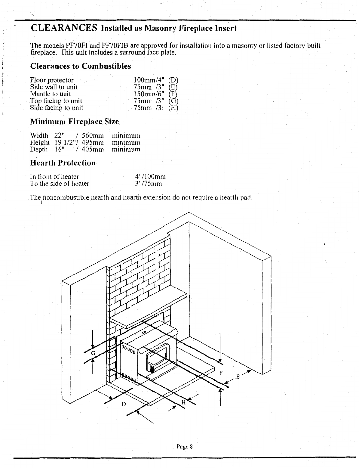
CLEARANCES Installed as Masonry Fireplace Insert
The
models PF70FI and PF70FIB are approved for installation into a masonry or listed factory built
fireplace. This unit includes a surround face plate.
Clearances to Combustibles
Floor protector
Side wall to unit
Mantle to unit
Top facing to unit
Side facing to unit
Minimum Fireplace Size
100mml4" (D)
75mm
13"
(E)
150mml6" (F)
75mm
13"
(G)
75mm
13:
(H)
Width 22" I
560mm
mnumum
Height
19
112"1
495mm
minimum
Depth 16" I
405mm
nunnnum
Hearth Protection
In front
of
heater
To the side
of
heater 4"1100mm
3"/75mm
The noncombustible hearth and hearth extension do not require a hearth pad.
I .
Page 8
INSTALLATION
ALLCLEARANCESIINSTRUCfiONS LISTED
BY
PIPE
MANUFACI'URER MUST
BE
FOLLOWED.
VentingRequirements A
support
bracket
must
be
installed
every
5
feet
of
pellet
vent
pipe
on
the
exterior.
111is
appliance
is
sllipped
from
the
factory
with
a
standard
4"
flue
collar.
Optional
3"
and
6"
flue
collars
No
more
than
180°
of
elbows
allowed
(i.e.
two
90°
are
available
through
your
local
dealer.·
elbows
or
two
45°'s
and
one
90°,
etc.).
There
are
several
options
for
installing
and
venting
of
this
Maximum
rise
is
33'
if
vertical
only.
pellet
appliance.
Refer
to
clearances
before
installing.
The.most
desirable
installations
are:
Freestanding:
Pellet
vent
pipe
connected
to
top
of
the
stove
and
run
up
through
ceiling,
then
temlinating
above
the
roofline.
Place
the
appliance
a
working
distance
away
from
the
wall.
Insert:
Listed
PL
type
liner
fi"om
the
appliance
to
tennination.
Choose
the
appliance
location
with
the
least
runow1t
of
interference
with
the
house
frruning,
plumbing,
wiring,
etc.
Connect only one flue
per
appliance.
Maintain clearances in accordancewith NFPA 211.
The
required
type
of
pipe
is
Ryder
or
Dura-
Vent
(brand)
listed
pellet
vent
pipe
which
conforms
to
UL
stru1dard
641.
Additional
approval:
Minimum
24
gauge
single
wall
pipe
may
be
used
in
mobile
home
and
residential
freestru1ding
configurations.
WARNING:
DO
NOT
USE CLASS B VENTING
INTENDED
FOR
GAS APPLIANCES
AS
A
CHIMNEY
OR
CONNECTOR
PIPE
ON A
PELLET
FIRED
APPLIANCE.
Follow
pipe
manufacturers
installation
instructions
for
precautions
required
for
passing
vent
through
a
combustible
wall
or
ceiling
(i.e.
use
an
approved
thin1ble).
Maximwn
36"
total
horiwntallength
only.
You
may
connect
the
pellet
vent
pipe
to
the
flue
collar
using
three
screws
to
secure
it.
All
pipe
joints
and
collar
must
he
sealed
with
the
compmmd
supplied
vvith
the
pipe
or
a
RTV
silicone
with
a
rating
of
at
least
570°
F,
or
Interam
to
provide
a
complete
seal.
Page9
INSTALLATION
Vent
Termination
Requirements
Do not terminate vent in an enclosed or
semi-enclosed area such as: carports, garage, attic,
crawl space, under a sun deck, porch, narrow
walkway, closely fenced area, or any location that
can build up a concentration
of
fumes such as a
stairwell, covered breezeway, etc.
Vent surfaces can get hot enough to cause burns
if
touched by children. Non-combustible shielding or
guards may be required.
It
is recommended that when an appliance
is
vented
directly through
a wall, a minimum
of
five feet
of
vertical pipe should be installed to create some
natural draft. This will prevent the possibility
of
smoke or odor entering the dwelling during
appliance shutdown or loss
of
power and
to
keep
exhaust from causing a nuisance or hazard and
exposing people or shrubs to high temperatures. In
any case, the safest and preferred venting method
is
to extend the vent through the roof.
The termination
of
the outside chimney
of
the
pellet stove shall be located in accordance with the
following:
1.
Higher than 3 ft. above any forced air inlet (air
conditioner, etc.) located within I0 ft.
2.
Not
less that 4 ft. below, 4 ft. horizontally from
or 1 ft. above any gravity air inlet (door,
window, etc.).
3.
Not
less
that
2ft.
from combustible materials
such as
an
adjacent buildings, fences,
protruding parts
of
the structure,
roof
overhang,
plants and shrubs, etc. and not less than 7
ft.
above grade
when
located adjacent to the public
sidewalks (access).
4. Not less that 3
ft.
below an eave
or
any
construction that projects more that 2" from the
plane
ofthe
wall.
5.
Distance from bottom
of
termination and
grade-
12
inches minimum. This is conditional upon
· plants and nature
of
grade surface: The exhaust
gases are not hot enough
to
ignite grass, plants
and shrubs located in the vicinity
of
the
termination. The grade surface must not be a
lawn.
Connection
To
A Masonr·y
Chimney
Through
A Wall
Be sure
to
verify the construction
of
a masonry
chimney, as many have combustible framing.
The usc
of
single wall flex or rigid 24 gauge
galvanized or stainless steel pipe as a liner is
approved.
Connection
To
An Existing Class A
Chimney
A chimney adapter can be used to make the
cmmection from 3
",
4", or 6" pellet vent pipe
to
existing UL chimney system. Verify with the pipe
manufacturer that your pipe brands will
interconnect.
The
use
of
single wall flex or rigid 24
gauge galvanized or stainless steel pipe as a liner is
approved.
Page
10
INSTALLATION
Horizontal ExhaustThrough Wall
I.
Position
appliance
on
noncombustible
hearth
pad.
Locate
the
center
of
the
exhaust
pipe
on
the
appliance.
Extend
that
line
to
the
wall.
Once
you
have
located
that
center
point
on
the
wall,
use
a
saw
to
cut
a
7"/175mm
diameter
hole
(for
3"/75mm
vent),
8"/200mm
(for
4"/IOOmm
vent)
or
12"/300mm
(for
6"/150mm
vent).
Now
you
are
ready
to
install
the
wall
thimble
(PL
type).
Use
either
Ryder
or
Dura-
Vent
pellet
vent
pipe.
2.
(Optional)
Locate
and
cut
a
hole
for
combustion
air
pipe
using
step
one
procedure.
3.
Install
a
length
of
pipe
approximately
12"/300mm
into
the
wall
thimble
and
seal
pipe
joints.
4.
Push
the
lll1it
lll1til
the
pipe
connects
to
the
wall
thimble.
1l1e
pipe
should
pass
easily
through
the
wall
thimble.
5.
If
necessary,.
bring
another
pipe
length
(PL
type)
to
the
outside
of
the
home
and
connect
it
to
the
first
section.
1l1e
pipe
must
extend
at
least
12"/JOOmm
away
from
the
building.
6.
Install
vertical
pipe
or
if
all
requirements
for
direct
venting
are
met,
install
vent
termination.
1l1e
stainless
steel
cap
tennination
supplied
by
the
Pellet-Vent
manufacturer
is
recommended.
However,
if
the
vent
tenninates
several
feet
above
Non-Combustible
Hearth.Pad Cmnbustible
grow1d
level
and
there
are
no
trees,
plants,
etc.
within
several
feet,
a
45°
elbow
can
be
used
as
a
tennination.
the
elbow
must
be
tW11ed
down
to
prevent
rain
from
entering.
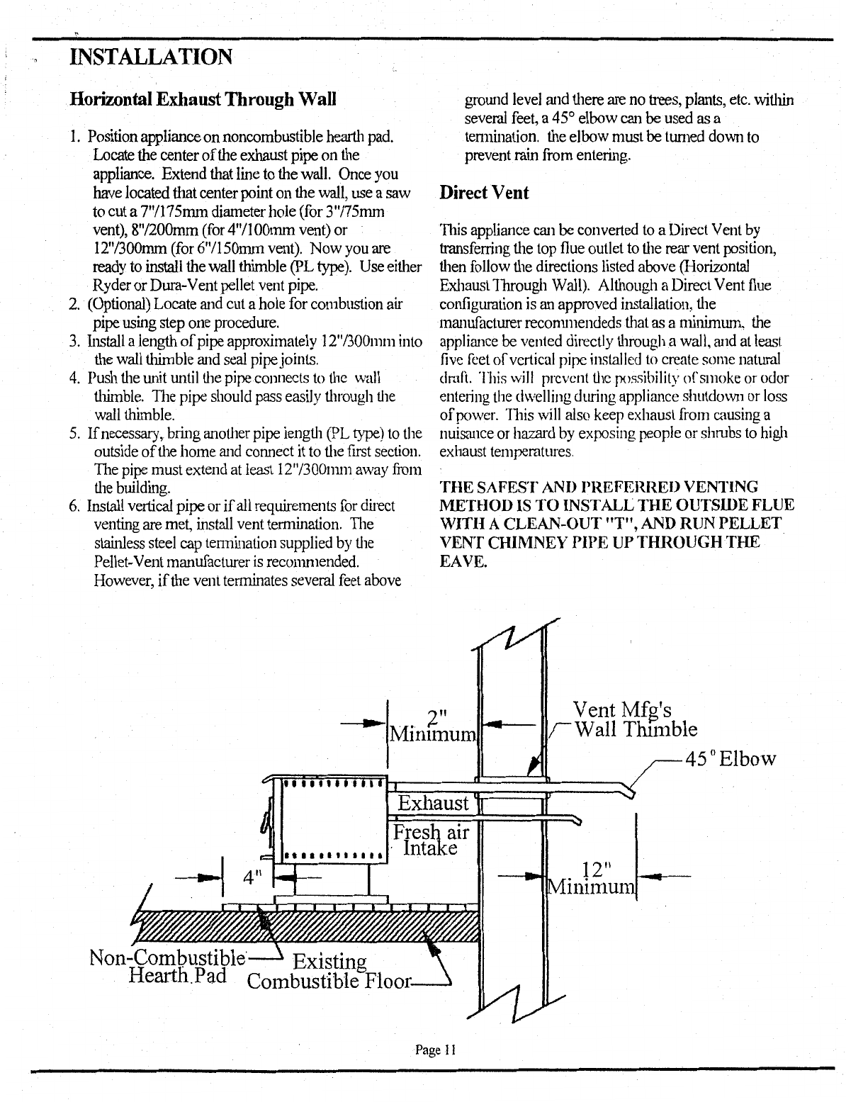
Direct Vent
This
appliance
can
be
converted
to
a
Direct
Vent
by
transferring
the
top
flue
outlet
to
the
rear
vent
position,
then
follow
the
directions
listed
above
(Horiwntal
Exhaust
1brough
Wall).
Although
a
Direct
Vent
flue
configuration
is
an
approved
installation,
the
manufacturer
recommendeds
that
as
a
minimum,
the
appliance
be
vented
directly
through
a
wall,
<md
at
least
five
feet
of
vertical
pipe
installed
to
create
some
natural
dmfl.
This
will
prevent
the
possibility
of
smoke
or
odor
entering
the
dwelling
during
appliance
shutdown
or
loss
of
power.
'J11is
will
also
keep
exhaust
from
causing
a
nuisance
or
hazard
by
exposing people or
shrubs
to
high
exhaust
temperatures.
THE
SAFEST AND PREFERRED VENTING
METHOD IS
TO
INSTALL
THE
OUTSIDE FLUE
'WITH A CLEAN-OUT
"T",
AND RUN PELLET
VENT CHIMNEY
PIPE
UP
THROUGH
THE
EAVE.
Vent Mfg's
Wall Thunble
45°Elbow
Page
II
---------------------------------------------------------------------------
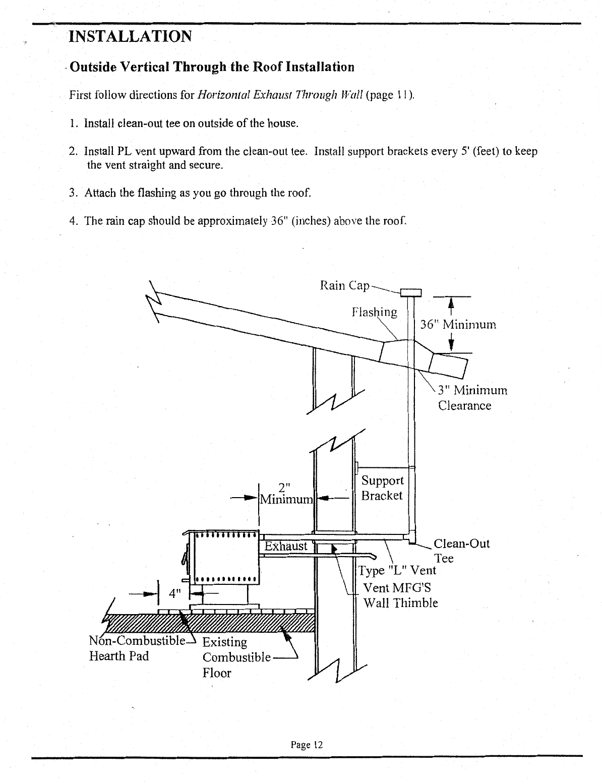
INSTALLATION
.Outside Vertical Through the RoofInstallation
First follow directions for Horizontal Exhaust
77mJUgh
1Fall
(page
II).
1.
Install clean-out tee on outside
of
the house.
2.
Install PL vent upward from the clean-out tee. Install support brackets every 5' (feet) to keep
the vent straight and secure.
3.
Attach the flashing as you go through the roof.
4.
The rain cap should be approximately 36" (inches) above the roof.
N Existing
Combustible
Floor
Page
12
T
36" Minimum
Support
Bracket
'
Clean-Out
Tee
Type
"L"
Vent
Vent MFG'S
Wall
Thimble

INSTALLATION
Inside Vertical Through the
Roof
Installation
I. Choose a stove location that is ideal. See section on Selecting a Location
2.
Install non-combustible hearth pad.
3.
Place appliance on hearth pad (vent pipe must be minimum
of3"
away from a combustible wall).
4. (Optional) Locate center
of
fresh air intake pipe on appliance. Match that center with the same point
on the wall and cut a hole approximately 2" in diameter. Install the fresh air intake pipe.
5.
Install the clean-out tee.
G.
Install pellet-vent pipe vertically. Install vent through ceiling firestop. Maintain a pipe clearance
of
3"
to combustibles and keep attic insulation away from the pipe.
7.
Extend the Pellet-vent through the roofflashing.
8.
The rain cap should be approximately 36" above the roof.
STANDARD
INSTALLATION
(RECOMMENDED)
Rain Cap
___
3"
Clearance
Use Wall Thimble
Or
Ceiling
Firestop---
r
Non-Combustible
Hearth Pad Existing
Cmnbustible
Floor
resh Air Intake
The most desirable installation is Pellet Vent pipe connected
to
the top
of
the appliance and run up
through the ceiling, then terminating above the roofline. Be sure to follow all clearances listed by pipe
manufacturer.
Page
13

INSTALLATION
The models PF70FI and PF70FIB pellet fired wood heaters are approved for installion into a masonry
fireplace or an approved factory-built zero clearance fireplace. Although the minimum venting requires
only a starter section that protrudes past the damper assembly and is sealed at that point, the manufacturer
reccommends that a full3", 4" or 6" liner (listed PL type) be installed from the appliance to termination.
Installation Into Masonry Fireplace
__,..,..~
Models PF70FI & PF70FIB
1.
Install the hearth pad
(if
necessary).
2.
Lock fireplace damper
in
open
position.
3.
Install positive flue connector at
fireplace damper.
4.
Connect an exhaust pipe section
to the flue collar exit on the top
of
the stove.
5.
Install listed PL type liner to the
top
of
the chimney (minimum
requirement is listed PL type
starter section that protrudes pas
the damper assembly and is
sealed at that point).
t
I
I
I l
I
I I
I
Existing
Front--
Surround~
I
I
v
1111
IIIII
III
*-4"--tl
c:
....
11111111
I I
w~h"
I I I I I
L.
\_In,ula6ng
Hearth
Pad
Extstmg Floor
Installation Into Factory Built Fireplace
~~
I I
I I
I I
I
I I
I I Liner
-I
-
--
I
I I
I I
I
Seal
With
Steel Plate
-
I l
I
I
i
r----·
---
H'
I
Flex Pipe connection
I I
J I
=\)
_j_
_l
d
"T'-4-
I I
-.
Tee With Clean-out
Fresh Air Intake
J
_j_
l
I I I I
The factory built fireplace must accept this appliance without modification other than removing bolted or
screwed together pieces such as smoke shelf/deflectors, ash lips, screen and door tracks, that may be
reinstalled to restore the fireplace to its original operating condition
if
this appliance
is
removed and not
replaced. Do not remove damper from fireplace. THE REMOVAL OF ANY PART MUST NOT
ALTER THE INTEGRITY OF THE OUTER SHELL OF THE FIREPLACE CABINET IN ANY WAY.
Although the minimum venting requires only a starter section that protrudes past the damper assembly
and is sealed at that point, the manufacturer reccommends that a full 3
11
, 4
11
or 6
11
liner (listed PL type) be
·installed from the appliance to termination.
Page
14

fNSTALLATION
Mobile Home Installation Requirements
Installation·
of
this appliance into manufactured
housing must follow the instructions for residential
installation, with the following supplemental
requirements
per
OAR 9I8-520-0I0 through
918-520-110:
I. Secure the appliance to the floor.
2.
Do not disturb the structural integrity
of
the
home. The chimney must provide for a section
joint so that any parts extending above
13'
6"
from ground level can be removed for
transportation
of
the mobile structure.
3.
The stove must be grounded to the mobile
home trailer frame-with a No. 8 (minimum)
solid conductor.
4.
The combustion air must communicate
to
the
outside air.
5.
Floor protection beneath the unit is required,
4"
in front, 0"
on
sides and back.
6. Structural members such as
roof
trusses or floor
joists cannot be cut
or
modified while making
the installation.
Outside Air Provision
Although this section applies to a mobile home
installation, it may also be required by local codes
in standard residential installations.
When connecting to an outside fresh air source, be
sure that the material is not PVC or plastic pipe.
Only
2"
inside diameter flexible metal ducting or
flexible high-temperature material should be used.
Steel, aluminum
or
copper pipe could be
substituted.
To provide sunicient combustion air, keep the
number
of
bends in the pipe to a minimum.
If
there
is to
be
several bends in the fresh air pipe or
if
it
is
to be
an
extended length. then 2
114"
or larger
ducting
is
recommended.
Page
15

OPERATION
ControlPanel Functions
A.
Off/On PowerSwitch
The
main
powerswitch
has
two
positions:
up
-
OFF
down
-
ON
B.
AugerI InitiateSwitch
Pressing
the
rocker
switch
upward
will
cause
the
auger
motor
to
nm
as
long
as
you
hold
the
switch
in
this
position.
This
will
shorten
the
time
needed
to
get
pellets
to
drop
into
the
frrepot,
particularly
after
filling
the
hopper
when
it
was
entirely
out
of
pellets.
Pressing
this
switch
downward
starts
a
12
minute
cycle
which
bypasses
the
snap
discs.
·n1e
L.E.D.
lamp
will
change
to
a
light
orange
color
for
this
duration.
C.
L.E.D.
(light emitting diode)
Lamp
When
this
light
is
on,
it
indicates
that
the
stove
is
operating
in
the
following
mode.
Green:
Power
ON
Red:
Cool
Down
Orange:
Start
Mode
(12
minute
cycle)
D.
Fuel Rate S""itch
This
rotary
switch
has
four
bum
rate
positions:
clockwise
for
higher
feed
rates,
cow1ter-
clockv.~se
for
lower
feed
rates.
Fuel
Rate
Setting
l.Low
2.
Medium
Low
3.
Medium
High
4.High
Fuel Delivery
*
lb.'s
per hour
fuel
delivecy
1.00
lb./hr.
2.25
lb./hr.
3.75lb./hr.
5.00
lb./hr.
*
feed
rates
are
approximations
only.
Actual
feed
rate
will
vary
depending
on
size
and
length
of
fuel
used
and
variations
in
line
voltage.
The
Room
AirBlower
increases
in speed
as
fuel
rate
increases.
TI1e
following
approximate
voltages
are
delivered
to
the
blower on
each
fuel
rate:
Fuel
Rate
Setting
Low
Medium
Low
Medium
High
High
Room
Air
Blower
Voltage
89V
97V
105V
114V
l11e
draft
fan
speed
increases
only
slightly
as
the
feed
rate
is
increased
from
low
to
high.
Fuel
Rate
Setting
Low
MediwnLow
Mediwn
High
High
Draft
Fan
Speeds
Voltage
104V
107V
IllY
114V
E.
Optional Wall Thermostat
One
way
to
maximize
the
efficiency
and
convenience
of
your
stove
is
to
install
a
remote
thermostat.
A
Iloncywell,
model
T87F
24
volt
thennostat
is
one
ofthe
many
tmilc;
available
that
is
recommended.
Follow
the
m<mufacturer's
installation
instructions
using
18/2
stat
wire.
Install
\\~re
to
appliance
by
cutting
the
transparent
jwnper
wire
leads
on
the
control
board,
then
connect
leads
to
wall
thennostat.
Once
you
have
installed
the
thennost.at,
the
fuel
rate
will
automatically
be
on
low
when
there
is
no
heat
demand.
When
the
stove
is
calling
for
heat,
it
''~II
come
on
at
the
setting
you
have
selected
\vith
the
fuel
rate
S\vitch.
Fuse~O
Page
16

MAINTENANCE
ROUTINE INSPECTION REQUIREMENTS
DISCONNECT
POWER
BEFORE
DOING ANY
MAJOR
MAINTENANCE ON
THIS
STOVE
The following areas should be inspected periodically to ensure
that
the
appliance
is
operating
at
its
optimum
and
giving you excellent
heat
value:
Firepot
I
Burner
Plate
Inspect the Firepot and Burner Plate periodically to
verify the holes are not blocked with impurities.
If
necessary, clean by removing the burner plate from
the firepot and scrape the surfaces until the holes
are clear. Inspect inner holes
ofFirepot
that they
are free
of
obstructions (buildup). Remove Firepot
and empty when buildup occurs. The cleaning
frequency will be dictated
by
the quality and
quantity
of
the fuel burned. The following
is
the
suggested schedule to establish a minimum:
Between 2 days and 2 weeks, depending on the ash
content in the fuel burned. Ash content can vary
from .25% to 1%. Using dirty fuel affects the
cleanliness
of
the
bum
and maintenance frequency.
Remove clinkers or carbon build up as necessary.
Clinkers are a byproduct
of
the fuel. Silica (or dirt)
in the fuel, along with other impurities can fuse
under heat and cause clinkering. Clinkering
is
a
function
of
the fuel, not the stove.
Ash
Pan
Gasket
and
Door
Gas){et
CAUTION: MAINTAIN GASKETS IN GOOD
CONDITION. DO
NOT
LEAVE STOVE
BURNING WITH
DOOR
OR
ASH PAN DOOR
OPEN
OR
AJAR.
It
is important to maintain
gaskets for an air tight seal.
If
the
Ash
Pan Gasket
or Door Gasket become loose over time, glue it
back into position using high temperature (RTV)
silicone sealer as an adhesive.
If
the gaskets should
become frayed
or
damaged they should be replaced.
Gasket material can be purchased from your dealer
or some hardware stores. Use same size and type
as original.
Door Gasket: 3/4" rope, medium density.
Ash Drawer: 3/8" rope, medium
or
light density.
Ash
}Jan
This
is
located under the exterior ash lip (below
door) and
is
locked with two spring latches (with
slot heads). Loosen the two slot heads on the ash
pan with a straight blade screw driver by turning
both screw heads counterclockwise. This will
release the spring latches.
Ash Removal
and
Disposal
CAUTION: BE
SURE
THE FIRE IS OUT AND
STOVE
IS
COLD BEFORE REMOVING ASHES!
NEVER BURN STOVE
WITJ-I
ASH PAN DOOR
OPEN.
Ashes can hold live embers for several days, and
must be disposed
ofwith
care. Be certain the fire
is
out and stove is cold before removing Ash Pan.
I. Brush ashes into Ash Pan.
2.
Remove ash pan and dump ashes into a metal
container with tight fitting lid. Store container
away from appliance.
3. Clean and replace Ash Pan and tighten the spring
loaded screws.
The closed container holding ashes should be
stored on a noncombustible surface, away from
combustible materials. Keep ashes in the container
until you are certain all the cinders have completely
cooled. NEVER place ashes in a cardboard box or
any other combustible receptacle. Store pellet fuel
at least 36" away from appliance.
Page
17
This manual suits for next models
6
Table of contents
Popular Pellet Stove manuals by other brands

Harman Stove Company
Harman Stove Company Pellet Pro II manual

RED
RED GARDENIA Use and maintenance manual

Breckwell
Breckwell Tradition P23FSA owner's manual

Ecotec
Ecotec Monica Plus Owners & installation manual

Breckwell
Breckwell SPG9000 Owner's operation and instruction manual

pleasant hearth
pleasant hearth PH35PS Series owner's manual


SOLZAIMA
SOLZAIMA K50 instruction manual

Palazzetti
Palazzetti ECOFIRE LOLA PRODUCT TECHNICAL DETAILS

Quadra-Fire
Quadra-Fire CB1200M-MBK owner's manual

Masport
Masport STM00739 Owners manual instructions
... owner's manual")
Quadra-Fire
Quadra-Fire MT VERNON Pellet Insert Advanced Energy (AE)... owner's manual

MCZ
MCZ CLUB Mode d'emploi