Brauniger IQ Series User manual
Operating instructions

©1998
Text: Bräuniger GmbH
Grafik and Design:
Tony W. Richter,
ars [atelier für werbedesign]
+49 8685 98 49 56

1
Two wings what next? ......................................................................Pg. 2
Starting up routine ............................................................................Pg. 2
Altimeter............................................................................................Pg. 2
Analogue Vario ..................................................................................Pg. 3
Time constants of analogue vario ........................................................Pg. 3
Digital Vario ......................................................................................Pg. 3
Time constants of average vario ..........................................................Pg .3
Speed ................................................................................................Pg. 4
TEC Total energy compensation........................................................Pg. 4
Acoustics and volume........................................................................Pg. 5
Stall-alarm............................................................................................Pg. 5
Date and time ....................................................................................Pg. 5
Memory..............................................................................................Pg. 5-6
Printer selection ................................................................................Pg. 6
Barograph ..........................................................................................Pg. 6-7
Inserting a marker ................................................................................Pg. 7
Deleting recorded flights......................................................................Pg. 7
Printout ................................................................................................Pg. 7
Pilot`s Name ......................................................................................Pg. 7
Useful information about the batteries..............................................Pg. 8
Further functions of the IQ Series
Net vario ............................................................................................Pg. 8
Entering polars ..................................................................................Pg. 9
Recording polars................................................................................Pg .9
Nominal Speed Computer..................................................................Pg .10
Flight-optimized Nominal Speed according to Mc Cready ..............Pg .10-11
Data transfer to the PC ......................................................................Pg .12
Lift/drag ratio ....................................................................................Pg .12
Link to a GPS Navigation receiver....................................................Pg .13
Wind speed and direction ....................................................................Pg. 13
Final approach calculator ..................................................................Pg .13-15
GPS access without speedsensor..........................................................Pg. 15
Miscellaneous ....................................................................................Pg. 15
Printing out the device settings..........................................................Pg .15-16
Fastening............................................................................................Pg. 16
Water landing ....................................................................................Pg .16
Guarantee ..........................................................................................Pg .16
Procedure for Official FAI Observers................................................Pg .17
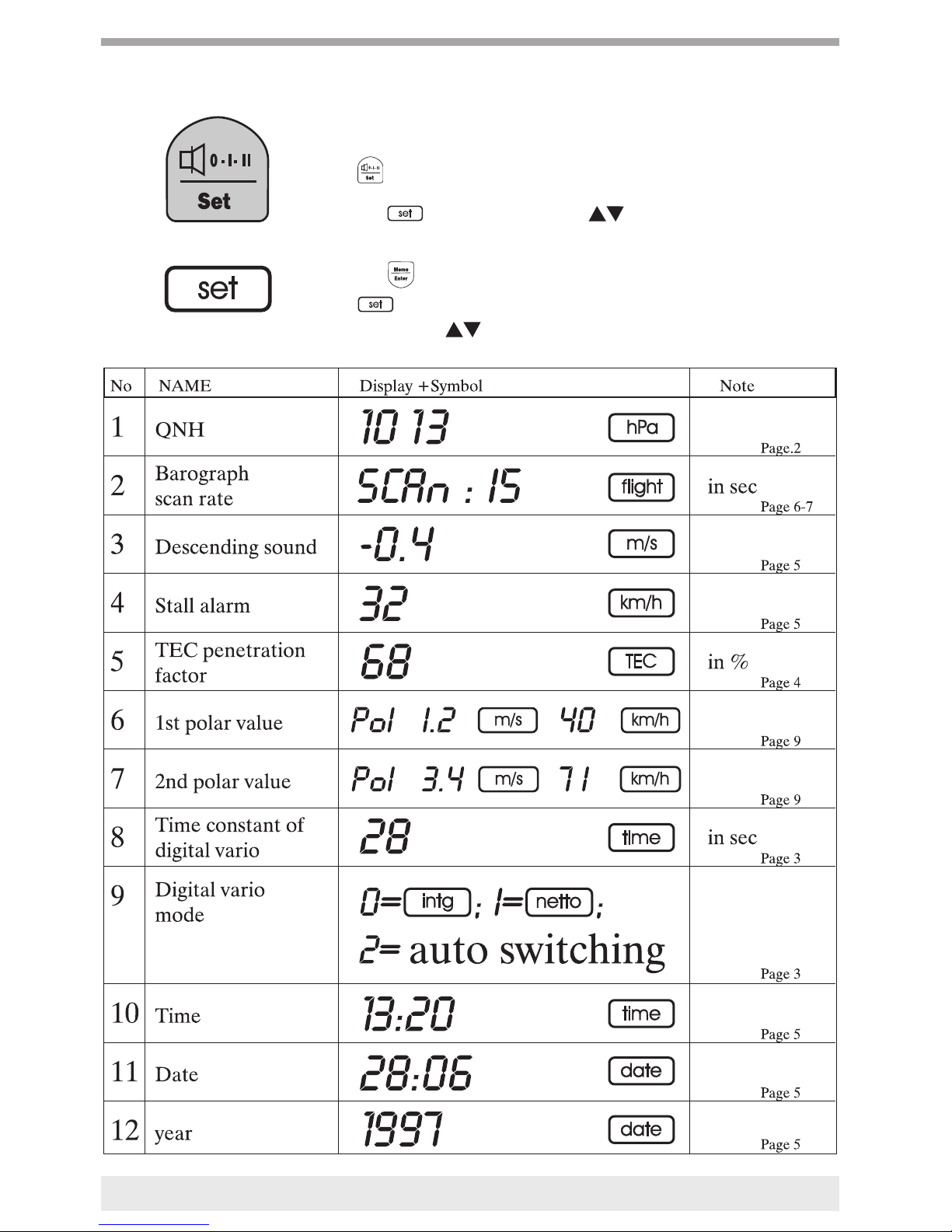
SET mode (change settings)..............................................................Pg. 18-19
NEW function ..................................................................................Pg.20
IQ Series Picture................................................................................Pg. 21
Operating Instructions IQ-Competition-GPS
Version 2.8
01. September 1998 For Hang glider
For Paraglider
Info
Attention
Table of contents
Often Pilots own more than one glider and some are paraglider as well as
hangglider pilots. For not changing ervery time all your instrument set-
tings like Polar- Stall alarme - Speed adaption - Time constants - and
more it is possible to store all values for two different sets of equipment.
Changing from Set 1 to Set 2 is made in Set Mode No. 25.
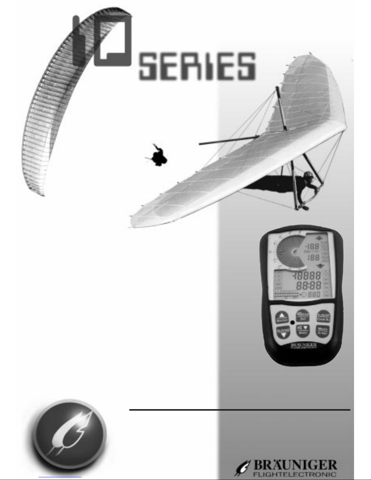
After the display-test with all segments activated for 2 sec the instru-
ment will show:
ðSerial number
ÀSet 1 or Set 2 activated
ÃDate (year - day - month)
{according FAI regulations}
ÕNumber of free memory blocks of the flight diary (max. 50)
Remaining memory for the barogrph; in hrs:min
(IQ-Compet.only)
Time interval of memory
(1-5-15-25 sec)=Baro scanrate
The unit is equipped with two altimeters and . The
key allows you to switch between them.
>> Elevation above sea level
>> Reference height - can be reset to 0 by extended pressing of
the key. When switching to the flight time (flight duration)
appears for 5 seconds, followed again by the time.
The keys are used to change the elevation or After
repeated pressing of ( SF=Special function) appears:
air pressure
temperature
This display complies with the QNH value. If the elevation
is correctly set, then the air pressure at sea level and the tem-
perature are displayed. After 5 sec. the special functons display auto
2
Two wings, what next?
Starting up routine
Altitude

matically returns to and the time. The temperature can be dis-
played either in °F or °C. (Set Mode No.15)
Altitude in meters and feet
Normally and have the same dimensions (meters or feet).
In Set Mode No.24 you can choose in meters over sealevel and
in ft over sealevel, which is very useful for UL-pilots or balloo-
ners.
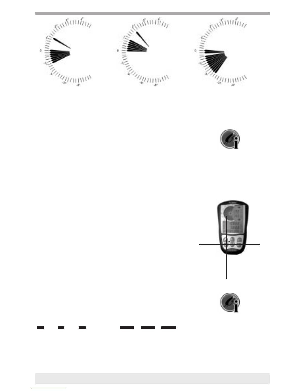
The analogue vario displays in steps of 0.2 m/s [40ft/min] . A maximum
of ±10 m/s [2000ft/min] can be displayed
The response inertia of the Variometer is determined by its time constant.
A short time constant results in a quick response, but can cause the dis-
play to be jumpy and erratic. A constant that is too long displays climbing
or sinking changes too slowly. For the Analogue vario and acoustic, a
value of 1 sec. has proven to be effective as a trusted ‘Golden Average’
(= default value). However, especially in turbulent air it can be an advan-
tage to have a longer time constant and slower vario reactions. In Set
Mode No.20 one can choose a constant from 1 to 3 sec. for analogue
vario and acoustic.
The Digital vario displays a resolution of 10 cm/s [20ft/min], and the time
constant can be adjusted by the User as a mean value variable. As a netto
vario, it can also display the status of the ambient air, or alternatively it
can be used during gliding as netto vario while climbing as an intega-
tor(=averaging vario).
The choice can be made in Set Mode No. 9.
The averaging vario is a digital vario with a much longer time con-
stant (1...30 sec.). It is very useful to find out the average value of a ther-
mal climbing. Its constant can be changed in Set Mode No.8.
This vario is also named integrating vario.
3
Analogue vario
Digital Vario
climbing 2 m/s climbing 6 m/s
ååtime constants of average vario
ååtime constant of analogue vario
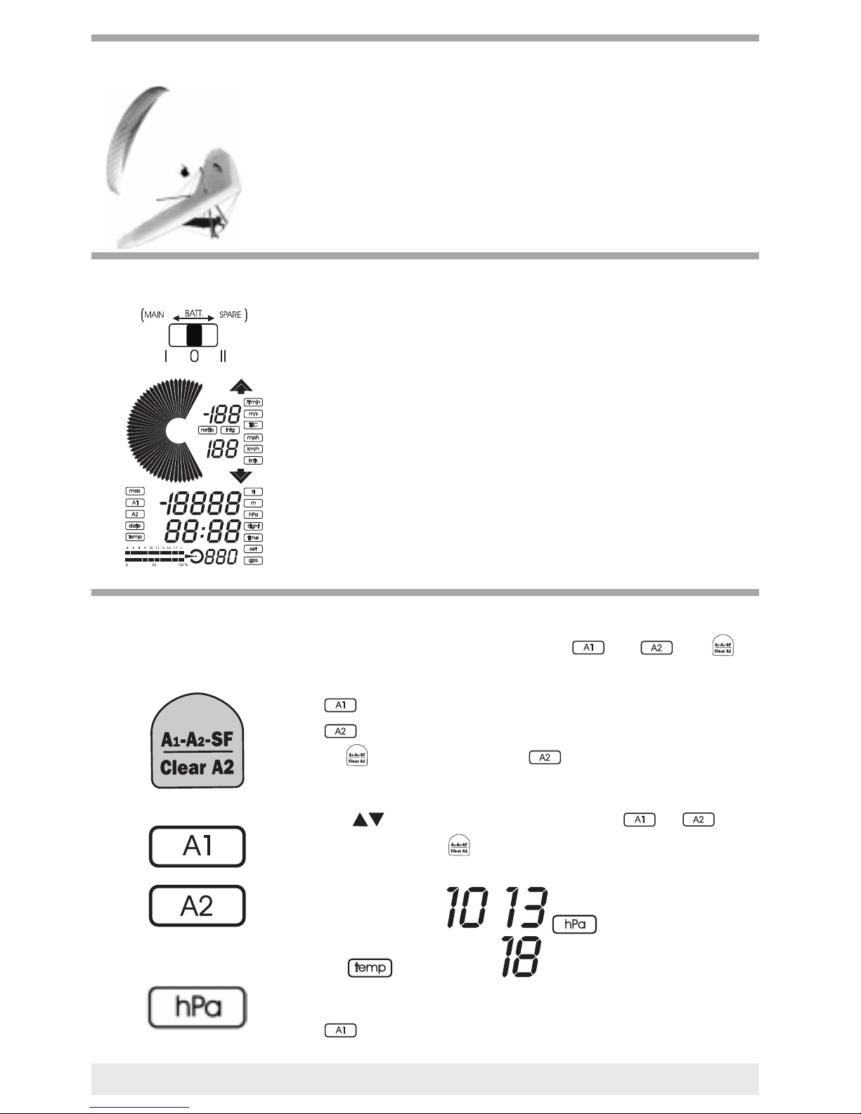
The display will indicate the speed of the flywheel sensor, which is avai-
lable as an option, and which is inserted into the socket on the right side.
A possible speed deviation caused by different positioning can be
compensated for using Set Mode No. 19.
Changing in speed is usually caused by the pilot’s steering movements.
Braking from full speeds causes a climb, which is not due to air rising. It
must therefore also not be displayed by the Variometer.
The TEC circuit will therefore pull the Variometer needle down when
reducing the speed, in an attempt to compensate for the extra elevation
gained as a result of the speed. Since the electronics are not able to dif-
ferentiate between the desired speed changes and air turbulence, a 100%
efficient Vario-display will become erratic. In accordance with the wishes
of the pilots, the TEC efficiency can be set between 0....100%.
According to our experience, 65% is a good average
The setting is made in Set Mode No. 5.
4
Speed
TEC Total energy compensation
Hang glider-sensor
Paraglider-sensor
Repeated pressing of the key makes it possible to select between
“Off - Quiet - Loud”. The sound that can be heard during this shows the
selected level. If only a short confirming bleep is heard, then the acoustic
has been switched off.
Descending sound
A short pressing of the key switches the sink acoustic on or off.
The moment the sink sound is activated you can see also it’s cut in point
at the variometer scale, changing this point is done in Set Mode No 3.
If the flywheel sensor indicates a speed below the value selected by the
user which is higher than 15 km/h [10 mph], then a loud quickly repea-
ting sound will be heard.
The factory pre-setting is for 30 km/h [17 mph].
Changing the setting is carried out in Set Mode No. 4.
If a value of 15 km/h [10 mph] is entered, the Stall Alarm is disab-
led.
The stall alarm is a great help for determining the opportune moment
for pushing out the controlbar during critical landings.
The time appears in the display area after the starting up routine.
Setting the correct time and date is done in Set Mode, using No. 10
for the time, No. 11 for the date and No. 12 for the year.
CAUTION: In the IQ Competition, the time and date cannot
be changed once a barogram has been saved (FAI regulation).
Deleting the barogram: Refer to barograph page 6.
The flight data for 50 flights are filed in the memory of the IQ unit. A
flight is only acknowleged as one if it has lasted longer than 3 minutes
and shows a height difference of more than 25m [100ft]. Memo Mode is
accessed by pressing the key. The keys can be used to flip
through the saved flight pages. The following is displayed: max. climb,
max. speed, max. height and the of the flight.
The flight number appears at the bottom right-hand side of the display.
The target appears if the barograph was activated during the flight
(competition only).
5
åå
Stall-alarm
Date and time
Memory
Acoustics and volume

In addition, it is possible to read out the max. height , max. descent
and the duration of the flight by pressing the
key.
Printing the flight list (Flight diary)
The saved flights for the IQ series (max. 50) can be output via a printer
as a flight list. The following is printed out:
-Flight number - Date - max. height - max. height 2 - max. climb - flight
duration - Barogr. scan rate.
Connect the device to the printer (connection cable is part of the standard
equipment supplied with the IQ Competition). Turn on the unit and
switch into Memo Mode using the key. The flight number 0 appears
at the bottom right-hand side.
Now hold down the key for approx. 3 sec.
>The flight list will be printed out.
It was already possible to use most available office printers with earlier
Vario models. In the IQ Series, the printer output can be set to be com-
patible with EPSON/IBM and HP printers.
The settings are made in Set Mode No. 14.
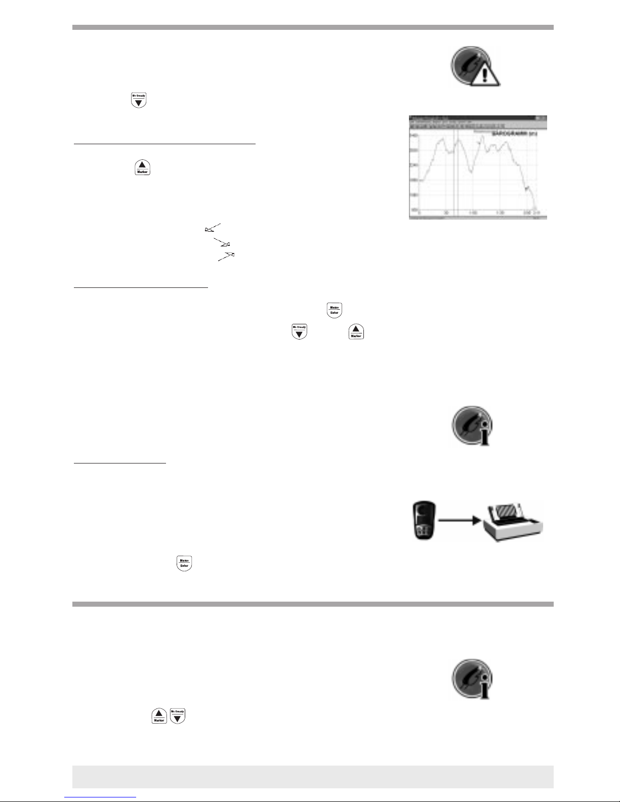
A barograph is additionally integrated in the IQ Competition series. If a
flight is to be recorded, then the flight recording process is started and
stopped by the extended pressing of . The flight time is set to 0, a
confirmation sound is audible and the symbol starts blinking.
In the IQ Competition series, the
height is saved in the memory with a resolution of 1m [3 ft] , as well as
the speed with 1 km/h [1mph].
80 hours of flight time can be recorded (max. 50 flights) using a recor-
ding interval of 15 sec.
The scan rate can be altered by the pilot in Set Mode 2.
(Factory presetting = 15 sec.)
A recording interval of 1 sec. or 5 sec. is recommended for measuring
flights when determining polar values.
Due to FAI regulations the recording interval for an acknowledged baro-
gram must be 20 sec or less. Do not use the scanrate of 25 sec if you need
FAI approval for your flight. A FAI accepted barogram must be printed
out directly to a printer (not via computer) and an official observer must
be present. (see page 20) Even if the IQ-instruments are able to measure
and memorize altitudes up to 8.000 m (26.000 ft), the official printout is
limited to 6.000 m (21.000 ft).
6
Barograph
Printer selection
Caution: If the Barograph is activated, then the height cannot be
altered.
Pressing the key switches the McCready function on. (Please refer
to page 10)
Inserting a MARKER in the Barogram
Pressing the key once is confirmed by the unit with an audible
double confirmation tone. Now a MARKER has been inserted.
In later output of the Barogram, this marker sets a reference point to a
photograph which has been taken or to a predominant landmark.
The arrows means: red arr. ( ):max. sink
green arr. ( ):max. climb
yellow arr. ( ):max. speed
Deleting the recorded flights
To clear the memory, change over into Memo Mode with
Call up flight number 0, and hold down both the and the keys
for 5 seconds. All saved flights are then deleted. A confirmation tone is
audible.
If the message “Memo Overflow” appears while printing the flight list,
then the IQ Competition memory is full.. If you still continue to record,
then the data for the oldest flight will be overwritten.
It is highly recommended, that the memory be cleared from time
to time.
Barogram Printout
The outputting of a Barogram can take place via the serial interface
(RS232), as well as via the parallel interface (Centronics). Switch the unit
into Memo Mode;
Select the desired flight from the flight list . Barograms are those flights
for which a number appears in the Baro-Scan column. The indicated
number represents the scan rate in seconds.
Extended pressing on key will start the transmission of the data
to the printer.
The manufacturer and some dealers are able to enter the pilot’s name into
the unit’s memory with the keypad.
When outputting a Barogram with a printer or on a screen, the pilot’s
name will already be contained in the print-out.
One can write up to 25 letters into the unit. This is made in Set Mode
No.18. With the buttons the name is entered letter by letter
in ASCII code.
A marker is displayed with
an small circle in the curve.
7
Pilot’s name
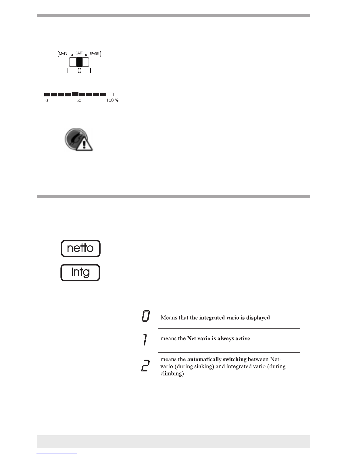
The new IQ Series offers a much more efficient utilisation of the battery
capacity. We recommend that two 1.5V alkaline cells, sizeAA (Mignon)
be used for the main battery. All IQ Series units are additionally equip-
ped with a second battery set; comprising of 2 alkaline cells, size AAA
(Micro).
When the voltage in the main battery drops, it is possible to switch over
to the second batteries without any interruption.
The battery capacity for the active battery is constantly monitored in the
lower graphic display (bar graph).
Operating times of approx. 100 hours are achieved if quality alkaline
cells are used.
Caution: The memory and clock just work with the second bat
tery set. In case of changing the second set you have to run the
vario with the main battery then changing the second set. Now
your saved flights will still be in the memory.
In contrast to normal varios in which the up/down movement of the pilot
is displayed, the Net-Vario displays the rise or fall of the ambient air.
This only works, if a polar has been saved and if the speed sensor is in
use during the flight.
As the display should always show “0” during quiet air conditions, and
regardless of how fast the pilot may be flying, this function can be used
efficiently to check the entered polar. The Net-Vario is really effective for
the purpose of utilising a upwards thermal current if a decision must be
made to continue or cancel a high-speed flight.
The Net-Vario is a digital vario that is activated in Set Mode
No. 9. It offers the following choices:
8
Useful informations about batteries
Net - vario (digital vario)
Further functions of IQSeries
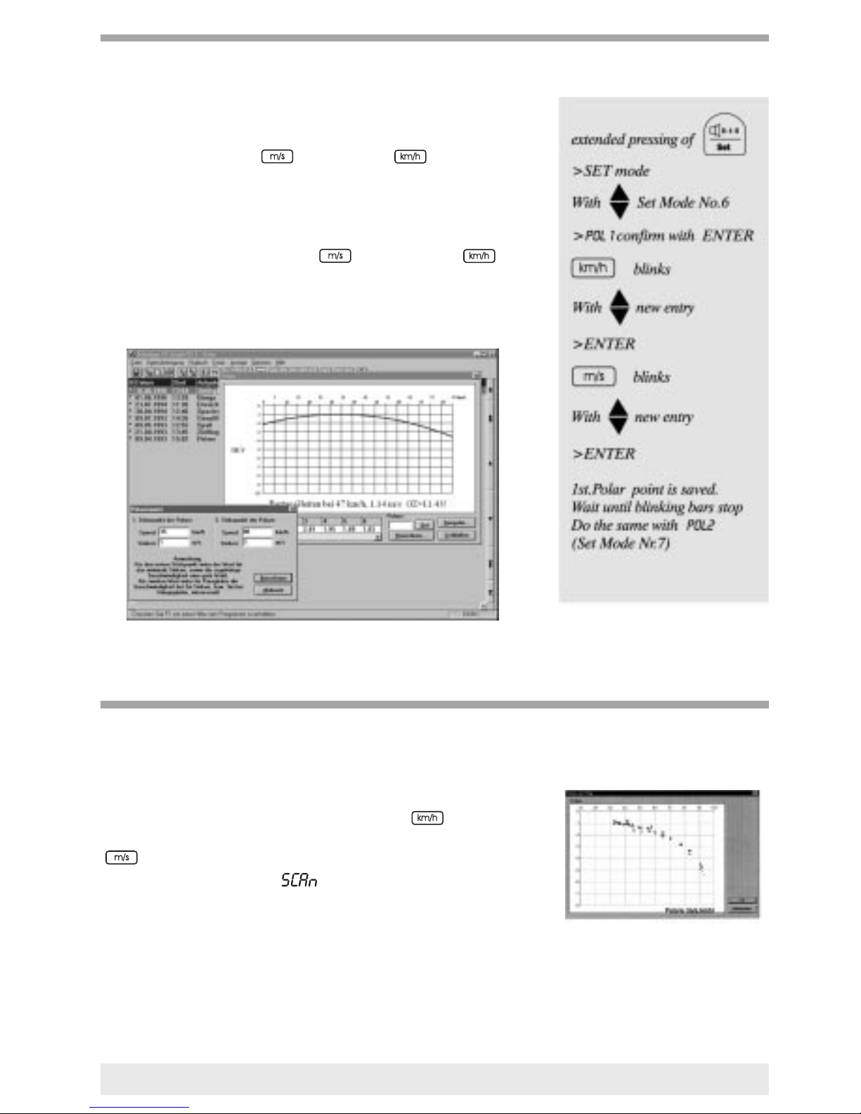
Only two polar points may be entered.
Item 1 is minimal sink rate and the approriate speed;
e.g.
POL 1 1.0 35
at this point, the polar runs horizontally.
Item 2 is a point within the upper speed range;
e.g.
Pol 2 3 80
Inputting is made via Set Mode No. 6 and 7 All other points of the
polar are automatically calculated by the instrument.
Setting the polar in the PC-Graph
Since only 2 points may be entered, it is not too difficult to find these
two pairs of values.
We would recommend that a day be selected that is absolutely wind-free
and free of thermal climbing and that both speeds are flown over
an extended period of time, while bearing the appropriate descent values
in mind. A polar flight can be carried out with the IQ
Competition. The scan rate ( ) of the Barograph must be set to 1
sec. (Set Mode -No.2) during this. During the test flight, various speeds
must be maintained
at a constant (± 2km/h).for a minimum of 12 seconds.
With the help of the PC Graph Program various points of the polar
can then be viewed and printed out as a graphic illustration
ÌÌin any case the polar points have to be entered manually.
Hang glider polar (CUT)
9
Entering of the polar
Recording polars
makes it possible for the pilot to make alterations in the current descent
by adapting the flight speed by flying quicker or slower, so that his glide
is optimized. This will allow him to reach the other side of the valley at
the highest possible point or let him fly a maximum distance over flat
areas.
The arrow symbols have the following meaning:
This works only if the speed sensor is connected and a Polar is entered.
The difference between the optimal speed and the appearance of the
arrows can be set individually;
··for one arrow in Set Mode No.22
we suggest for paragliders 2-3 km/h
and for hanggliders 3-4 km/h.
··double arrow in Set Mode No.23.
we suggest for paragliders 6 km/h
and for hanggliders 10 km/h
1st. step: extended pressing of -> will flash
2nd. step: Pressing on activates or deactivates the McCready
function.
The normal vario sink will continue to be displayed in the sink area of the
analogue vario. In the climbing area of the vario, however, an individual
‘live’ McCready indicator will be blended in. The displayed value in the
vario scale complies with the McCready ring setting (expected climb of
1m = +1m/s): The value is calculated internally from a total of the rea-
dings from the net-vario and the speed.
In other words: If the pilot is flying in sinking air, then the
pointer will reverse. Increasing the speed causes the pointer to rise again
and to ultimately return to the original value. Or if flying into gently
rising air, the pointer will rise upwards. The old pointer setting must
again be attained by reducing the speed.
10
Nominal speed computer
Flight optimized nominal speed Mc Cready
fly much faster at least 6 km/h at least 10 km/h too slow
a little faster 2...6 km/h 3...10 km/h too slow
no Arrow> Hold speed ok ±2km/h ok ±3km/h
a little slower 2...6 km/h 3...10 km/h too fast
fly much slower at least 6 km/h at least 10 km/h too fast
The acoustics are also linked to the pointer setting; it is therefore not
necessary to keep the pointer in view constantly. Changing the speed is
sufficient to regain the acoustic sound, in the event that it’s frequency has
changed.
When compared with other McCready indicators, the major advan-
cement is that the device does not need to be touched manually to
change the ring setting. A change in the flying speed is sufficient.
Another practical example: A pilot is crossing a valley and
expects a thermal with a climb of 3 m on the other side. Consequently he
will continue to increase his speed until the required travel pointer is at
+3 m/s. This matches the McCready ring setting of 3 m. During the flight,
however, he recognises that he is losing too much height and is in danger
of not being able to get over the crest. With the old McCready he would
have manually needed to turn the ring on the vario, to enter a lower set-
ting. In the IQ series, however, it is sufficient if the speed is reduced until
the display reaches the new ring value that is needed. In extreme cases,
travel can be reduced until the pointer setting is at ‘0’, in order to then
be able to gain as much height as possible with the best glide.
A pilot should never fly with a negative McCready ring value. This
happens when he flies too slow in strong descending air. To minimise the
loss of height and time a special sound interval will be heard to remind
the pilot: “go faster “
Once the pilot reaches the expected thermal at the end of a gliding stretch,
the device switches over to normal vario-acoustic by itself, once the vario
display is within the climbing area. In spite of this the McCready pointer
remains visible.
The acoustic signal during the McCready glide consist of short
sounds and longer pauses. The normal Vario acoustic signal consists
of longer sounds and short pauses. The differentiation is obvious.
Mc Cready acoustic Vario - climbing acoustic
Once the pilot leaves the thermal, the device automatically switches into
McCready travel after a pre-set time of continuous sinking (Factory set-
ting = 7 sec; in Set mode No.13).
11
McCready Ring = 1,2 m/s
device sinking = -1,4 m/s McCready Ring = 2 m/s
device climbing = 1 m/s Pilots flying with negative McC.
ring, he’s wasting height and time.
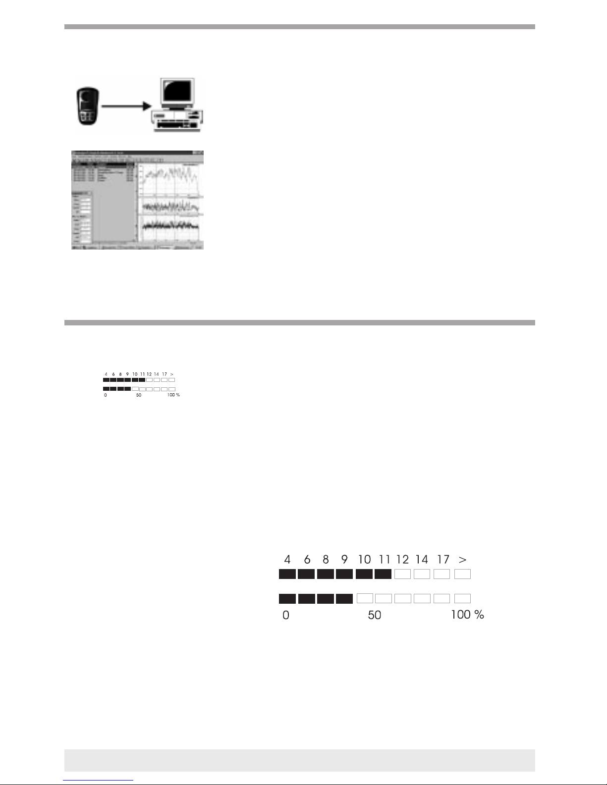
With the IQ-Competition vario it is possible to transmit flight details
to an IBM-compatible PC. A connection cable to the serial interface on
the computer (COM1/COM2) as well as the Barograph
Software PC-Graph (DOS or Windows) are needed for this purpose.
Both of these can be supplied at a very reasonable cost.
The following can be displayed on the PC screen:
Barograms, Variograms and Speedograms, each with zoom function. The
first cursor is used to directly display actual time, flight height and speed.
The second cursor displayed the time difference, heightdifference, aver-
age climb/descent and the average speed.
Illustration of Polars.
Statistical evaluation of many flights during a flying year. Inputting of
additional information such as starting and landing points, etc.
Outputting of diagrams or lists on the computer printer.
The definition is the lift/drag ratio for the covered route divided by the
descents. Or without making major errors: Speed divided by the descent.
(Both values in equal units)
If an instrument equipped with a speed sensor belonging to the IQ Series
is used, then the current lift/drag ratio as is a result of airspeed divided by
average vario and constantly displayed in the upper row of bars.
However, this display is not all that informative, as it is subject to con-
stant changes, exactly like the descent.
If a comparison between the required and flyable lift/drag ratio is
needed, further important information is provided by the two exi-
sting rows of beams in the final approach calculator.
For example: lift/drag ratio 11 and Battery 40%
12
Data transfer to the PC
Lift/drag ratio
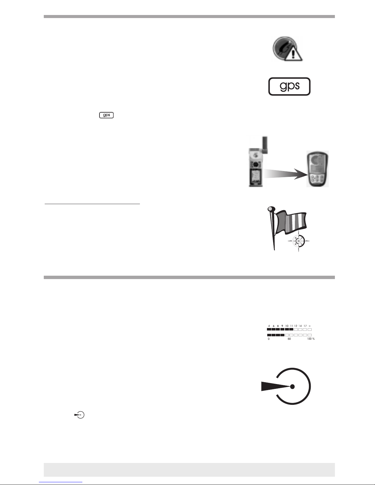
TIP: Prior to attaching the vario to the GPS device, its data output
must be set to NMEA/NMEA.
The IQ Competition GPS can be connected to any generally available
GPS receiver, and can use a variety of information from the GPS. In prin-
ciple, all GPS receivers are suitable for use with standard NMEA 183
interfaces, however manufacturer-dependant differences are known.
At the moment in which the IQ Competition receives valid signals from
a GPS receiver, the symbol*. appears. The device can determine
head or tail wind components based on the difference between the speed
over ground and the air speed. The required travel arrow as well as the
Mc Cready displays take this into consideration based on the entered
polar.
This means, that flying by the McCredy Ring 0 always guarantees
the furthest overground flight, regardless of which direction the wind
is blowing from.
Wind - speed and wind - direction
The GPS-Receiver is transmitting a new value for speed over ground
every 2 seconds and also the flight direction. Internally in our instrument
we have divided a complete compass-circle into 12 sectors of 30 degrees
each. Whenever a pilot is turning slowly (24 sec for one circle, he has
to stay in every 30° sector for at least 2 sec.) the display for time auto-
matically shows wind direction alternating with wind speed.
Once the GPS receiver transmits usable data concerning the distance to a
target point or landmark, both graphical bars receive new information.
The lower bar graph displays the lift/drag ratio which is required to
reach the target. The lift/drag ratio is calculated based on the distance to
the target divided by the current difference in height. The higher one
circles, the smaller the required lift/drag ratio will be. The upper bar
displays the flyable lift/drag ratio (not the current one). This is depen-
dent on the polars, the wind, the flying speed (only during gliding!) as
well as the flying direction with regard to the wind direction.
In simple words: It is only possible to fly off if the upper bar is at least
as large as the lower bar.
The target symbol will appear, if- because of the average climbing-
the right height (target is as fast as possible within reach) for departure is
reached. That means it should be flown by flight optimized nominal
speed. If however the pilot flies with best glide he will get more height
reserve.
*The gps-Symbol blinks as long as
the GPS receiver hasn’t found his
position.
13
Link to a GPS Navigation receiver
Final approach calculator
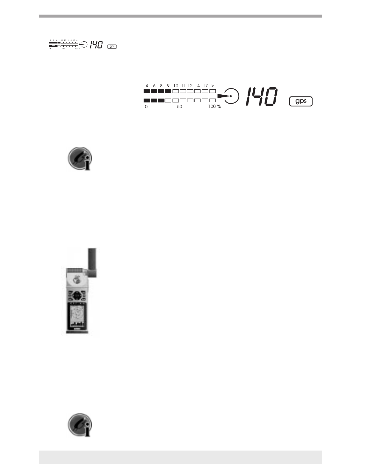
The pre-calculated height (-990...990m)[-3000...3000 ft] at which one
will reach over the target is the most interesting value in the GPS row
on the Vario. This is based on the assumption that the rising and falling
of air masses on route will cancel each other out. This is a type of secu-
rity height, which one must keep in mind during the approach.
For example: required L/D=8: possible L/D=9;
height above targetl 140 m [1400 ft]
By experience we know that especially crossing a wide valley the mov-
ment of air is not balanced usually there is more tendency to sinking air.
As an offset to this tendency one can choose (in Set Mode No.21) an
additional safety value which is taken into account to the calculated secu-
rity height (default = 20 m [65 ft] for each km distance to thetarget).
Pilots who like the risk will reduce this value to 0 however pilots who like
to arrive surely will increase the default to 30 m [90 ft] or more.
If this security height becomes smaller as a result of the sinking air, then
the McCready Ring setting 0 can be used to continue flying with an opti-
mal glide. If the security height becomes negative, then the target
cannot be reached without additional air climbing.
If, however, the security height continues to increase, it is possible to fly
faster to save time.
In order to utilise this final approach calculator during competitions
or regular flights, the route is divided into several way points, which are
entered into the GPS receiver as the route. In most GPS receivers, one
can allocate route point names consisting of 6 digits . This name will also
be continuously transmitted to the vario by the GPS. The vario is only
able to calculate the required lift/drag ratio if it knows the elevation for
the target point.
The route point names must therefore be entered in such a way that they
consist of 3 letters and 3 numbers.
Example: Laber 1680 m[5340 ft]
is to be entered: Lab168[Lab053]
or Target 600 m[1800 ft] is to be entered: TGT060 [TGT018]
or Zugspitz initial upwards thermal current 2040 m [6120 ft]
is to be entered: ZUG204 [ZUG061] etc.
In most cases, the route lists with the appropriate coordinates and eleva-
tion information can be prepared on the PC and simply transferred to the
GPS receiver.
Bräuniger GmbH has such lists available, and would be pleased to
pass these on to you.
14

As the current GPS receivers only update your data every 2 seconds,
we recommend the calculated results only be observed while circling
gently or during the approach. If the flying direction deviates for more
than 30 seconds from the direct line of the approach, (± 20° ), then the
security height indicator starts blinking.
Caution: In this case the currently displayed value is
calculated without wind influences.
GPS access without air speedsensor
Especially pilots of paragliders don’t like to fly with the trailing speed-
probe. Nevertheless the informations of the GPS receiver like: Speed over
ground - distance to goal - flight direction still could be used for full fun-
ction of the final approach calculator. In this case the instrument assumes
that the airspeed is constantly the speed of best glide ( according to the
polar ).
The two barscales show:
Possible L/D ratio (wind and polar depending)
Required L/D ratio (depending of distance and height difference to goal)
also the target symbol and the precalculated height at which one will arri-
ve over the target are active. The speed-display of the vario repeats the
GPS-speed over ground; the symbol for speed dimension blinks.
Similar to recent processor-controlled flight instruments, the
IQ Series allows permits fine adjustments to be carried out subsequently
via the software:
Inputting or changing the pilot name
Changing the amplification of the Variometer
Changing the zero point on the Variometer
Changing the temperature offset
As errors in the setting options are possible, we would request you to
contact your dealer or the manufacturer if this should occur.
The IQ Classic can be updated into an IQ Competition or IQ
Competition GPS.
Although the operations on the IQ Series are usually restricted to ON and
OFF operations during normal flying (possible setting of height), nume-
rous setting are possible which comply with the various requests from
pilots. 15
Miscellaneous
Printing out the device settings

A summary of all device settings can be listed with a printer as
follows.
Connect printer; Switch device to Memo Mode 0;
Press key; “LIST” appears
Extended pressing (approx. 4 sec.) of starts the output of the devi-
ce settings.
At present, there a variety of possibilities for attaching the instrument on
the pilot or the glider.
To find the proper fastener, make some enquiries to your dealer or
the manufacturer.
In the event of landings on water, the unit must be
opened and the batteries should be removed immediately. Upon
contact with salt water, the electronics in the unit must immediately
be thoroughly rinsed with fresh water, then the unit must be dried
carefully!!
(If the sun or a hair-drier etc. are used, the temperature must not exceed
70°C [158°F] )
Our units are guaranteed for a period of 12 months..
If service is needed, the unit can be sent to the nearest Bräuniger Support
base or directly to the manufacturer.
16
Fastening
Water landing
Guarantee

1. At the starting point
The observer ascertains, whether the unit is in order and that both seals
on the reverse are not damaged.
The observer switches the unit on and checks the serial number,date
and year, which are displayed during the start up routine. Also the dis-
played time must be correct.
The pilot or the observer set the current flight departure elevation on
the unit. The observer switches the Barograph on.. From this moment
onwards, neither the time/date nor the elevation can be changed. In addi-
tion to his normal notes such as the pilot’s
name, starting time, etc., the observer must also make note of the serial
number of the unit.
2. After the landing
the pilot stops the registration of the Barograph and switches the unit
off.
3. Barogram Print-out
The observer must first ascertain that the unit and both seals on the
back are undamaged , and that the serial number of the Barograph mat-
ches with that of the starting point
The observer switches the unit on and checks the serial number, date
and time which has been displayed during the starting up routine.
The Barograph is now connected to the printer. The observer ensures that
this is the only data line which leads to the printer. The pilot or obser-
ver initiates the print-out.
The observer must be present during the printing and must ascertain
that
a) the indicated number for the “serial-number” is identical with the seri-
al number of the unit.
b) the recognisable information contained in the print-out such as the
Baro starting time, the date and the flight departure height coincides with
the records made by the observer at the starting point.
c) the time/date shown under the “Time at Printout” are accurate.
The observer confirms the accuracy of the above points by signing
the barogram and entering his observer number.
FAI
17
Procedure for official FAI observers
A certain number of device’s features have been kept variable in order to
fully utilise the diverse possibilities offered by your instrument, and to
guarantee the individual implementations. In SET Mode, pressing the
key for 3sec. initiates access.
The symbol appears>>, the keys are used to call up various
setting one after another;
The key must be pressed if one wants to change the settings. The
symbol then starts blinking. The appropriate value can be changed
by using the keys.
18
Set mode
Table of contents


