ECS 3.8L MS200 User manual


Preface
i
Preface
Copyright
This publication, including all photographs, illustrations and software, is protected
under international copyright laws, with all rights reserved. Neither this manual, nor
any of the material contained herein, may be reproduced without written consent of
the author.
Version 1.0
Disclaimer
The information in this document is subject to change without notice. The manufac-
turer makes no representations or warranties with respect to the contents hereof and
specifically disclaims any implied warranties of merchantability or fitness for any
particular purpose. The manufacturer reserves the right to revise this publication and
to make changes from time to time in the content hereof without obligation of the
manufacturer to notify any person of such revision or changes.
Federal Communications Commission (FCC)
This equipment has been tested and found to comply with the limits for a Class B
digital device, pursuant to Part 15 of the FCC Rules. These limits are designed to
provide reasonable protection against harmful interference in a residential installa-
tion. This equipment generates, uses, and can radiate radio frequency energy and, if
not installed and used in accordance with the instructions, may cause harmful inter-
ference to radio communications. However, there is no guarantee that interference
will not occur in a particular installation. If this equipment does cause harmful
interference to radio or television reception, which can be determined by turning the
equipment off and on, the user is encouraged to try to correct the interference by one
or more of the following measures:
• Reorient or relocate the receiving antenna
• Increase the separation between the equipment and the receiver
• Connect the equipment onto an outlet on a circuit different from that to
which the receiver is connected
• Consult the dealer or an experienced radio/TV technician for help
Shielded interconnect cables and a shielded AC power cable must be employed with
this equipment to ensure compliance with the pertinent RF emission limits govern-
ing this device. Changes or modifications not expressly approved by the system’s
manufacturer could void the user’s authority to operate the equipment.
Trademark Recognition
Windows®VISTA/7 are registered trademarks of Microsoft Corp.
Other product names used in this manual are the properties of their respective
owners and are acknowledged.

ii
Preface
Canadian Department of Communications
This class B digital apparatus meets all requirements of the Canadian Interference-
causing Equipment Regulations.
Cet appareil numérique de la classe B respecte toutes les exigences du Réglement sur
le matériel brouilieur du Canada.
Declaration of Conformity
This device complies with part 15 of the FCC rules. Operation is subject to the
following conditions:
• This device may not cause harmful interference, and
• This device must accept any interference received, including interfer-
ence that may cause undesired operation

Preface
iii
SafetyInstructions
Your system is designed and tested to meet the latest standards of safety for informa-
tion technology equipment. However, to ensure your safety, it is important that you
read the following safety instructions.
Settingupyour system
• Read and follow all instructions in the documentation before you oper-
ate your system.
• Do not use this product near water or a heated source such as a
radiator.
• Set up the system on a stable surface.
• Openings on the chassis are for ventilation. Do not block or cover these
openings. Make sure you leave plenty of space around the system for
ventilation. Never insert objects of any kind into the ventilation open-
ings.
• Use this product in environments with ambient temperatures between
0°C and 40°C.
• If you use an extension cord, make sure that the total ampere rating of
the devices plugged into the extension cord does not exceed its am-
pere rating.
Careduringuse
• Do not walk on the power cord or allow anything to rest on it.
• Do not spill water or any other liquids on your system.
• When the system is turned OFF, a small amount of electrical currentstill
flows. Always unplug all power, modem, and network cables from the
power outlets before cleaning the system.
• If you encounter the following technical problems with the product,
unplug the power cord and contact a qualified service technician or
your retailer.
• The power cord or plug is damaged.
• Liquid has been spilled into the system.
• The system does not function properly even if you follow the
operating instructions.
• The system was dropped or the cabinet is damaged.
• The system performance changes
The warranty does not apply to products that have been disassembled by
users

iv
Preface
Safetycautionsandwarnings
Optical Drive Satety Information
CAUTION:
Invisible laser radiation when open. Do not stare into beam or view
directly with optical instructions.
WARNING:
Makeing adjustments or performing procedures other than those speci-
fied in the user’s manual may result in hazardous laser exposuer. Do
not attempt to disassemble the optical drive. For your safety, have the
optical drive serviced only by an authorized service provider.
Optical drive sold with this system contains a CLASS 1 LASER PRODUCT.
Product disposal notice
INPORTANT:
This symbol if the crossed out wheeled bin indicates that the product
(electrical and electronic equipment) should not be placed in munici-
pal waste. Check local regulations for disposal of electronic products.
Nordic Lithium Cautions (for lithium-ion batteries)
CAUTION:
Danger of explosoin if battery is incorrectly replace only with the same
or equivalent type recommended by the manufacturer. Dispose of used
batteries according to the manufacturer’s instructions.
Product disposal notice
1. Do not place this product underneath heavy loads or in an unstable
position.
2. Do not use or expose this product around magnetic fields as mag-
netic interference may affect the performance of the product.
3. Do not expose this product to high levels of direct sunlight, high-
humidity or wet conditions.
4. Do not block the air vents to this product or impede the airflow in
any way.

v
TT
TT
TABLE OF CONTENTSABLE OF CONTENTS
ABLE OF CONTENTSABLE OF CONTENTS
ABLE OF CONTENTS
Preface i
Chapter 1 1
IntroducingthePC 1
Introduction......................................................................................1
Specification......................................................................................2
FrontandRearI/O............................................................................3
PackingContents..............................................................................5
Chapter 3 11
UsingBIOS 11
AbouttheSetupUtility................................................................11
The Standard Configuration..............................................11
Entering the Setup Utility...................................................11
UsingBIOS......................................................................................12
Standard CMOS Setup......................................................13
Advanced Setup.................................................................15
Advanced Chipset Setup....................................................17
Integrated Peripherals.......................................................18
Power Management Setup.................................................19
PC Health Status................................................................20
Frequency/Voltage Control................................................21
Load Default Settings.........................................................23
Save & Exit Setup...............................................................23
Exit Without Saving............................................................23
Chapter 2 77
77
7
SystemQuickInstalling...................................................................7
Installing thePC 7

vi
Chapter 4 2525
2525
25
UsingtheSoftware 25
AbouttheSoftwareDVD-ROM/CD-ROM.................................25
Auto-installingunderWindows7...............................................25
Running Setup....................................................................26
ManualInstallation........................................................................28
UtilitySoftwareReference............................................................28

1
Introducing the PC
Chapter 1
Introducing the PC
Introducting
Thank you for choosing 3.8L MS200 of great performance and with stylish and
flexible design.
Support Intel®Socket LGA1156 Core i3/i5 Clarkdale processors and a dimension of
270mm (H)* 205mm (D)* 70mm (W), 3.8L SFF provides the features of low power
consumption (working with a 120Watt power adaptor), low noise (<30db) and space
saving. The chipset is Intel®H55, supporting up to 8 GB of system memory with
DDR3 memory SO-DIMM, 3.5” SATA II HDD, Slim DVD Super-multi Tray type/
Tray-load Slim type ODD, and Build in Intel® HD Graphics.

2
Introducing the PC
Specification
• Support Slim DVD Super-multi Tray type
• 120W power adaptor
WARNING:
Please realize that there is a certain risk involved with overclocking, Includ-
ing adjusting the setting in the BIOS, or using the third-party overclocking
tools. Overclocking may affect your system stability, or even case damage
to the components and devices of your system. It should be done at your
own risk and expense. We are not responsible for possible damage casesd
by overclocking.
Chipset
CPUSupport
Graphics
Storage
ODD
Power
Dimensions(mm)
Memory
FrontPanel
RearPanel
OS Support
• Intel®H55
• Socket LGA1156 for Intel®Core i3/i5 Clarkdale
processors (up to 73W)
• Built-in Intel®HD graphics
• Supported 1 x 3.5” SATAII HDD
• 4 x USB
• 1 x D-Sub, 1 x HDMI
• 1 x 10/100/1000 LAN RJ45
• 1 x TV Tuner (optional)
• 1 x Antenna (optional)
• 8 Channel Audio, 6 Jacks
• 270mm*205mm*70mm
• 2 x SO-DIMM up to 8 GB
• 4 x USB2.0
• 1 x Headphone output
• 1 x MIC-IN
• 1 x Multi-card reader slot
• Hardware Compatible with Windows 7
Expansion • 1xMiniPCIE
3
Introducing the PC
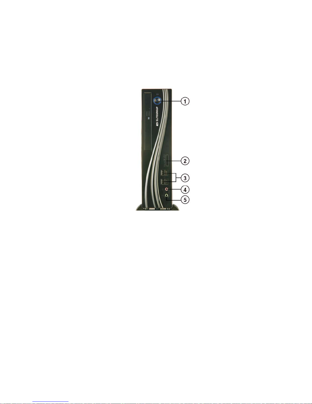
Frontand RearI/O
1. Power Button Press the prower button to turn the system on and
off.
2. 4 IN 1 Card
Reader Supports SD Card/ MMC Card/ MS Card. You can eas-
ily read phone or other files on the momery card.
Your digital cameras, DVs, MP3 players or other digi-
tal devices are highly compatible.
3. USB Connectors The USB connectors is for attaching USB devices,
such as mouse, keyboard, printer, scanner and other
USB-compatible device.
4. Mic In Jack Connecting Microphone.
5. Headphone Jack Connecting Headphone.
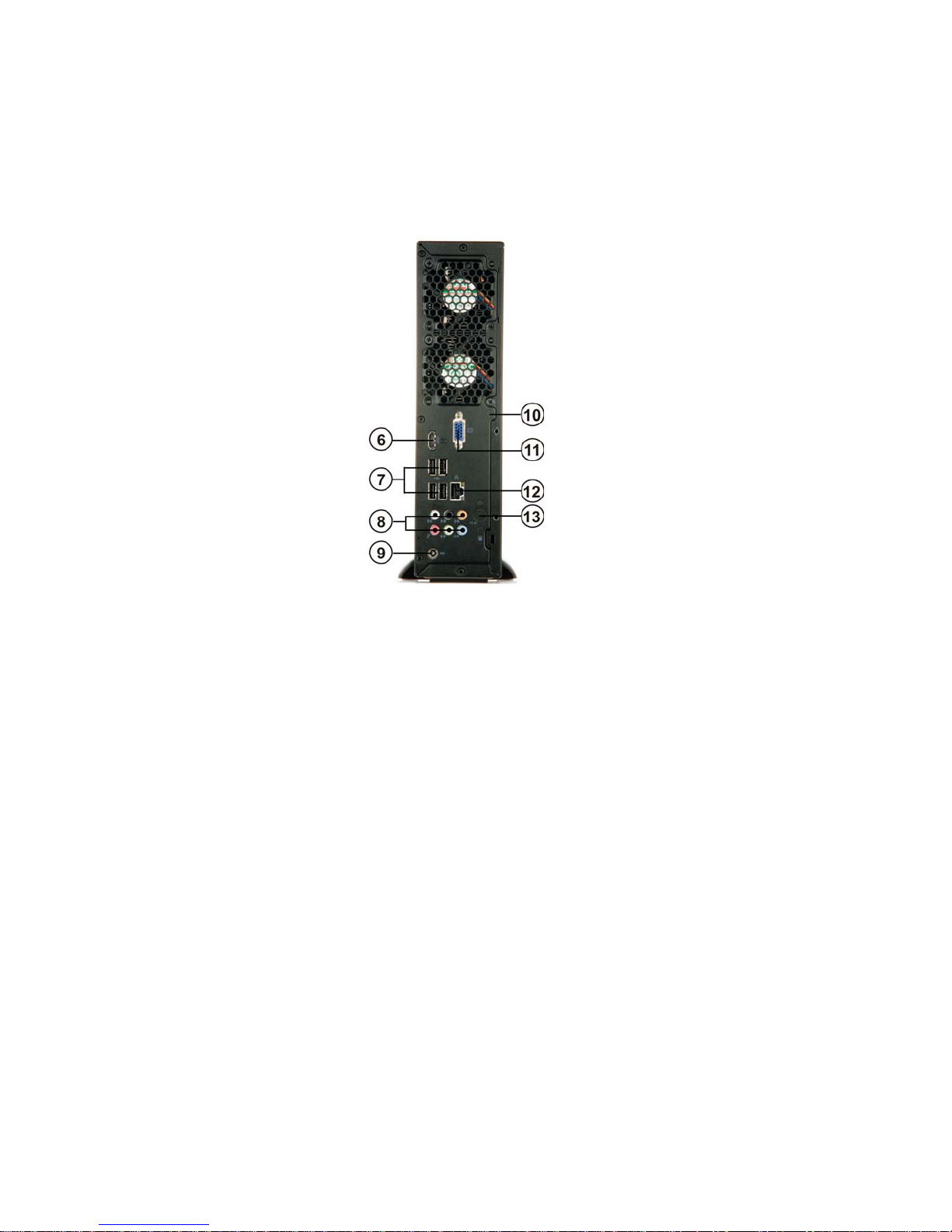
4
Introducing the PC
7. USB Connectors Connecting USB Devices (USB2.0 Ports)
12. LAN Connecting the Network.
8. Eight channel HD
Audio Microphone Jack/ Headphone Jack/ Line In Jack.
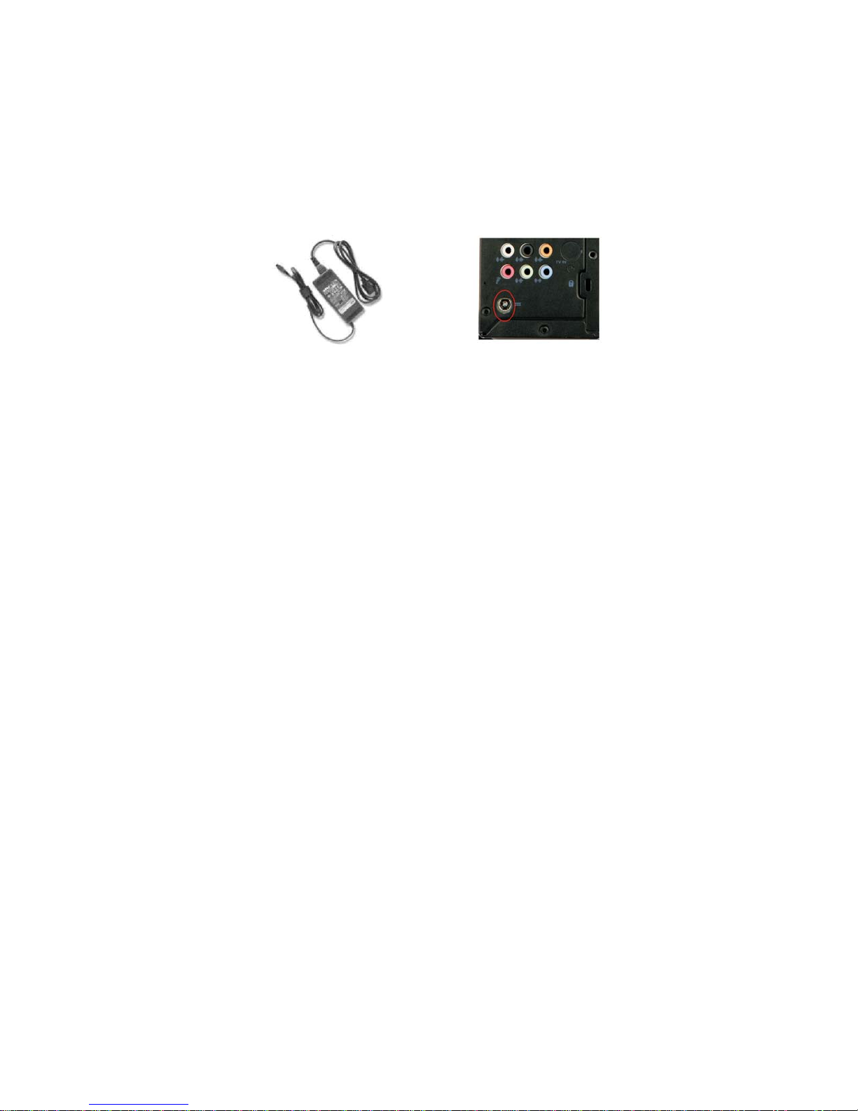
9. DC Jack It is used for power adapter
6. HDMI Connector Connecting HDMI Device.
11. D-SUB Connector Connecting VGA Monitor.
13. TV Tuner
(optional) TV in jack.
10. Antenna It is used for an optional antenna

5
Introducing the PC
PackingContents
NOTE:
Please contact us immediately if any of the items is damaged or missing.
Driver DVD Manual
Stand Power

6
Introducing the PC
Memo
7
Installing the PC
Chapter 2
Installing the PC
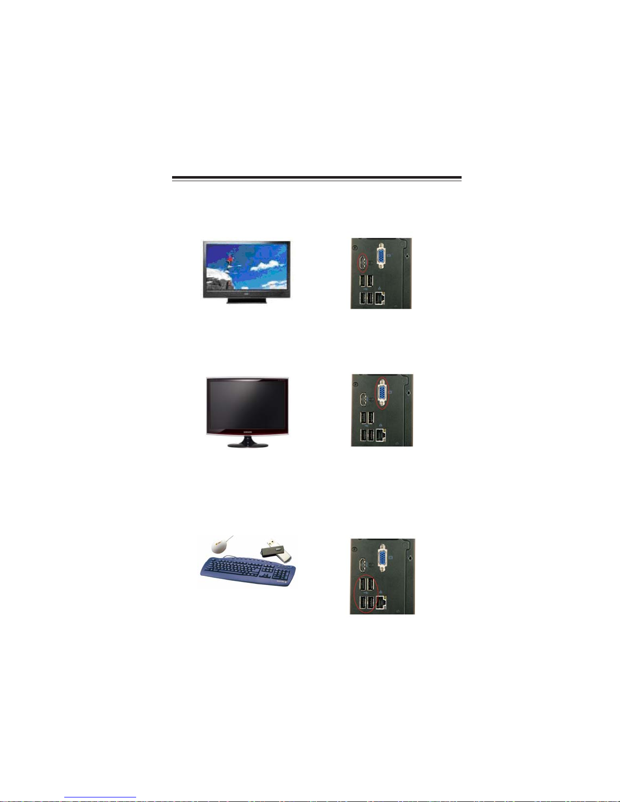
System Quick Installation
1. Connecting HDMI device.
2. Connecting VGA Monitor. (D-SUB Connector)
3. The USB connectors is for attaching USB devices, such as mouse, keyboard,
printer, scanner and other USB-compatible device.
8
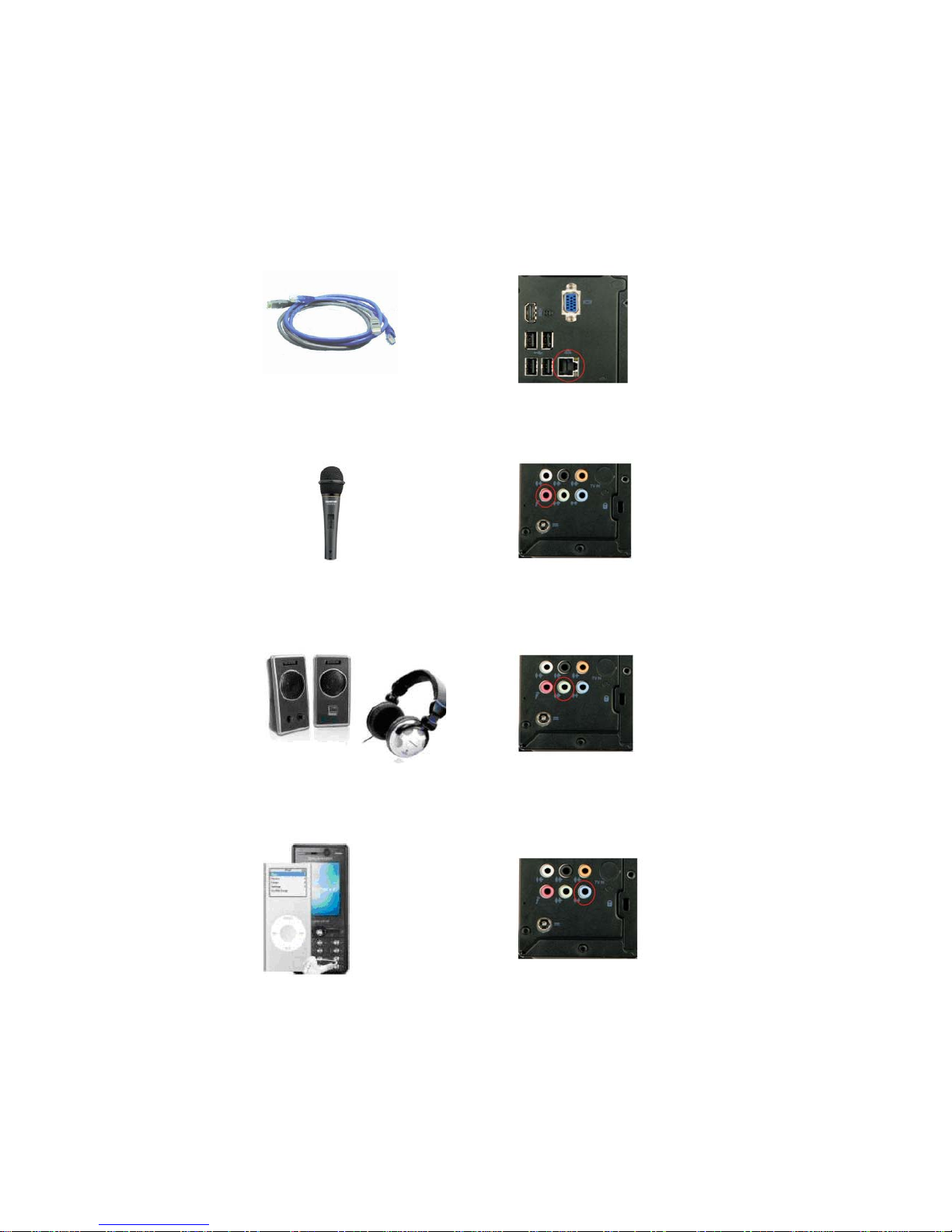
Installing the PC
5. Connecting the Microphone. (Microphone Jack)
4. Connecting the Network. (LAN Connector)
6. Connecting Speakers or Headphones. (Headphone Jack)
7. Connecting External Audio Device. (Line In Jack)
9
Installing the PC
8. Connecting Power. (DC jack)

10
Installing the PC
Memo

11
Using BIOS
AbouttheSetupUtility
The computer uses the latest “American Megatrends Inc. ” BIOS with support for
Windows Plug and Play. The CMOS chip on the motherboard contains the ROM
setup instructions for configuring the motherboard BIOS.
The BIOS (Basic Input and Output System) Setup Utility displays the system’s
configuration status and provides you with options to set system parameters. The
parameters are stored in battery-backed-up CMOS RAM that saves this information
when the power is turned off. When the system is turned back on, the system is
configured with the values you stored in CMOS.
The BIOS Setup Utility enables you to configure:
• Hard drives, diskette drives and peripherals
• Video display type and display options
• Password protection from unauthorized use
• Power Management features
The settings made in the Setup Utility affect how the computer performs. Before
using the Setup Utility, ensure that you understand the Setup Utility options.
This chapter provides explanations for Setup Utility options.
The Standard Configuration
A standard configuration has already been set in the Setup Utility. However, we
recommend that you read this chapter in case you need to make any changes in the
future.
This Setup Utility should be used:
• when changing the system configuration
• when a configuration error is detected and you are prompted to make
changes to the Setup Utility
• when trying to resolve IRQ conflicts
• when making changes to the Power Management configuration
• when changing the password or making other changes to the Security
Setup
Entering the Setup Utility
When you power on the system, BIOS enters the Power-On Self Test (POST)
routines. POST is a series of built-in diagnostics performed by the BIOS. After the
POST routines are completed, the following message appears:
Press DEL to enter SETUP
Chapter 3
Using BIOS
12
Using BIOS
Press the delete key to access the BIOS Setup Utility.
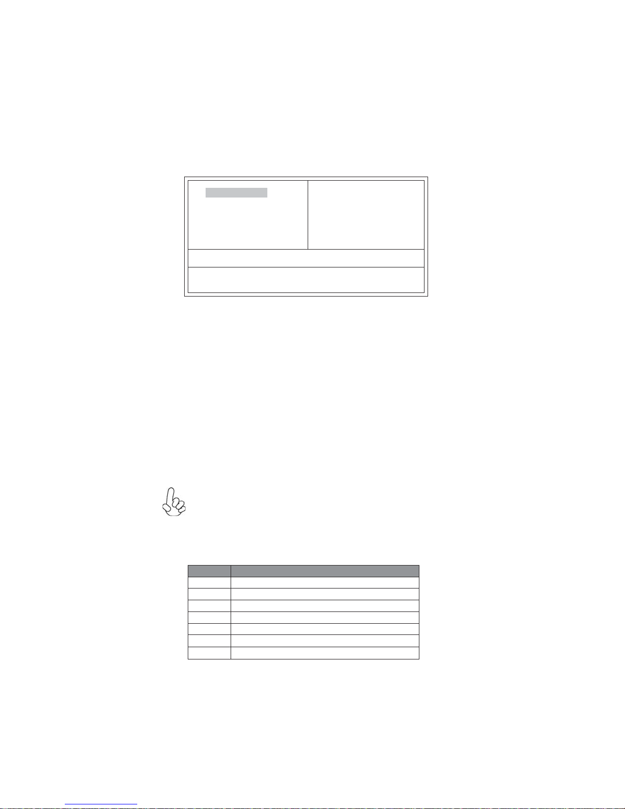
CMOSSetup Utility- Copyright(C)1985-2010,AmericanMegatrends,Inc.
f
f
f
f
Configure TimeandDate.DisplaySystem Information...
v02.67(C)Copyright 1985-2010, AmericanMegatrends,Inc.
f
f
f
StandardCMOS Setup
AdvancedBIOS Features
AdvancedChipset Features
IntegratedPeripherals
PowerManagement Setup
PCHealthStatus
Frequency/VoltageControl
BIOSSecurityFeatures
LoadDefaultSetting
Save& ExitSetup
ExitWithout Saving
f
UsingBIOS
When you start the Setup Utility, the main menu appears. The main menu of the
Setup Utility displays a list of the options that are available. A highlight indicates
which option is currently selected. Use the cursor arrow keys to move the highlight
to other options. When an option is highlighted, execute the option by pressing
<Enter>.
Some options lead to pop-up dialog boxes that prompt you to verify that you wish to
execute that option. Other options lead to dialog boxes that prompt you for infor-
mation.
Some options (marked with a triangle ff
ff
f) lead to submenus that enable you to change
the values for the option. Use the cursor arrow keys to scroll through the items in the
submenu.
In this manual, default values are enclosed in parenthesis. Submenu items are denoted
by a triangle ff
ff
f.
The default BIOS setting for this motherboard apply for most conditions
with optimum performance. We do not suggest users change the default
values in the BIOS setup and take no responsibility to any damage caused
by changing the BIOS settings.
BIOS Navigation Keys
The BIOS navigation keys are listed below:
KEY FUNCTION
Scrolls through the items on a menu
+/- Modifies the selected field’s values
F10 Saves the current configuration and exits setup
F1 Displays a screen that describes all key functions
F9
Loads an optimized setting for better performance
ESC Exits the current menu
mnlk
Enter Select
:Move F10:Save ESC:Exit
+/-/:Value
Enter: Select F9:Optimized Defaults
F1:General Help
mnlk
F7:PreviousValues F8:Fail-SafeDefaults
13
Using BIOS
For the purpose of better product maintenance, we reserve the right to
change the BIOS items presented in the manual. The BIOS setup screens
shown in this chapter are for reference only. Please visit our website for
updated manual.
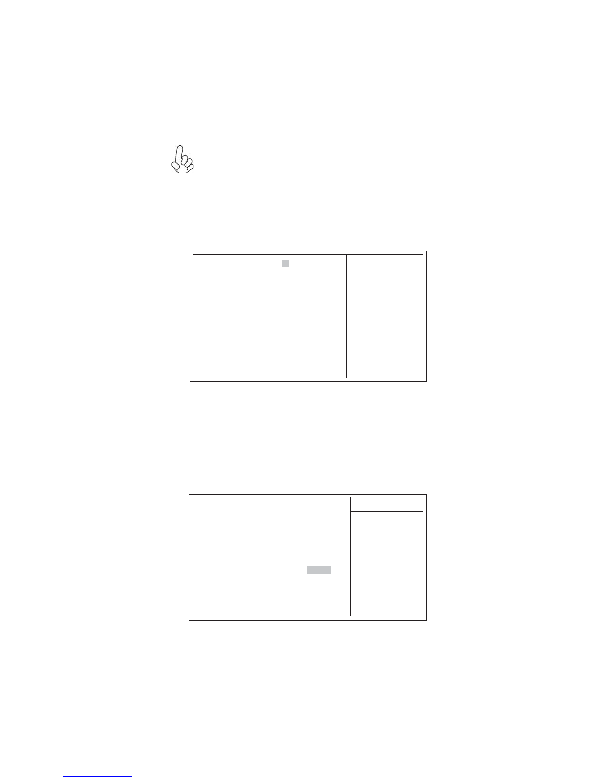
StandardCMOS Setup
This option displays basic information about your system.
HelpItem
CMOSSetup Utility- Copyright(C)1985-2010,AmericanMegatrends,Inc.
Use [ENTER], [TAB]
or [SHIFT-TAB] to
select a field.
Use [+] or [-] to
configuresystemDate.
StandardCMOSSetup
System Date & System Time
The Date and Time items show the current date and time on the computer. If you are
running a Windows OS, these items are automatically updated whenever you make
changes to the Windows Date and Time Properties utility.
f
f
System Date Thu 0101/2009
SystemTime 12 :09:26
SATAPort1 ATAPI CDROM
SATAPort2 Hard Disk
fSATA Port 1~2
This motherboard supports two SATA channels and each channel allows one SATA
device to be installed.
CMOSSetupUtility - Copyright(C)1985-2010, American Megatrends,Inc.
SATAPort1
HelpItem
Selectthe type
ofthe deviceconnected
tothe system.
SATA Port1
Device : ATAPI CDROM
Vendor : Optiarc DVD RW AD-7643S
LBAMode : Supported
PIOMode :4
Async DMA : MultiWord DMA-2
Ultra DMA :Ultra DMA-5
Type Auto
PIOMode Auto
DMA Mode Auto
:Move F10: Save ESC:Exit
+/-/:Value
Enter: Select F9:Optimized Defaults
F1:General Help
mnlk
F7:PreviousValues F8:Fail-SafeDefaults
:Move F10: Save ESC:Exit
+/-/:Value
Enter: Select F9:Optimzed Defaults
F1:General Help
mnlk
F7:PreviousValues F8:Fail-SafeDefaults
Table of contents
Other ECS Desktop manuals


