Brecknell RD65 Specification sheet

RD65 Remote Display
Quick Set-up User Manual
Software Version 13.07.08

Content
1. Specifications ¡¡¡¡¡¡¡¡¡¡¡¡¡¡¡¡¡¡¡¡¡¡¡¡¡¡¡¡1
2. Faceplate ¡¡¡¡¡¡¡.¡¡¡¡¡¡¡¡¡¡¡¡¡¡¡¡¡¡¡¡¡¡¡¡2
3. Communication configuration ¡¡¡¡¡..¡¡¡¡¡¡¡¡¡¡¡¡¡¡¡.. 2
3.1 Details of the 16 protocols ¡ ¡ ¡ ¡ ¡ ¡ ¡ ¡ ..¡ ¡ ¡ ¡ ¡ ¡ ¡ ¡ ¡ ¡ ¡ ¡ ¡ ¡ 2
3.2 RD65 parameters configuration ¡ ¡ ¡ ¡ ¡ ¡ ¡ ¡ ¡ ¡ ¡ ¡ ¡ ¡ ¡ ¡ ¡ .¡ ¡ ¡ .. 7
3.3 Details of RD65 communication interface¡ ¡ ¡ ¡ ¡ ¡ ¡ ¡ ¡ ¡ ¡ ¡ ¡ ¡ ¡ ¡ ¡ 9
3.3.1 RS232 interface ¡ ¡ ¡ ¡ ¡ ¡ ¡ ¡ ¡ ¡ ¡ ¡ ¡ ¡ ¡ ¡ ¡ ¡ ¡ ¡ ¡ ¡ ¡ ¡ ¡ 10
3.3.2 RS485 interface ¡ ¡ ¡ ¡ ¡ ¡ ¡ ¡ ¡ ¡ ¡ ¡ ¡ ¡ ¡ ¡ ¡ ¡ ¡ ¡ ¡ ¡ ¡ ¡ ¡ 10
3.3.3 20mA current loop interface ¡ ¡ ¡ ¡ ¡ ¡ ¡ ¡ ¡ ¡ ¡ ¡ ¡ ¡ ¡ ¡ ¡ ¡ ¡ ¡ 10
4. RD65 installation ¡¡¡¡¡¡¡¡¡¡¡¡¡¡¡¡¡¡¡¡¡¡¡¡¡¡¡..11
4.1 Parts installation ¡ ¡ ¡ ¡ ¡ ¡ ¡ ¡ ¡ ¡ ¡ ¡ ¡ ¡ ¡ ¡ ¡ ¡ ¡ ¡ ¡ ¡ ¡ ¡ ¡ ¡ ¡ . 11
4.2 Installation of suspending way ¡ ¡ ¡ ¡ ¡ ¡ ¡ ¡ ¡ ¡ ¡ ¡ ¡ ¡ ¡ ¡ ¡ ¡ ¡ ¡ ¡ .12
5. The meaning of some displayed symbols¡¡¡¡¡¡¡¡¡¡¡¡¡¡¡.14
6. Trouble shooting ¡¡¡¡¡¡¡¡¡¡¡¡¡¡¡¡¡¡¡¡¡¡¡¡¡¡¡¡14
7. Default factory setting ¡ ¡ ¡ ...............................................................................15
8. Packing list ¡¡¡¡¡..¡¡¡.¡¡¡¡¡¡¡¡¡¡¡¡¡¡¡¡¡¡¡¡¡..15

1
RD65 Remote Display User’s Manual
Thank you for purchasing the RD series remote display. Please read all operating instructions
carefully before use and keep the following points in mind:
* Avoid using in condition of excess variation of line voltage.
* Do not operate near high-power electronic device. These devices emit RF and can cause unstable
readings.
* Ensure the communication data format, protocol, interface selection and setup is correct
before using.
1 Specification:
Model RD65
Communication
interface types
RS232
RS485
20mA current loop (active, self-powered, the host no need to supply
power)
20mA current loop (passive, the host need to supply power)
Data format 8N1, 7E1,7O1 selectable
Baud rate 150bps~19200bps selectable
Protocols 16 Selectable fixed Protocols
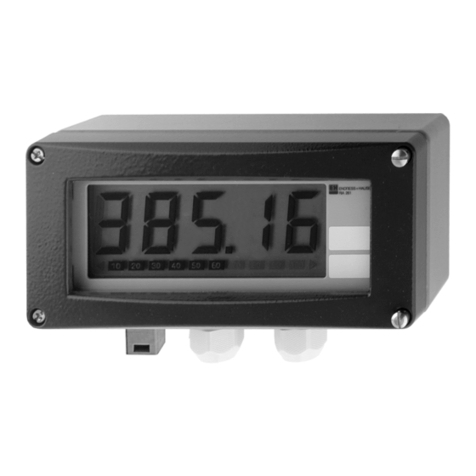
Display content Net /Gross , kg/lb indicators, weight data
Display Type 5”, 7-segment, 6 digits ultra-brightness LED display with
the capacity down to -99,999 and up to 999,999
Operation temperature -20℃ ~ 70℃
Power supply
1) 24VAC 2.0A,AC adaptor。
2) RD65 working current≤1.5A
3) Fuse 2A.
Waterproof grade IP65
Notes: Please b e kindly n oted t hat t he p ower u p v ersion t hat i s d isplayed after t he
count-down is 13.07.08.

2
2. Faceplate
Fig.1
3. Communication configuration
3.1 Details of the 16 Common protocols
3.1.1 Data Format Example: 12345lb Gross; Common GSE Models.
<SP><SP><SP><1><2><3><4><5><6><SP><l><b><SP><SP><SP><SP><G><
r><o><s><s><CR>< LF >
Data Format Example: 12345kg Net
<SP><SP><SP><1><2><3><4><5><SP><k><g><SP><SP><SP><SP><N><e>
<t><SP><SP><CR><LF>
Notes for symbols used in commands and response:
<LF> Line Feed character
<CR> Carriage Return character
Displaying
window
Setting board inside
Power input
Suspension arms
Fuse
RS232/RS485/20mA current loop interface
Light sensor
Fixing screw
Sun-shade

3
<SP> Space
<kg/lb> kg or lb
3.1.2 Data Format Example: 123456lb for Salter/Transcell series Indicators.
<STX><SP><SP><1><2><3><4><5><6><L><G><SP><CR><LF>
Notes for symbols used in commands and response:
<STX> Start of Text
<L/K> LB or KG
<G/N> G = Gross, N = Net
<SP> Space
<CR> Carriage Return character
<LF> Line Feed character
3.1.3 Data Format Example: 123456lb; used with Weigh-Tronix WI125 models.
<SP><G><SP><SP><1><2><3><4><5><6><SP><L><B><SP><CR><LF>
Notes for symbols used in commands and response:
<SP> Space
<G/N> G = Gross, N = Net
<LB/KG> LB or KG
<CR> Carriage Return character
<LF> Line Feed character
3.1.4 Data Format Example: 123456lb; used with Dillon ED Dynamometers.
<SP><1><2><3><4><5><6><SP><l><b><f><CR><LF>
Notes for symbols used in commands and response:
<SP> Space
<LBF/KGF> LB or KG
<CR> Carriage Return character
<LF> Line Feed character

4
3.1.5 Data format example:380.5lb, SBI-140/100, SBI-521 and FI-521 transmit
continuously mode
<SP><SP><SP><SP><3><8><0><.><5><l><b><FF><ETX><LF>
<SP><SP><SP><3><8><0><.><5><l><b><CR><LF>H1H2H3H4<CR><ETX><LF>
<SP><SP><SP><SP><SP><3><8><0><.><5><l><b><CR><LF>H1H2H3<CR><ETX
><LF>
<SP><SP><SP><SP><3><8><0><.><5><l><b><CR><LF>H1H2H3H4<CR><ETX><L
F>
Notes for symbols used in commands and response:
H1H2H3H4:three status bytes, definition refer to EASTHIGH or SBI-140/100 user¡s
manual
<SP> Space (20hex)
<LB/KG> LB=lb, KG=kg
<FF> Form Feed (0chex)
<ETX> end of text. (03hex)
<LF> Line Feed character (0ahex)
3.1.6 Data format example: -9999lb "4 Weight Characters", WI127 transmit data
<SP><G><-><9><9><9><9><SP><l><b><CR><LF>
Notes for symbols used in commands and response:
<SP> Space (20hex)
<G/N> G = Gross, N = Net
<LB/KG> LB=lb, KG=kg
<CR> Carriage Return character (0dhex)
<LF> Line Feed character (0ahex)
3.1.7 Data format example: -100000lb "6 Weight Characters", WI127 transmit data
<SP><G><-><1><0><0><0><0><0><SP><lb><CR><LF>
Notes for symbols used in commands and response:
<SP> Space (20hex)
<G/N> G = Gross, N = Net
<LB/KG> LB=lb, KG=kg
<CR> Carriage Return character (0dhex)

5
<LF> Line Feed character (0ahex)
3.1.8 Data format example: 123123kg, SMA transmit data
<LF><SP><SP><G><SP><SP><-><1><2><3><1><2><3><kg><SP><CR>
Notes for symbols used in commands and response:
<LF> Line Feed character (0ahex)
<SP> Space (20hex)
<G/N> G = Gross, N = Net
<kg/lb> lb = lb, kg = kg
<CR> Carriage Return character (0dhex)
3.1.9 Data format example: 123.233lb, transmit data format of SB-400
<SP><1><2><3><.><2><3><3><lb><G><SP><SP><CR>
Notes for symbols used in commands and response:
<SP> Space (20hex)
<kg/lb>lb = lb,kg = kg
<G/N> G = Gross, N = Net
<CR> Carriage Return character (0dhex)
3.1.10 Data format example: 233233lb, transmit data format of SB-200
<CR><SP><SP><2><3><3><2><3><3><SP><lb><G><ETX>
Notes for symbols used in commands and response:
<CR> Carriage Return character (0dhex)
<SP> Space (20hex)
<kg/lb>lb = lb,kg = kg
<G/N> G = Gross, N = Net
<ETX> end of text. (03hex)
3.1.11 Data format example: 233233lb, transmit data format of IQ355
<STX><SP><SP><2><3><3><2><3><3><L><G><SP><CR><LF>
Notes for symbols used in commands and response:
<STX> Start of Text ( 02hex)
<SP> Space (20hex)
<L/K>L = lb,K = kg
<G/N> G = Gross, N = Net
<CR> Carriage Return character (0dhex)

6
<LF> Line Feed character (0ahex)
3.1.12 Data format example: 233233lb, transmit data format of 205/210
RD65 transmit commands : <ENQ> (05hex, Request weight from the indicator
BI-Directional)
Indicator Response:
<SP><SP><2><3><3><2><3><3><lb><G><SP><SP><CR>
Notes for symbols used in commands and response:
<SP> Space (20hex)
<kg/lb>lb = lb,kg = kg
<G/N> G = Gross, N = Net
<CR> Carriage Return character (0dhex)
3.1.13 Data format example: 323334lb, transmit data format
<STX><y(4)><y(0)><SP><3><2><3><3><3><4><ETX>
Notes for symbols used in commands and response:
<STX> Start of Text (02hex)
<SP> Space (20hex)
<ETX> end of text (03hex)
yy=40 Gross weight (lb), yy=43 Gross weight (kg),
yy=41 net weight (lb), yy=44 net weight ( kg),
yy=42 tare weight ( Lb), yy=45 tare weight (kg)
3.1.14 Data format example: 13233lb, transmit data format of WI-110S/120S
<SP><G><+><1><3><2><3><3><SP><lb><CR><LF>
Notes for symbols used in commands and response:
<SP> Space (20hex)
<G/N> G = Gross, N = Net
<lb/kg>lb = lb,kg = kg
<CR> Carriage Return character (0dhex)
<LF> Line Feed character (0ahex)

7
3.1.15 Data format example: 149946, transmit data format of E1010
<SP><0><0><0><1><4><9><9><4><6><CR>
Notes for symbols used in commands and response:
<SP> Space (20hex)
<CR> Carriage Return character (0dhex)
3.1.16 Data format example: -99999lb "5 Weight Characters", WI127 transmit data
<SP><G><-><9><9><9><9><9><SP><l><b><CR><LF>
Notes for symbols used in commands and response:
<SP> Space (20hex)
<G/N> G = Gross, N = Net
<LB/KG> LB=lb, KG=kg
<CR> Carriage Return character (0dhex)
<LF> Line Feed character (0ahex)
Note: Before communicating between the two devices, please make sure that the setting of
parity, data bits, baud rates along with the RS232 format and communication port is correctly
selected. In normal working mode the RD65 will display the indicated weight from the host.
3.2 RD65 parameters configuration
Fig.2
RD65 configuration summary table:
1 2 3 4 5 6 7 8 9

8
KEY2 (5 DIP switch) KEY3(4 DIP switch) KEY1
(four position switch)
Dip
Position
No. Baud rate
(
bps
)
Dip
Position
No. Data
Format
Dip
Position No.
Host (Indicator
Print Format)
Communication Interface
Type Selection
1
2
3
4 5 6
7
8
9
Position
1 RS232
0
0
0
110 0 0 8N1 0
0
0
0
Format:3.1.1 Position
2 RS485
0
0
1
300 0 1 7O1 0
0
0
1
Format: 3.1.2 Position
3 20mA current
loop
0
1
0
600 1 0 7E1 0
0
1
0
Format: 3.1.3 Position
4
Bluetooth
option if
available
0
1
1
1200 1 1 7E1 0
0
1
1
Format:3.1.4
1
0
0
2400 0
1
0
0
Format:3.1.5
1
0
1
4800 0
1
0
1
Format:3.1.6
1
1
0
9600 0
1
1
0
Format:3.1.75
1
1
1
19200 0
1
1
1
Format:3.1.8
1
0
0
0
Format:3.1.9
1
0
0
1
Format:3.1.10
1
0
1
0
Format:3.1.11
1
0
1
1
Format:3.1.12
1
1
0
0
Format:3.1.13
1
1
0
1
Format:3.1.14
1
1
1
0
Format:3.1.15
1
1
1
1
Format:3.1.16
Note: All the configuration on RD65 must be done in the power off condition !

9
3.3 Details of RD65 communication interface
Host
Wires
RD65
ABC
D
12
3 4
56
78
9
1
2
4
65
3
9
78
1
2
3
4
5
6
7
8
9
1
2
3
4
5
6
7
8
9
ABCD
Fig.3 Connection between RD65 and Host
A ---- 9 pin socket(pin) on RD65
B ---- 9 pin plug (hole) on one end of connected wire
C ---- DB9 plug (pin) on another end of connected wire
The Color of wires on B and C interface cable:
Connector “B” Pin# Color Connector “C” Pin#
1 ------------ Red ------------ 1
2 ------------ Black ------------ 2
3 ------------ Yellow ------------ 3
4 ------------ Green ------------ 4
5 ------------ Blue ------------ 5
6 ------------ White ------------ 6
7-9 ----------- not used ------------ 7-9

10
The Color of wires on internal PCB to Connector A:
Connector “A” Pin# Wires Color
1 ------------ Brown
2 ------------ Red
3 ------------ Orange
4 ------------ Yellow
5 ------------ Green
6 ------------ Blue
3.3.1 RS232 Interface connection
Connector “C” Pin# Function Color
2 ------------ RXD Black
3 ------------ TXD Yellow
5 ------------- RD_AGND Blue
3.3.2 RS485 interface connection
Connector “C” Pin# Function Color
1 ------------ RS485 receive + Red
2 ------------ RS485 receive - Black
3 ------------ RS485 transmit + Yellow
4 ------------ RS485 transmit - Green
5 ------------- RD_AGND Blue
3.3.3 20mA current loop interface connection
Connector “C” Pin# Function Color
1 ------------ 20mA Current Loop Transmit + Red
2 ------------ 20mA Current Loop Transmit - Black
3 ------------ 20mA Current Loop Receive + Yellow
4 ------------ 20mA Current Loop Receive - Green
5 ------------ RD_AGND Blue
6 ------------ RD_Vout White
The color definition of connecting wire between setting board and 9 pins B connector plugs
on RD65:
PIN NUMBER COLOR
① ------------ RED
② ------------- ORANGE

11
③ ------------- YELLOW
④ ------------- GREEN
⑤ ------------- BLUE
⑥ ------------- PURPLE
4 RD65 installation
4.1 Parts installation:
4.1.1 Hanging rings installation
Fig.8
Parts name:
1、Remote display
2、Sun-shade
3、M12 nut
4、Hanging rings
5、Suspension arms
6、Lock nut

12
Steps:
1 :Loosen the lock nut (6) by M12 spanner;
2 :Turn around the suspension arms to a proper position;
3 :Put the hanging-rings(4) into the hole, screw M12 nut (3) onto the hanging-rings(4);
4 :Adjust the suspension arms (5) to a proper angle and fasten the lock nut(6).
4.1.2 Adjust Sun-shade
Fig.9
Parts name:
1、Remote display
2、Sun-shade
6、Lock nut
7、Sun-shade turn axis
Steps:
1 :Loosen the lock nut by M12 spanner;
2 :Turn around the suspension arms to a proper position;
3 :Adjust sun-shade to a proper angle;
4 :Fasten the lock nut.

13
4.2 Installation of suspending way
4.2.1 Install the remote display through a suspender or suspended wire
1) Put a suspender into the rings or put a burly wire through the rings to hang the remote
display; and be careful not to drop the Remote Display.
2) Loosen the locknut, adjust the display window angle and fasten the locknut, and be
careful: don¡t let the lock nut be removed fully during the installation
Fig.10
4.2.2 Install the remote display onto the wall
1) Push two expansion bolts into the wall
2) Screw self tapping screws into expansion bolts and keep 5mm to 8mm out of the wall.
3) Loosen the locknut, move away two hanging-rings, hang the remote display onto self
tapping screws; adjust the display window angle and fasten the locknut.
4) Be careful: don’t let the lock nut be removed fully during the installation
Suspender
Remote Display
Lock nut
Hanging-rings

14
Fig.11
5 The meaning of some displayed symbols:
1) Err01:no communication
2) Err02:incorrect format data received.
3) Err03: over displaying range
4) ¯¯¯¯¯ :over range
5) ______:below range
6 Trouble shooting
Problem Possible cause Check
No display 1)fuse damaged
2)adaptor damaged
Replace fuse or adaptor
Display too dark 1) Low voltage
2) Inner part damaged
Check the input voltage and
replace the damaged part or
main PCB
Err01
(no communication)
1) RD65 data format is different from the host
2) Communication cable is not connected
correctly.
Check cable and the data
format setup
Err02
( in-
correct format
data received)
1)Format switch is not set correctly.
2)Host is not set correctly.
3)unknown host or data format used on host
device
Check whether the protocol
is matched between RD65
and Host.
Remote Display
Lock nut
expansion bolt
expansion bolt
Suspension arms

15
7 Default factory setting
KEY 1 RS232 position
KEY 2
(1.2.3)
“110”--- 9600bps baud rate
KEY 2
(4.5)
“00”---“8N1”:8 data bits, no parity bit,1 stop bit
KEY3
(6.7.8.9)
“0000”--- format 3.1.1 indicator’s protocol used
8 Packing list:
Parts name Quantity
AC230V/AC24V 2.0A UL waterproof adaptor 1
RS232 10m cable 1
User’s manual 1
Hex Wrench 1
2A fuse 3
RD65 Remote Display 1
Service Parts Available Quantity
AC110V/AC24V 2.0A UL waterproof adaptor with
Main pc board
1
AWT05-504388
USA UK and Europe
Brecknell Brecknell
1000 Armstrong Drive Foundry Lane
Fairmont MN 56031 Smethwick,
Toll Free: 800-637-0529 West Midlands, B66 2LP.
Tel: 507-238-8702 Tel: +44 (0) 845 246 6717
Fax: 507-238-8271 Fax: +44 (0) 845 246 6718
Email:sales@brecknellscales.com Email: sales@brecknellscales.co.uk
www. brecknellscales.com Web site: www. brecknellscales.co.uk
Other manuals for RD65
1
Table of contents
Other Brecknell Monitor manuals


