Brenell Mark 5 Series 2 User manual

OPERATING
INSTRUCTIONS
forthe
Brenell
Mark
5
Series
2
TAPE
RECORDER
IMPORTANT
Before
attempting
to
operate this
instrument,
be
sure
to
study careful
these
instructions.
In the
event
of
damage
to the
Recorder through
wrong connection
or
other misuse,
the
manufacturers
can
accept
no
responsibility.
Price:
Five
shillings
GENERAL
DESCRIPTION
includingrecording
and
playback
sequences,
together
with:
Hints
for
improving
recordings
............
Page
8
Incorporating
into
a
Hi-Fiinstallation
.........
Page
II
Maintenance
Page
14
Specification
Page
20
Glossary
Page
22
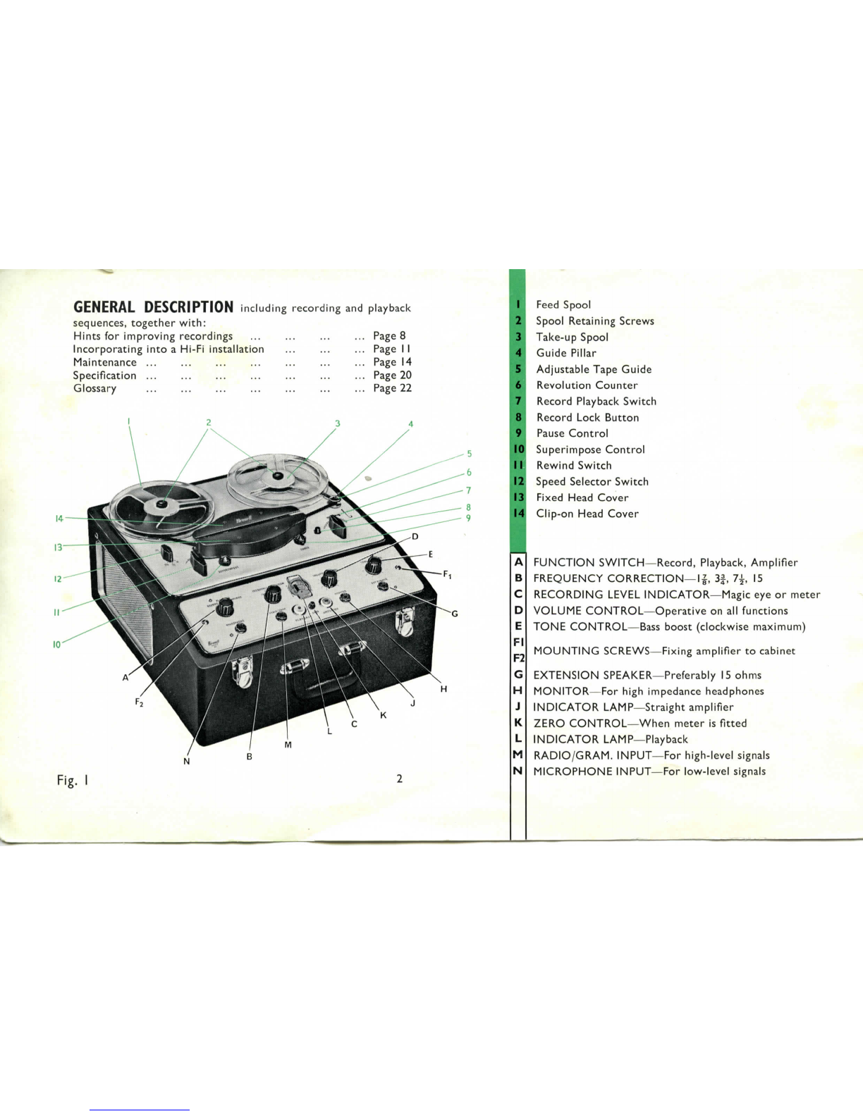
Fig.
I
Feed
Spool
Spool
Retaining
Screws
Take-upSpool
Guide
Pillar
Adjustable
TapeGuide
Revolution
Counter
Record
PlaybackSwitch
Record
Lock
Button
Pause
Control
Superimpose
Control
RewindSwitch
Speed
SelectorSwitch
Fixed
HeadCover
Clip-on
HeadCover
FUNCTION
SWITCH—Record,
Playback,
Amplifier
FREQUENCY
CORRECTION—IJ,
3|,
7f
15
RECORDING
LEVEL
INDICATOR—Magic
eyeor
meter
VOLUME
CONTROL—Operative
onall
functions
TONE
CONTROL—Bass
boost(clockwisemaximum)
MOUNTING
SCREWS—Fixing
amplifier
to
cabinet
EXTENSION
SPEAKER—Preferably
IS
ohms
MONITOR—For
highimpedance
headphones
INDICATOR
LAMP—Straight
amplifier
ZERO
CONTROL—When
meter
is
fitted
INDICATOR
LAMP—Playback
RADIO/GRAM.
INPUT—For
high-levelsignals
MICROPHONE
INPUT—For
low-level
signals

MAINS
CABLE
This
isa
three-cored
cable
which
is
stored
inthe
left-handrear
compartment(viewed
from
the
rear).
Choose
a
suitablethree-pin
mains
plug
and
connect
the
greenlead
tothe
earth
pin
(largest)
andthetwo
remaining
leads
tothe
smaller
pins.
If a
two-pin
plugmust
be
used,
the
green(earth)leadmust
be
leftdisconnected
and
suitablyinsulated.
MAINS
ADJUSTMENT
PLUG
This
is
situated
within
right-handrearcompartment
and
contains
the
mains
fuse
which
is
easily
renewed.
Ensure
that
the
plug
issettothe
correctvoltageposition
for
your
electricitysupply.
i.e.,
240V
for
mains
of
220V
to
250V
210
V for
mains
of200V to220V
*IIOVfor
mains
of
100
V
to
125V
(thepowerconsumption
is
approx.
100
watts).
*Use
ONLY
onthe
special model
fitted
with
117
V
motors
and
suitable
ONLY
for use on
100-125
V
A.C.
supplies.
DO NOT
operate
the
special model
on
higher
voltage
mains
supplies unless
a
suitable
step-
down
transformer
is
used.
A
converter
to
enable
the
machine
tobe
operated
from
D.C.mains
or a car
battery
can be
obtained
from
yourdealer.
The
mains
switch
is
mounted
on
thispanel
and
will
switchpower
to
both
deck
and
amplifiers.
Also
mounted
onthe
mainsadjust-
mentpanel
isa
device
known
asa
"
Humdinger."
This
control
is
preset
atthe
factory
and
further
information
onitmaybe
found
in
the
Glossary.
LOADING
THE
TAPE
Before
loading
the
tape
forthe
first
time,
remove
the
headcovers
in
order
to
familiarise
yourself
with
the
position
ofthe
components,
the
working
ofthe
pressure
pads
and
pinchwheel.
The
upper
half
of
headcover
isa
pressed
fit,
and
needs
only
tobe
lifted
from
its
retainingposts;
the
lowerhalf
is
held
in
position
bytwo
screws.
To
loadtape,
place
full
reel
on
left-handspindle
and
thread
as
shown
onthe
diagram(Fig.
2).
With
the
tapecorrectlythreaded,
give
the
deck
a
trial
run
preparatory
to
making
a
recording,thus
familiarising
yourself
with
the
switchingoperations.
When
the
right-handswitch
onthe
deck
is
operated(record/play-
back)
the
tape
will
be
transported
from
left
to
right
across
the
erase
and
record/playback
heads
ata
speed
dependent
onthe
size
of
capstan
sleeve
inuseandthe
setting
ofthe
speed
switch.
The
left-handknob
isfor
rewinding
or
winding
onthe
tape
at
high
speed,
and
will
onlyoperate
ifthe
record/playbackswitch
isinits
STOP
position.

Al,
A2,A3
Tapeguides
B
Erase
head
C
Tapecontactrelease
pin
Dl
Retainingposts
for
upperhalfheadcover
D2
Retainingposts
for
lower
halfheadcover
E
Record/playbackhead
F
Azimuth
adjustmentscrew
G
Capstanshaft
H
Capstansleeve
J
Adjustabletapeguide
AlC B
K
Pinchwheel
LI,L2
Pressure
Pads
M
Take-up
pin
N
Pressure
pad
operating
lever
O
Crescent-shapedlever
P
Pause
control
R
Superimpose
control
S
Pressure
pad
spring
V
-jV'
freemovement
W
Supplementaryguide
pillar
Fig.
2.
Head
layout
and
tape
lacing
diagram
SPOOL
RETAINING
SCREWS
Screws
are
supplied
for
retaining
the
tapespools
onthe
hubs.
Whilst
itisnot
essential
to
fit
these
screws
whenrecording,
or
replaying
the
tape,theyshould
be
used
whentransporting
the
machine
in
order
to
hold
the
spools
in
position.
Should
the
screws
be
omitted
duringfastwind
or
re-wind,
itis
inevitable
that
a
certainamount
of
vibration
ofthe
spool
will
occur.
Adjustable
tape
guide
In
order
to
enable
spools
of
variedtypes
tobe
used
without
the
edge
ofthe
spool
fouling
the
tape,
an
adjustableguide
is
fitted.
Adjust
as
required
by
releasing
the
lower
milled
circular
nutand
raising
or
lowering
the
guide
by
rotating
the
upper
portion.
Finally,
ensure
that
the
lower
lockingscrew
is
re-tightened.
Speed-changeswitch
This
three-position
switch
gives
speeds
of:
(a)
with
largediameter
capstan
sleeve—IS,
7^,
3£
i.p.s.
(b)
with
smalldiameter
capstan
sleeve—7^-,
3£,
If
i.p.s.
Thisswitch
does
not
rotate
through
360°.
The
figures
above
the
switch
areforuse
with
the
smaller
sleeve
andthe
lower
with
the
larger
sleeve.
The
machine
is
supplied
with
the
large
capstan
sleeve
in
position
and
the
smallcapstansleeve
fitted
toW the
supplementaryguide
pillar.
The
sleeves
are
retained
onthe
capstan
shaft
with
grub
screws.
Ensure
screw
is
tight,
or
speed
fluctuations
will
occur.
(NOTE:
The
capstan
sleeve
should
be
fixed
with
the
grubscrewnear
the
deck
plate,allowing
£"
clearancebetween
endof
sleeve
and
deckplate.)
RECORDING
SEQUENCE
1
After
ascertaining
that
the
mainsadjustmentplug
atthe
rear
of
the
machine
is
correctly
setto
suityour
mains
voltage,
connect
the
machine
tothe
mains
supply
and
switch
on
(recorder
mains
switch
isonthe
same
panel
ofthe
power
unit
as
the
mains
adjustmentplug).
2Fit
reel
of
tape
to
left-hand(feed)spoolholder
and
lace
the
tape
asper
diagram(Fig.
2)tothe
emptytake-upspool
(right-
hand),ensuring
that
the
"
sensitive
"
side
ofthe
tape
faces
the
heads.
(Most
tapes
have
a
"
glossy
"
side
anda
"
dull
"
side—
itisthe
"
dull
"-side
which
is
coated
with
iron
oxide
andisthe
sensitive
side).
3
Select
recording
speed
and
adjust
the
frequencycorrection
switch
(B,
Fig.
I) to
match. (Thefaster
the
tape
speed
the

better
the
recordingquality.
If
quality
isnotso
important,
then
a
lower
speed
maybe
used
to
allowlongerrecording
periods
per
tape.)
4
Insertmicrophone
jack
plug
into
microphone
input
socket
or,
if
recording
from
radio,couple
the
radio
tothe
radio/gram
socket.
(See
special
noteregardinggramophonepick-ups
in
"
Hints
for
ImprovingRecording
"
section.)
5
Switchamplifier
to
record
and
adjust
the
volume
control
until
the
loudest(peak)signal
from
radio
or
microphone
causes
the
magic
eye
bars
to
justmeet
or,ifa
meter
is
fitted
in
lieu
ofeye
(seenote
on
zeroingmeter
inthe
Glossary—
"
Modulation
Level
Indicator
")
until
the
needle
rises
to
"
7
"
on
the
dial(i.e.
tothe
left-handedge
ofthered
portion
ofthe
scale).
6
Note
the
position
ofthe
volume
control
and
then
turn
it
fully
anti-clockwise
to
minimum.
7Now
depress
the
button
near
the
deckrecord/playback
switch
and
turn
thisswitch
tothe
"
Record
"
position.
8
Advance
the
volume
control
to
positionnoted
in6and
record-
ing
will
takeplace.
Ifthe
superimpose
control
is
inoperative,i.e.
itissetto
allow
the
erase
pressure
padto
press
the
tape
tothe
erase
head,
any
signals
which
have
beenpreviouslyrecorded
will
be
erased.
(See
note
on
"
Superimposing
"
inthe
Glossary.)
10
Onemay
hear
the
signalbeingrecorded
on
headphonescon-
nected
tothe
monitor
socket.
11
Asthe
recordingproceeds,
onemay
omit
certainitems,
for
example,
announcementsbetween
musical
items
ina
broad-
cast,
by
temporarilyhalting
the
tapemovement
by
operating
the
pause
control.
(Fade
outthe
signal
by
turning
down
the
volume
control—operate
pause
control
and
afterreleasing
this
control
forthe
continuance
ofthe
recording,
advance
the
volume
control
toits
originalsetting.)
12
To
stop
the
machine,
switch
rhe
deckrecord/playbackswitch
to
the
central
"
stop
"
position.
13
When
the
whole
ofthe
tape
has
passed
tothe
take-upspool,
thisreel
maybe
inverted
and
transferred
tothe
feed
side
in
order
that
a
further
recording
maybe
made.
(Seenote
on
"
Twin
Track
"
inthe
Glossary.)

PLAYBACK
SEQUENCE
1
Once
a
recording
has
beenmade
itmaybe
replayed
any
number
of
times
until
you
decide
to
erase
it.
(Erasure
is
auto-
maticallyaccomplishedwhen
another
recording
is
made
unless
superimposing
isin
operation.)
2
Place
the
recordedtape
onthe
feedspool
(orifyou
havejust
finished
a
recording
session,
rewind
the
tape
ontothe
feed
spool)
and
lace
itto
take-upspoolexactly
asfor
recording
purposes.
3
Switchamplifier
to
playback(playback
indicator
will
light).
Turn
volume
control
to
minimum.
Select
speed
of
deck
to
coincide
with
recording
speed
and
similarly
set
frequency
correction
switch.
4
Turn
the
deckrecord/playbackswitch
to
playback.Advance
volume
control
and
adjust
tone
control
as
required.
(The
frequency
correction
switch
maybe
adjusted
toany
position
desired
buta
"
flat
"
response
will
be
obtainedwhen
itisset
tothe
positioncoinciding
with
the
deckspeed.)
5
Shouldplayback
be
required
onan
external
speaker,simply
plug
the
externalspeaker
into
the
appropriate
socket
ofthe
amplifier.
(Internal
speaker
will
be
automaticallydis-
connected.)
6An
external
amplifier
maybe
used
with
the
recorder
by
con-
necting
itto
either
the(a)
monitor
socket
and
adjusting
the
recordervolume
control
tothe
requiredlevel,
(b)
co-axial
socket
onthe
amplifier
chassis.
The
signal
at
this
socket
is
not
governed
bythe
recordervolume
control.
(Normally
this
socket
is
used
with
externalhigh
fidelity
pre-amplifiers
and
amplifiers
andis
situated
atthe
rear
to
enableunobtrusive
connection
tobe
madewhen
the
recordingamplifier
isin-
stalled
ina
"
permanent
"
hi-fi
installation.)
Ifitis
desired
to
mute
the
internal
loudspeaker
when
operating
as(a)
above,
insert
a
jack-plug
which
hasa
15
ohm
resistor
wired
across
it
into
the
external
speaker
socket.
WARNING—Do
not
mute
with
an
open-circuited
jack-plug
or
damage
will
be
caused
tothe
amplifier.
STRAIGHTAMPLIFIER
If
the
function
switch
is
turned
to
"
Amplifier
"
the
amplifier
only
will
be
available
for
reproducingsignals
from
radio
tuner,
pick-ups
and
microphones.
It
should
be
noted
that
when
a
microphone
is
used
in
close
proximity
toa
loudspeaker,
"
acousticfeed-back
"
(howling)
will
occur—therefore
alwaysensure
that
the
micro-
phone
and
speaker
area
considerabledistance
apart.
Hints
for
improving
recordings
MICROPHONES
Seldom
isanyone
type
of
microphone
suitable
for
every
circum-
stance
andwe
recommendthey
be
used
as
follows:
Ribbon:
For
highquality
"
live
"
musical
recording
(indoors).
Dynamic
(moving
coil)—For
indoor
and
outdoor
use:
speech,
music,etc.
Crystal—Principally
for
speech
recordings.
RECORDING
FROM
MICROPHONE
Avoidplacing
the
microphonenear
the
motor
ofthe
taperecorder.
Wedonot
recommend
that
the
microphone
be
placed
onthe
same
table
asthe
tape
recorder
whenrecording.Earth
the
machine
ifthe
microphone
is
used
with
a
longercablethan
that
supplied.
This
will
avoid
excessive
A.C.
hum.Only
use
screened
extension
cables
(co-axialcable
as
used
forTV
aerial
leads
is
suit-
able).Alwaysensure
that
microphonecable
is
correctly
connected
tothe
jack
plug—broken
leads
or
reversedconnections
will
give
loud
hum.
Ifa low
impedancemicrophone
is
used
a
matching
transformer
will
be
required.
Donotrubthe
hand
or
fingers
onthe
case
ofa
microphonewhilst
recordingotherwise
"
noise
"
will
be
recorded.
Endeavour
to
persuade
people
to
speak
oneata
time
andnotasa
group
because
a
microphonerecords
allit
"
hears
"
and
cannot
discriminate
ascanthe
humanear.
RECORDING
FROM
RADIO
The
bestrecordings
will
be
obtained
from
FM-VHFtransmissions.
Donot
record
from
a
radioreceiver
by
means
ofa
microphone
if
one
ofthe
following
methods
canbe
employed:
(a)
Record
from
extensionspeakersocketofradioreceiver.
(b)
Record
from
the
diode
output
ofthe
radio
receiver.Your
radio
may
requiremodification
ifno
diode
output
socket
is
fitted.
Your
localdealer
can
advise
you.
Always
use
screenedcable
to
coupleradio
to
tape
recorder.
Always
consultyourdealerbeforeusing
an
A.C./D.C.
radio
orTV
receiver
which
hasno
extensionspeakersocket.
The
recording
signal
source
may
requiremodification
to
enable
the
receiver
tobe
used
without
risk
of
electricshock.

Always
ensure
that
any
plugs
or
connections
are
secure
otherwise
intermittent
crackling
maybe
produced.
PAUSE
CONTROL
Immediately
prior
to
using
the
pause
control,
turn
down
the
volume
control.
Conversely,
revert
to
normalvolume
as
soon
as
pause
control
is
released.
A
little
practice
will
soon
enable
the
user
to
makerecordings
of
excellentquality
ata
uniformsound
level
with
all
unwantedmaterial
omitted.
CARE
OF
HEADS
AND
GUIDES
Any
accumulation
of
dirt
or
oxideparticles
from
the
tape
will
preventgoodrecordingsbeingmade.Periodically,therefore,
clean
the
working
surfaces
of
both
heads
with
methylatedspirit
applied
with
a
small
camel
hairbrush.Take
special
care
notto
scratch
the
surfaces
ofthe
heads.
The
tapeguides
and
capstan
shouldalso
be
periodicallycleaned
with
methylatedspirits
to
removeoxidedeposit.
Access
to
heads
and
tapeguides
is
available
merely
by
removing
the
mouldedcovers.
SELECTING
AN
EXTENSION
LOUDSPEAKER
The
choice
ofa
loudspeaker
isa
verypersonal
thing,
andwe
suggest
that
the
listenershouldendeavour
to
hear
a
variety
of
makes
(within
his
pricerange),
inuse
with
the
taperecorder.
Ifthe
speakers
canbe
heard
within
the
listener's
own
home,
so
much
the
better,
as
roomacousticsmust
be
taken
into
account.
RECORDING
FROM
GRAMOPHONE
PICKUP
It
should
be
borne
in
mind
that
moderngramophone
discs
are
deliberatelyrecorded
with
an
attenuated(reduced)
bass
response
and
an
accentuatedtreble
response
compared
with
the
original
sound.
Therefore,
if
satisfactorytaperecordings
aretobe
made,suitable
frequency
compensationmust
be
incorporatedbetween
the
gramophonepick-up
andthe
taperecordingamplifier
to
reverse
the
disc's
recordingcharacteristics.
Such
frequencycompensationcircuits
are
incorporated
in
high
fidelity
pre-amplifiers
and
thosepeople
possessing
such
equipment
should
record
from
gramophone
discs
onlyafter
the
signal
has
passed
through
their
hi-fi
pre-amplifiers.
PICKUPS
Disc
recordings
from
domesticradiogramsshould
be
taken
from
the
extension
speaker
sockets
ofthe
radiogram
in
order
to
take
advantage
ofany
frequencycorrectioncircuitsincorporated
therein.
Shouldyourradiogram
or
recordplayer
NOT
have
extension
speaker
sockets,
donot
attempt
touseitin
conjunction

with
your
tape
recorder
before
consulting
a
qualified
electrician
or
dealer.Many
record
players
are
dangerous
touse
unless
fitted
with
isolatingtransformers
to
preventelectricalshocks.
Mostmanufacturers
of
gramophonepick-ups
will
supply,
on
request,details
of
frequency
correction
circuits
foruse
with
their
products—and
to
avoid
any
misunderstanding,
one
should
quote
the
sensitivities
and
impedances
ofthe
amplifier
with
which
a
pick-up
istobe
used
whenapplying
for
information.
Inthe
case
ofthe
BrenellMark
5
Series
2,
quote:
"
2
mV
into
I
megohm
"
and
"
80mV
into
220k
ohms."
Please
note
that
permissionmust
be
obtained
from
the
gramo-
phonerecordmanufacturerbeforetaperecordings
are
made
from
discs.
Failure
to
obtain
permission
isa
breach
of
copyright.
-~T
-
~
~
When
stopping
the
tape,
the
re-wind
switch
must
be
brought
quickly
tothe
central
position
in
order
to
allow
instantaneous
action
by
both
brakes.
(An
alternative method
isto
switch—very
quickly
indeed—from
the
re-wind
to the
wind position
(or
vice
versa), thus
transferring
the
power from
one
motor
to
the
other
and
achieving
a
gradual
slowing
down
of the
tape,
then,
just
as the
tape
movement
is
about
to
change,
turn
the
sw'tch
to the
central
'stop'
position. This
method requires a little practice but is
mentioned
at the
request
of
a.number
of
people, who, having learned
to use
it,
prefer
it to the
abrupt arresting
of
the
tape
movement.)
Fig.
3
POWER
SUPPLY
COMPENSATED
LOW-LEVEL
OUTPUT
SOCKET
10
Incorporating
the
Mark
5
Series
2
Recorder
into
a
permanent
Hi-Fi
installation
The
Mark
5
Series
2
taperecorder
is
oftensold
inthe
threemain
units:
tapedeck
amplifier
power
unit
foruse
with,
andfor
installation
into,
a
high
fidelity
console.
As
all
three
units
are
coupledtogether
by
means
of
non-reversible
plugs
and
sockets
(no
solderingrequired)
the
addition
of
tape
recording
facilities
to
exisingequipment
is
greatlysimplified.
DECK
MOUNTING
(Masksize
isfx
12
)
The
tapedeckshould
be
mounted
HORIZONTALLY
for
best
results.
An
aperture
of
I4"x
10^"
ina
mountingboard
will
allow
the
deck
to
"
drop
through
"
until
the
deckplaterests
onthe
board.
Rubbergrommets
or
other
rubbercushioningshould
be
fitted
between
the
deckplate
andthe
mountingboard.
(Beforeactuallymounting,remove
the
mask
from
the
deck
to
gain
access
tothe
four
holes
for
fixingpurposes.)
The
deckshould
be
mountedapproximately
£•"
clear
ofthe
board
to
facilitateventilation.Clearancebelow
the
deckplatemust
beat
least
5".
8^"
reels
of
tape
will
overlap
the
deckplate
IJ"
tothe
rear
and
Ij"
on
both
sides.
AMPLIFIER
MOUNTING
(Masksize
151
x41)
An
aperture
I2j"x4"
will
enable
the
amplifier
to
"
drop
through
"
a
mounting
board
until
the
maskrests
onthe
board.
Fixing
isby
means
oftwo
screws
through
the
mask.
The
amplifier
maybe
mounted
atany
angle.
POWER
UNIT
MOUNTING
The
power
unit
is
separate
from
the
amplifier
in
order
that
itmay
be
sited
to
induce
the
minimum
A.C.
hum
into
the
heads
andthe
II
amplifier.Therefore,aftermounting
the
deck
and
amplifier,
the
three
units
will
be
coupled
together,
a
loudspeakerattached
and
the
power
unit
movedaround
until
the
position
for
minimum
hum
is
found.(See
note
on
"
Hum.")
Fixing
is
thenaccomplished
by
means
of
screws
through
the
holesprovided.
HUM
It
should
be
noted
that
hummaybe
introduced
from:
a
mains
transformer
"
earth
"
loops
and
thereforecertainprecautionsmust
be
taken
and
experiments
made
should
excessive
humbe
encountered.
Hum
from
mainstransformers
maybe
introduced
into:
the
tape
heads
the
recording/playbackamplifier
the
cables
from
heads
to
amplifier
the
cables
carrying
the
signals
toand
from
the
amplifiers.
The
Mark
5
Series
2
power
unit
hasa
special
low
A.C.radiation
mains
transformer.
Beforescrewing
the
unit
into
a
permanent
position
the
deck,amplifier
and
power
unit
should
be
coupled
together
(deck
and
amplifier
in
permanentpositions),
anda
loud-
speaker
plugged
into
the
amplifier.
Now
connect
the
equipment
tothe
mains
supply,switch
the
amplifier
to
playback
andsetthe
volume
and
tone
controls
to
maximum.
Adjust
the
humdinger
onthe
power
unit
for
minimum
hum—if
no
definite
position
canbe
ascertained,
setit
mid-way.Move
the
power
unit
(beingcareful
notto
touch
any
components
ora
shock
may
be
received)
toa
position
in
which
the
minimum
humis
heard
from
the
loudspeaker,thenscrew
the
power
unit
down
in
this
position.
(If
thisposition
is
inconvenient
forthe
operation
ofthe
mains
switch,
putthe
switch
tothe
"
ON
"
position
and
instal
anotherswitch
ina
moreconvenientposition,
such
asonthe
deck
mounting
board.)
Now
switch
onthe
mainamplifyingequipment
you
will
be
using
with
the
taperecordingequipment
and
listen
forhuminthe
speaker
connected
tothe
playback
amplifier.
Should
thehum
level
rise
with
the
switching
onofthe
mainamplifyingequipment,
it
will
be
necessary
to
move
the
unit
in
which
the
mainstransformer
is
situated
(or
move
the
tapedeckand/or
amplifier).
COUPLINGAMPLIFIER
TO
HI-FI
EQUIPMENT
The
co-axialsocket
onthe
rear
ofthe
Brenellamplifiershould
be
coupled
tothe
appropriate
input
socket
ofthe
hi-fi
pre-amplifier
using
goodqualityco-axialcable.
It
should
be
noted
that
the
signal
from
the
co-axialsocket
is
frequency
corrected
and
must
notbefed
into
a
"
tape
input
"
socket
inthe
hi-fi
pre-amplifierwhich
is
designed
for
direct
connec-
tion
to
a
tape
head.
Ifthe
onlysocketmarked
"
tape
"
is
unsuitable,
12
couple
tothe
"
extra
"
or
"
auxiliary
"
socketdesigned
to
receive
a
"
flat
"
or
compensatedsignal.
Should
the
strength
ofthe
signal
from
the
Mark
5
amplifier
betoo
high
and
there
isnota
presetgain
control
incorporated
inthe
hi-fi
pre-amplifier,
the
signal
must
befedviaa
screened
volumecontrol
(value
50k to
100
k
ohms)
or
attenuator.
(a)
To
Record
Follow
the
earlierinstructions
on
thissubject
in
thisbooklet,
bearing
in
mind
that
a
signal
for
recordingpurposes
maybe
obtained
from
either
the
loudspeaker
output
ofthe
hi-fi
amplifier
or
from
the
"record"
socket
ofthe
hi-fi
pre-amplifier
(most
pre-amplifiers
have
thisprovision).Microphones
will
be
plugged
directly
into
the
recordingamplifier.
(b)
To
Replay
Tape
recordings
maybe
replayed
via
hi-fi
amplifyingequipment
by
connectingeither
(a)the
co-axialsocket
or (b) the
monitor
socket
onthe
Mark
5
Series
2
amplifier
tothe
hi-fi
pre-
amplifier,
ifthe
outputfrom
(a)is
insufficient.
Output
level
of(b)
will
dependupon
the
adjustment
ofthe
playback
amplifier'svolume
control.
EARTH
LOOPS
Hum may be
introduced
into
amplifyingequipment
by
having
too
many
earthpotentiallinking
cables
anditis
thereforesometimes
necessary
to
ensure
that
only
one
piece
ofthe
installation
is
con-
nected
tothe
earthterminal
ofthe
mains
supply
installation—
one
mustexperiment
by
removing
all
earth
return
leads
and
con-
necting
oneata
time
to
find
which
gives
the
condition
of
minimum
hum.
These
testsshould
be
carried
out
with:
all
equipmentswitched
on
tape
amplifierlinked
to
externalamplifier
for
playback
purposes
volume
levels
set
high,
butnotat
maximum.
The
cable
used
for
linking
the
tapeamplifier
and
mainamplifier
or
pre-amplifiershould
bea
goodquality
co-axial
type
as
used
for
TV
aerial
leads.
The
signal
from
the
co-axial
socket
onthe
Mark
5
Series
2
amplifier
is
not
affected
bythe
volume
control
setting
of
thisamplifier
and
thereforethisvolume
control
should
besetto
minimum.
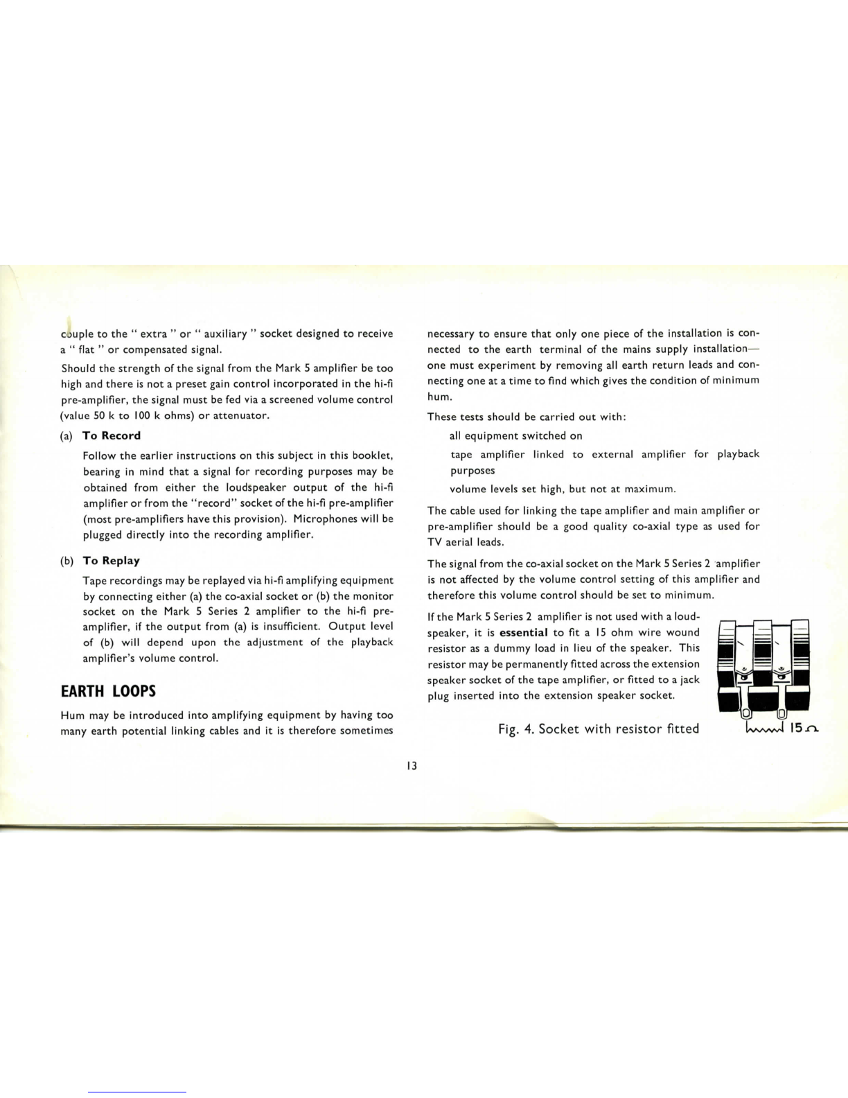
Ifthe
Mark
5
Series
2
amplifier
isnot
used
with
a
loud-
speaker,
itis
essential
to
fit
a
15
ohm
wire
wound
resistor
asa
dummyload
in
lieu
ofthe
speaker.
This
resistor
maybe
permanently
fitted
across
the
extension
speaker
socket
ofthe
tapeamplifier,
or
fitted
toa
jack
plug
inserted
into
the
extension
speaker
socket.
Fig.
4.
Socket
with
resistor
fitted
15
J~\.
13
Maintenance
TO
CLEAN
For
the
continuedefficientoperating
ofthe
machine,
itis
essential
to
ensure
that
the
heads,
pinchwheel
and
tapeguides,
are
clean
and
freefromtapeoxide.
A
very
thin
film
of
dirt
or
oxide
onthe
heads
will
seriously
mar
the
frequencyresponse
and
reduce
the
volumelevel,
whilst
oxide
onthe
pinchwheel
and
guides
may
cause
tape
slipping—apparent
tothe
listener
asa
variable
change
in
pitch
ofthe
recordedsounds.
We
recommend
the
cleaning
kit
marketed
by
Messrs.
METRO-
SOUND
M.F.S.
Co.
Ltd.,
I9a
BuckinghamRoad,London,N.I,
and
known
as
KLENZATAPE.This
kit
will
enable
the
heads
tobe
quickly
and
efficientlycleaned.
The
tapeguides
and
pinchwheelshould
be
cleaned
with
methy-
latedspirits,
but
careshould
be
taken
to
prevent
this
spirit
being
spilt
onthe
plastic
head
covers.Methylatedspirits
may
also
be
used
ona
lightlydampenedlinen
cloth
for
cleaning
the
heads.
REMOVAL
OF
AMPLIFIER
Two
domedscrews
FI-F2
(Fig.
I)are
used
to
hold
the
amplifier
inthe
cabinet,
andthe
removal
of
thesescrews
will
enable
the
amplifier
tobe
lifted
from
the
cabinet
for
examinationand,
if
necessary,
operation
whilst
"
live."
Donot
disconnect
the
amplifier
from
the
power
unit
unless
the
mains
switch
isOFF
otherwise
excessive
voltage
will
build
upinthepower
unit
and
damage
will
occur.
REMOVAL
OF
DECK
The
deck
is
covered
bya
steelmaskwhichmust
be
removed
to
gain
access
tothe
four
boltswhichclamp
the
deck
tothe
mounting
brackets.
DONOT
remove
the
four
screws
from
the
sides
ofthe
cabinet—
these
screws
retain
the
deckmountingbrackets
in
position.
The
mask
maybe
lifted
from
the
deckafterremoval
ofthe
deckknobs,
adjustable
guide,plastic
head
covers
andthetwo
smallscrews
near
the
spoolholders.
When
lifting
the
deck,careshould
be
taken
to
avoiddamaging
the
cables
coupling
amplifier
and
deck.
REMOVAL
OF
POWERUNIT
After
removal
ofthe
amplifier
and
deck,
the
power
unit
will
be
14

readily
accessible
andmaybe
entirely
removed
from
the
cabinet
by
removing
the
clampingscrews.
(Be
sure
to
replace
spacers
when
refitting.)
The
power
unit
must
notbe
operated
unless
loaded
bythe
amplifier,
otherwise
high
voltages
will
build
upand
cause
damage.
OILING
The
motors,
flywheel,
idler
wheel
and
pinchwheel
are
fitted
with
the
"
oilite
"
oil-retaining
bearings
and
therefore
will
seldom
require
oiling.
Not
morethan
one
drop
of
thin
machine
oil
will
be
needed
to
each
bearing
per
1,000
hours'use.
Oil
must
notbe
allowed
to
contaminate
the
rubbertyres
ofthe
idler
and
pinchwheels.
Oilonthe
periphery
ofthe
flywheel
will
cause
the
tape
speeds
to
become
erratic.
BRAKES
Mechanical
braking
is
employed;
cork-lined
levers
act
upon
the
spoolholderdrums.
BRAKE
ADJUSTMENT
Should
tapespillageoccur(whenusingreels
of
equal
size)
check
adjustment
of
brakes,whichshould
beas
follows:
With
rewind
and
record/playbackswitches
to
"
STOP,"adjust
the
gap
betweenbrakelevers
andthe4
B.A.
adjustablescrews
in
actuatingbar,
to
-^".
Adjustment
of
thesescrews
canbe
carried
out
after
releasing
the
lock-nuts.Always
tighten
lock-nutsafterwards.
Should
spillageoccurwhen
thegapis
correct,
shorten
the
brake
spring
by
approximately
£".
(NOTE
that
when
using
reels
of
unequal
size,centrifugalforces
will
be
unequal
and
tapespillage
may
occur.)
STABILISER
BRAKE
This
isa
smallbrakewhichoperates
onthe
feed-spoolholder
drum
to
stabilise
the
tapefeed
on
record
and
playback.
Itis
essential
that
thisbrakeshould
have
very
light
pressure
onthe
feed
spoolholderotherwise
thewow
content
will
rise
asthe
tape
nears
the
centre
ofthe
reel.
The
pressureshould
be
justsufficient
to
prevent
a
full
reel
of
tape
unwindingjerkilyduringrecordandplayback.
MOTORS
Threemotors
are
employed
onthe
Mark
5
Series
2
deck—
hysteresis
synchronoustype
for
driving
the
capstan,
5
watt
shaded
pole
for
rewinding,
and3
watt
shaded
pole
for
take-up.
15

MOTOR
TEMPERATURE
These
motors
are
designed
to
operate
at
high
temperatures—
50°C
plus
ambient.
SPEED
CHANGE
SWITCH
This
three-positionswitch
gives
speeds
of:
(a)
with
I"
diameter
capstan
sleeve—IS,
7^,
3J
i.p.s.
(b)
with
j"
diameter
capstan
sleeve—7\
3|,
IJ
i.p.s.
(See
note
on
"
Capstan
sleeves.")
Important:
should
the
user
desire
to
dispense
with
the
15
i.p.s.
and
permanently
usethe
small
capstan
sleeve,
giving
speeds
of
IJ,
3f
and
7^
i.p.s.,
the
cable
between
speed
switch
and
resistor
RSI
should
be
removed;this
will
enable
the
take-up
motor
to
operate
at
a
lowertemperature
inthe
highest
speed
position.
(NOTE:
At
15
i.p.s.
full
mains
power
is
applied
tothe
take-up
motor
to
givefaster
initial
take-up
and
preventtapespillage.)
CAPSTAN
SLEEVES
Two
sleeves
are
provided
of
approximately
I"
and
^"
diameter.
The
I",
used
in
conjunction
with
speed
switch,
gives
speeds
of
15,
7j
and
3J
i.p.s.,
whilst
the
\"
isfor
speeds
of
7^,
3|
and
IJ
i.p.s.
(See
note
on
"
Speed
ChangeSwitch
")
The
sleeves
are
retained
onthe
capstan
shaft
with
grub
screws.
Ensure
screw
is
tight,
or
speed
fluctuations
will
occur.
(NOTE:
The
capstan
sleeve
should
be
fixed
with
the
grubscrew
near
the
deck
plate,allowing
£"
clearance
between
endof
sleeve
and
deckplate.)
These
illustrationsshow
how
simple
itisto
gain
access
toall
parts
ofthe
BrenelI
Mark
5
Series
2
deck
simply
by
removing
the
maindrive
motor
plate.
A
Take-up
motor
C
Maindrive
motor
D500
ohms
10
watt
resistor
F
Feed
motor
G
Suppressorunits
16

To
gain
access
to
idler
pulley
(Z)
remove
screws
N andBand
swing
speed-changing
mechanism
so
that
idler
is
clear
of
motor
plate.
Xisthe
steppedpulley.
Uisthe
lower
bearing
forthe
capstan
spindle.
Fig-
6
v
H
Mechanicalbrake
K
Speed
changeswitch
M
Rewindswitch
P
Flywheel
Fig.
5
^
Q
Headleads,anchoring
strip
S
Recordplayback
switch
T
Suppressor
units
U
Lower
bearing—capstan
spindle
17
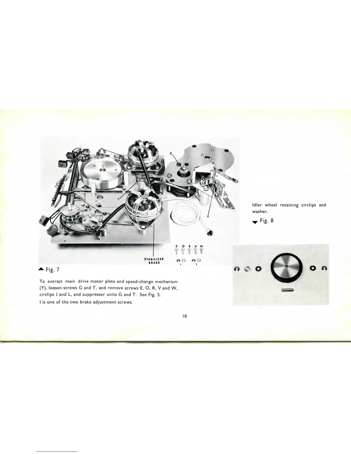
Fig.
7
To
extract
main
drive
motor
plate
and
speed-changemechanism
(Y),loosenscrews
G andT,and
removescrews
E,O,R,V andW,
circlips
J andL,and
suppressorunits
G andT.See
Fig.
5.
1
isoneofthetwo
brakeadjustmentscrews.
Idler
wheel
retaining
circlips
and
washer.
v
Fig.
8
18

PRESSURE
PAD
RELEASE
MECHANISM
An
adjustablecrescent-shapedlever(seeFig.
2)
controls
the
move-
ment
ofthe
leverreleasing
the
pressure
pads
(Nin
Fig.
2).
This
is
carefully
setup
before
the
deck
leaves
the
works,
butin
case
adjustment
is
required
the
following
setting-upprocedure
should
be
adopted:
With
I"
diametercapstan
sleeve
in
position,
switch
to
playback
and
adjust
the
crescentlever
so
that
when
the
pressure
pads
meet
the
headfaces,approximately
-fa"
freemovement
ofthe
releasing
baris
possible(see
V on
Fig.
2).
ERRATIC
TAPE
SPEED
Will
be
caused
ifOILis
allowed
to
accumulate
onthe
flywheel,
idler
or
motor
pulley.
FAULT
FINDING
Loss
oftop
response
and/or
output
from
record/playback
heads
and
incompleteerasure:
The
above
condition
canbe
caused
bythe
tapebeingunable
to
make
intimate
contact
with
the
face
ofthe
record/playbackhead
orthe
erasehead
owing
toa
build-up
of
oxidedust.
REMEDY:
Cleanhead
faces
with
soft,clean
cloth
dampened
with
methylatedspirits(NOTPETROL).
Atthe
same
time
clean
the
tapeguides,tensioningpins
and
capstan
sleeve.
Check
for
distortion
of
pressure
pads
and/orarms.Check
springtension
of
arms.
The
armsshouldmovefreely
on
their
posts.
WOWAND
FLUTTER
Listed
below
are
some
ofthe
possible
causes
ofwowand
flutter:
(a)
Driving
members
dirty
and/or
greasy
(b)
Eccentricpinchwheel
(c)
Stabiliserbrakeunder
too
great
tension
(d)
Idler
wheel
fouling
steppedpulley
(e)
Loose
capstan
sleeve
(f)
Tight
bearings
of
flywheel,pinchwheeland/or
idler.
19

REMEDIES
FORWOWAND
FLUTTER
(a)
Clean
with
soft
cloth
dampened
with
methylated
spirits:
the
flywheel
rim
capstan
sleeve
tape
guides
head
faces
stepped
motor
pulley.
(b)
Changepinch-wheel;avoidcontact
with
oil.
(c)
Adjust
the
pressure
ofthe
stabiliserbrake
tothe
minimum
amountrequired
to
prevent
the
tapespoolunwinding
ina
jerkymannerduring
the
record
or
playbackoperations.
Adjustment
is
effected
by
releasing
the4
B.A.
fixing
nutand
resetting
the
position
ofthe
brakelever.
(d)
Adjust
height
of
steppedpulley
to
ensureonly
one
section
is
operativeaccording
to
speed
in
use.
(e)
Ensure
that
fixing
screw
is
tight.
(0
Usually
dueto
dirt—clean
and
lightly
oilthe
bearings.
Specification
TAPE
SPEEDS:
l|,
3|,
7^
and
IS
i.p.s.
MOTORS:
Three(SynchronousHysteresistype
for
driving
capstan).
WOWAND
FLUTTER:
Less
than0.05%
at
15
i.p.s.
0.1%
at
7±
i.p.s.
0.15%
at
3f
i.p.s.
0.25%
at
IJ
i.p.s.
Please
note,
thesefigures
arefor
Record/Replay
andNOT
Record
only.
RECORD/PLAYBACK
FREQUENCY
RESPONSE:
15
i.p.s.
40 c/s to
over
15
kc/s
±2
dB
7£
i.p.s.
40c/sto
14
kc/s
±3dB
3|
i.p.s.
40c/sto
11
kc/s
±3dB
IJ
i.p.s.
40c/s
to
6
kc/s
±3dB
Measured
at
Ext.
Amp
Socketacross
47k ohm
load.
AMPLIFIER
RESPONSE:
40c/sto20
kc/s
±3dB.
BASS
CONTROL:
9 dB
variation
at65
c/s.
SIGNAL/NOISE
RATIO:
Unweighted—including
hum—45
dB.
SENSITIVITIES:
FOR
PEAK
MODULATION
A
MINIMUM
SIGNAL
OF:
MICROPHONE:
2.0
mV
(Impedance
I
Megohm).
RADIO:
80mV
(Impedance
220k
ohms).
20
Table of contents
Popular Recording Equipment manuals by other brands


Roland
Roland Camm-1 CX-24/12 manual

Bespoke
Bespoke Scoreboards Play cricket scorer pro Set up and operating instructions

Korg
Korg Tone Works Pandora PX4D owner's manual

GRASS VALLEY
GRASS VALLEY K2 HD-00 quick start guide

Lexicon
Lexicon REFLEX - user guide

Kurzweil
Kurzweil MIDIBOARD - MUSICIAN S BOARD manual