Brett-Guard 10A User manual

®
OPERATORS MANUAL
Original Style
10A, L, LB, LR, LRB
Caution: Read all instructions carefully.
SAVE THESE INSTRUCTIONS.
Refer to them often and use them to instruct others.
Date Purchased:
Where Purchased:
Address:

2
Table of Contents
General Product Safety Warning.............. 2
Warnings ................................................ 4
Component Descriptions......................... 4
Operating Instructions............................. 5
Ripping Reminders ................................. 7
Cross Cutting Reminders ........................ 7
Assembly and Installation ....................... 8
Brackets and Rear Plates........................ 8
Maintenance Instruction ......................... 9
Parts..................................................... 10
Warranty............................................... 12
A Word About Your New Brett-Guard
The Brett-Guard Table Saw Safety Tool is designed for the discriminating
woodworker — The craftsman who wants quality, function, and performance
without sacrificing safety and flexibility. Brett-Guard is designed to overcome
the objection “you can’t guard that operation.” It’s patented features make it
more than just a guard, it’s really a safety tool integral to the cutting operation.
The fully adjustable inverted box-type transparent shield provides greater
safety while performing virtually any cutting operation including rip, dado,
spline, tenon, groove, etc.
General Product Safety Warning
As with all products there are certain hazards involved with their
operation and use. Using any product with respect, caution, and common
sense will considerably lessen the possibility of personal injury. Safety is a
combination of staying alert, knowing how the product works, and knowing
how to properly use the product. To use any product safely you should plan
ahead and practice the proper steps prior to actually using the product. If
safety rules and instructions are overlooked or ignored, personal injury to the
operator or other people in the area may result. Safe operation of any product
requires that you read and understand the product instructions and all labels
affixed to the product.
Always read and follow all instructions and safety rules carefully.
This product is designed for certain uses only. This product or any of
it’s parts shall NOT be altered, changed, or modified in any way and/or used
for any other use than it’s designed for. If you have any questions about it’s
proper care or use DO NOT use the product until you have written HTC and
we have advised you in writing.
HTC Products — Technical Support
1161 Rankin Dr.
Troy, Michigan 48083
(800) 624-2027
www.htcproductsinc.com
General Safety Rules
1. For your own safety, read instruction manual before operating the
tool, Know the tool. Read and understand the owner’s manual and labels
affixed to the tool.
2. Keep work area clean. Cluttered areas and benches invite accidents and
create fire hazards.
3. Wear proper apparel. Do not wear loose clothing, gloves, neckties,
bracelets, drawstring, necklaces, ornaments, rings, wristwatches, or jewelry
of any kind. They can get caught and pull you into moving parts.
4. Avoid dangerous environment. Keep alert to potential hazards in the
working environment. Do not use tool in situations such as damp or wet
locations or in the presence of highly combustible materials, dust, and
flammable liquids, fumes, vapors or gases.
5. Keep children and visitors away. All visitors should be kept a safe
distance from work area. Don’t let visitors contact tool or power cord.
Anyone visiting the work area should wear appropriate protective devices.
6. Wear safety goggles. Wear safety goggles (not glasses) at all times. All eye
protection must comply with the ANSI Z87.1 standard for eye protection.
Everyday eyeglasses only have impact resistant lenses, they are NOT safety
glasses.
3
7 Drugs, alcohol, or medication. Stay alert. Watch what you are doing. Use
common sense. Do not operate tool when you are tired, upset, ill, or while
under the influence of drugs, alcohol, or medication.
8. First aid. Have at least one person with first aid training and first aid kits
approved by American National Red Cross available at all times.
9. Fire extinguisher. Familiarize yourself in the use of a portable fire
extinguisher. Post the telephone number of the local fire department. Also
develop and know emergency procedures in case of fire.
10. Smoke Detector. To increase protection against fire install smoke
detectors. For proper selection and installation guidelines contact your local
fire department.
11. Use right tool. Don’t force tool or attachment to do a job it was not
designed for.
12. Don’t force tool. It will do the job better and safer at the rate for which it
was designed.
13. Secure work. Keep hands well away from moving parts, saw blades, and
other cutting tools. Use a push stick or push block to hold or guide the
work when working close to cutting tool. Use jigs, fixtures, miter gauge,
clamps or vises to hold work when practical.
14. Never leave tool running unattended. Turn power off. Don’t leave tool
until it comes to a complete stop.
15. Keep guards in place. Be sure that guards, hold-downs, and anti-kickback
devices are in working order, are positioned properly, and are in proper
adjustment and alignment.
16. Remove adjusting keys and wrenches. Form the habit of checking to see
that keys and adjusting wrenches are removed from the tool before turning
the tool on.
17. Cutting tool exposure. Adjust the tool for minimum exposure of cutting
tool necessary to perform the operation.
18. Direction of feed. Feed work into a blade or cutting tool against the
direction of rotation of the blade or cutting tool only.
19. Don’t overreach. Keep proper footing and balance at all times.
20. Never stand on tool. Serious injury could occur if the tool is tipped or if
the cutting tool is accidentally contacted. Do not store materials above
or near the tool in such a way that it is necessary to stand on the tool to
reach them.
21. Avoid accidental starting. Make sure switch is in the “OFF” position
before plugging in tool. Do not carry a plugged in tool with finger on switch.
22. Inspect workpiece. Always inspect workpiece to make sure there aren’t
any nails or foreign objects in the part of the workpiece to be worked on.
23. Plan ahead. Mentally plan ahead to protect your eyes, hands, body, face
and hearing. Do layout assembly, setup work, material handling, and
planning before using tool.
23. Disconnect tools. Always turn tool “OFF” and disconnect the cord from
the power source before tool is serviced or when installing or removing
accessories such as blades, bits, or cutters, etc.
25. Maintain tools with care. Inspect tool before each use. It is
recommended that the general condition of any tool be examined before
it is used.
26. Check damaged parts. Before further use of the tool, a guard or other
part that is damaged should be carefully checked to ensure that it will
operate properly and perform its intended function.
For your own safety and best results
read instruction manuals before operating.
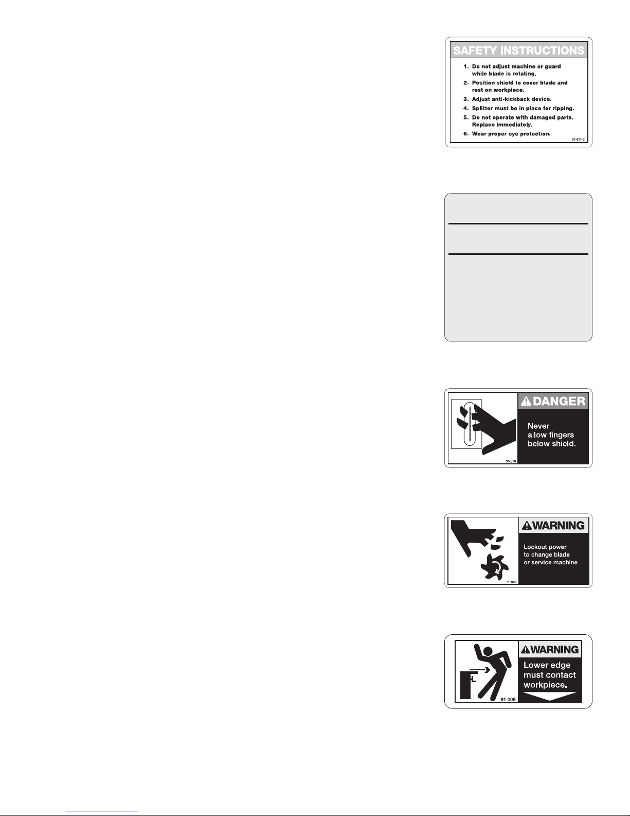
CAUTION
TABLE SAWS ARE VERY DANGEROUS.
• Use only with guard in place and
properly adjusted.
• Never adjust guard while saw is running.
• Never allow hand under edge of shield.
• Always wear eye protection.
Form No. B-0106
Part No. 91-011-2
Part No. B-0106
Part No. 91-010
Part No. 91-008
Part No. 91-009

27. Ground all tools. Make sure wiring codes and recommended electrical connections are followed and that tool is
properly grounded.
28. Outdoor use extension cords. When tool is used outdoors, use only extension cords marked “suitable for use
with outdoor appliances - store indoors when not in use.”
29. Ground Fault Circuit Interrupters - (GFCI’s) provide additional means to reduce serious electrical shock while
using a power tool. They are easily installed between the power receptacle and the cord. Leakage of current will
shut off the tool, preventing possible serious injury from electrocution.
WARNING
The dust generated by most materials including plastics, metals, wood, and wood tools can be injurious to your
health. Always operate tool in a well ventilated area and provide for proper dust removal. Use appropriate dust
collection systems whenever possible.
Table Saws Are Very Dangerous
All Table Saws are inherently dangerous and should never be used by anyone who is not thoroughly trained and
experienced. The Brett-Guard Table Saw Safety Tool, properly installed and used under proper supervision, can
help to protect an operator against injury from many saw hazards such as coming in contact with the saw blade,
kickbacks and flying splinters but NOTHING can protect an operator if proper operating procedures are not followed.
It is the responsibility of those making the set-up on a table saw to first determine if there is not a safer way to
accomplish the desired result.
Component Descriptions
Components
1. Vertical Adjustment Crank Handle — The handle on top of the saw guard housing raises and lowers the
transparent safety shield assembly to fit the height of the workpiece.
2. Locking Knob — The hand knob located on top of the saw guard housing, next to the Vertical Adjustment Crank
Handle, is used to lock the saw guard housing assembly to the mounting plate and to release it.
3. Transparent Safety Shield — An inverted box type guard that permits the saw blade and work-piece to be seen.
Must always be in contact with the workpiece. The Anti-Kickback mechanism is an integral part of the shield.
4. Horizontal Shield Adjustment Lock Knobs — Hand knobs located on the front and rear of the saw guard housing
lock the 1/2" diameter horizontal bars in position.
5. Anti-Kickback Adjustment Lock Knob —Raises and Lowers the Anti-Kickback device located in the safety shield.
6. Shield Support Rods —Connects the Safety Shield to the adjustment mechanism.
7. Locking Rod — Locks the Safety Tool in the Down and Locked Position. Is rotated by the Locking Knob.
8. Vertical Adjustment Screw — Provides positive control for the raising and lowering of the safety Shield Assembly.
It is operated by the Vertical Adjustment Crank Handle. Lubricate frequently for smooth operation and extended life.
9. Vertical Guide Bars — Serves to keep the Safety
Shield stable. When the Safety Shield begins to get
loose and sag these must be replaced along with their
companion bushings.
10. Housing — The complete raising, lowering, locking,
and adjustment mechanism.
11. Splitter — Mounts to the saw blade trunnion and must
be directly in line with the saw blade. It serves to keep
the kerf of the workpiece from closing up on or pinching
the saw blade. This must be in place during all cutting
operations where the saw blade is cutting all the way
through the workpiece. Thin kerf splitter also available.
4
5
3
6
11
7
2
1
13
8
9
10
4
Figure 1

Operating Instructions
The use of the BRETT-GUARD Table Saw Safety Tool (Guard) is basically quite simple. But, due to the serious nature
of operating a table saw, there are many factors to be considered. The following pages show most of the important
factors to consider for safe table saw operation. It must be pointed out that some operations are safer, when done
with other equipment.
WARNING: NEVER MAKE ANY ADJUSTMENTS WHILE BLADE IS ROTATING.
Locking Guard into Position
1. Position the Saw Guard Housing over the Mounting Plate. Align the two (2) locator pins with the two (2) holes in the
Mounting Plate. Set the housing on the plate.
2. Rotate the Locking Knob until the Locking Rod drops
into the key hole on the Mounting Plate.
3. Rotate the Locking Knob clockwise. A mechanical stop
is reached after 1/2 revolution. The guard is now locked
to the Mounting Plate.
NOTE: You should notice some resistance when
rotating the Locking Knob. If not it should be adjusted.
Refer to maintenance instructions on page 9.
Unlocking Guard
1. Make sure that the power is off to the machine.
2. While supporting the guard, rotate the Locking Knob counter-clockwise and lift.
WARNING: NEVER LEAVE THE BLADE UNGUARDED.
Procedure to Change / Access Saw Blade
1 Disconnect power to the machine. Observe OSHA Lock-Out Procedures.
2. Loosen the horizontal shield adjustment Lock Knobs and slide the shield toward the housing.
3. When saw blade service is completed, return shield to proper position
4. Restore Power.
Anti-Kickback Adjustment
The anti-kickback mechanism is an integral part of the Safety Shield and the Anti-Kickback Adjustment Knob (5) is
located on the top of it. The Anti-Kickback fingers are spring loaded. The Knob provides an adjustment range from
Retracted to Full Pressure. It is recommended for most table saw set-ups that the Anti-Kickback mechanism be engaged.
Warning: The safety shield must be in contact with the workpiece for the Anti-Kickback Device to function. The
Anti-Kickback Device is effective only when the Brett-Guard is mounted on the left side, and the Anti-Kickback
Device engages the workpiece. The Anti-Kickback Device is inoperative when the Brett-Guard is used in the right
and rear positions.
Safety Shield Adjustments
Vertical Adjustments
The height of the Safety Shield is very important. The Vertical Adjustment Crank Handle is used to raise and lower the
shield. (See Page 4 - Component Descriptions)
Horizontal Adjustments
1. With the guard locked to the mounting plate, loosen the two Horizontal Shield Adjustment Knobs.
2. Position the shield right or left as required. The recommended position is for the Anti-Kick Fingers to be centered
over the line of the blade. Refer to typical set-ups page 6 and 7.
3. Retighten the Lock Knobs.
5
Engage Material
Anti-Kickback Fingers

6
Warning: For the Anti-Kickback device to function and/or the Shield to serve as a hold-down device, it is
imperative that the shield be adjusted so that the lower edge of the shield applies a light pressure to the top of
the workpiece.
Leveling
The Safety Shield must be kept parallel with the top of the saw table or the Anti-Kickback feature on the guard will not
function correctly. This detail is very important and should be checked regularly. A series of Set Screws are used to level
the mounting plate to the saw table. Refer to Assembly and Installation.
Squaring
The edge of the Safety Shield is to be kept parallel to the saw fence. To adjust-
1. Loosen the four (4) mounting screws that secure the Safety Shield to the Shield Support Rods.
2. Lock the saw fence up against the side of the shield. Then retighten the four (4) mounting screws.
Caution: The saw table and fence must first be squared to the saw blade
Typical Set-ups
Warnings:
1. Never operate a Table Saw without a properly mounted and positioned Saw Guard. Use of an improperly guarded
saw will result in serious injury.
2. Properly position guard BEFORE turning on the saw motor.
3. Do not adjust guard or blade position while saw motor is running or even while blade is rotating.
4. Make certain the Anti-Kickback device is properly adjusted.
5. Never reach or let hands slip under the shield.
6. Always wear proper eye protection while operating a table saw.
7. LOCKOUT POWER before changing the blade or servicing the machine.
8. Worn or damaged parts, on the saw or the guard, must be replaced before operation is continued.
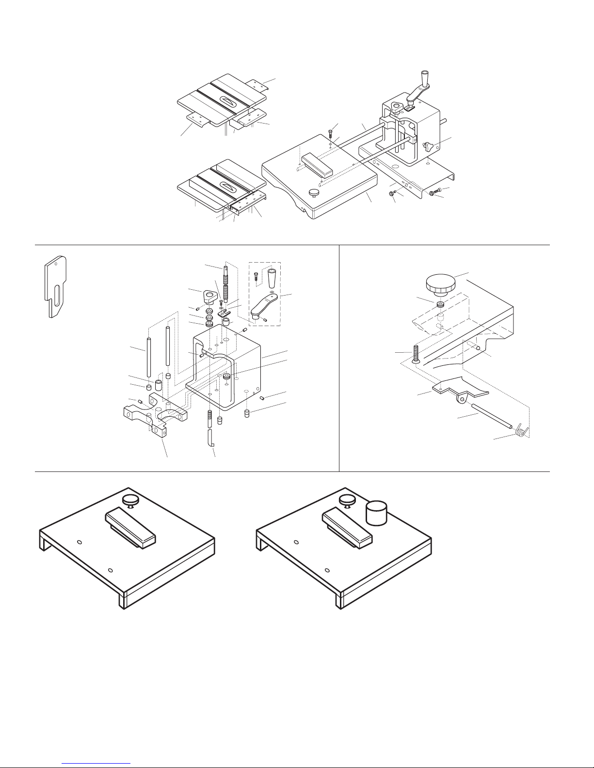
When ripping narrow stock always use a Push-Stick. Always use outfeed support for long stock.
Lip prevents plate
from slipping too
far under the shield
and engaging the
Anti-Kick fingers.
Push Plate Lip
Small
material
Direction of feed
Blade
Material
Splitter
Inline with blade

Cross-Cutting
Tenoning
Tenoning
7
Ripping Reminders:
1. Mount the Brett-Guard on the left side of the Table
Saw.
2. Always have the splitter installed
3. Raise the shield enough to clear the blade. Position
shield so the blade is about 1" inside the edge of
the shield.
4. Shield should rest gently on the wood being cut.
5. Always engage the Anti-Kickback mechanism.
6. Always stand to the side of the blade.
7. Use proper size push plate for small pieces.
Cross-Cutting Reminders:
Note: The original Brett-Guard can be used in any
position for cross-cutting
1. When possible use the Brett-Guard in the left
position to take advantage of the Anti-Kickback
mechanism
2. Always have the splitter installed.
3. Always stand to the side of the blade.
4. Rip Fence should be positioned on the opposite side
from the guard, away from the material being cut, or
removed completely.
5. Always lower the shield so that it rests gently on the
workpiece.
Dadoing
Rabbiting Cross-Cutting
Tenoning

8
Assembly and Installation
The original model Brett-Guard is shipped from the factory with the mounting plates and hardware specific to your order.
1. Attach the two steel shield support rods to the acrylic shield with four (4) #10-24 x1" screws and nylon washers in
the threaded holes provided in the steel rods. Position rods on the inside of the shield, with nylon washers between
the shield and the head of the screw.
2. Thread two (2) 5/16 - 18 x 1" Lock knobs into the Brett-Guard housing as shown on Page 4 - Component Description.
3. Insert the shield support rods into the housing slide and lock into position with the knobs installed in previous step.
Set this assembly aside.
4. Review Figure 3. You will note the key shaped holes in the left and right plate must correspond exactly to the axis of
the saw arbor. Locate and mark line “T” on the saw surface, with an easily removable marker or pencil.
5. If a rear plate is to be installed, locate and mark line “L” as well, using the proper off-set as indicated in Figure 3.
6. Clamp the mounting plate onto the edge of the table, flush with the surface, key shaped hole toward the blade. Key
shaped hole in plate should be centered on the line located in Step 4.
7. Mark the locations of the mounting holes, using the large holes (2) in the plate as your guide.
8. Remove the mounting plates and center punch the locations of mounting holes marked in previous step for drilling.
9. Drill 7/16" through holes in the table edge at the center punched locations. If the table edge is thicker than 1/4", you
may want to drill and tap the holes.
10. Attach the mounting plate to the table edge with 3/8" -16 x 1" bolts, washer, lockwasher and hex nuts provided.
11. Leveling the plate to the table surface is easily accomplished by installing the provided set screws above or below
the mounting bolts. Slightly loosen the mounting bolts and tighten the set screws to gain the required adjustment.
12. Repeat this same procedure for mounting right side plates.
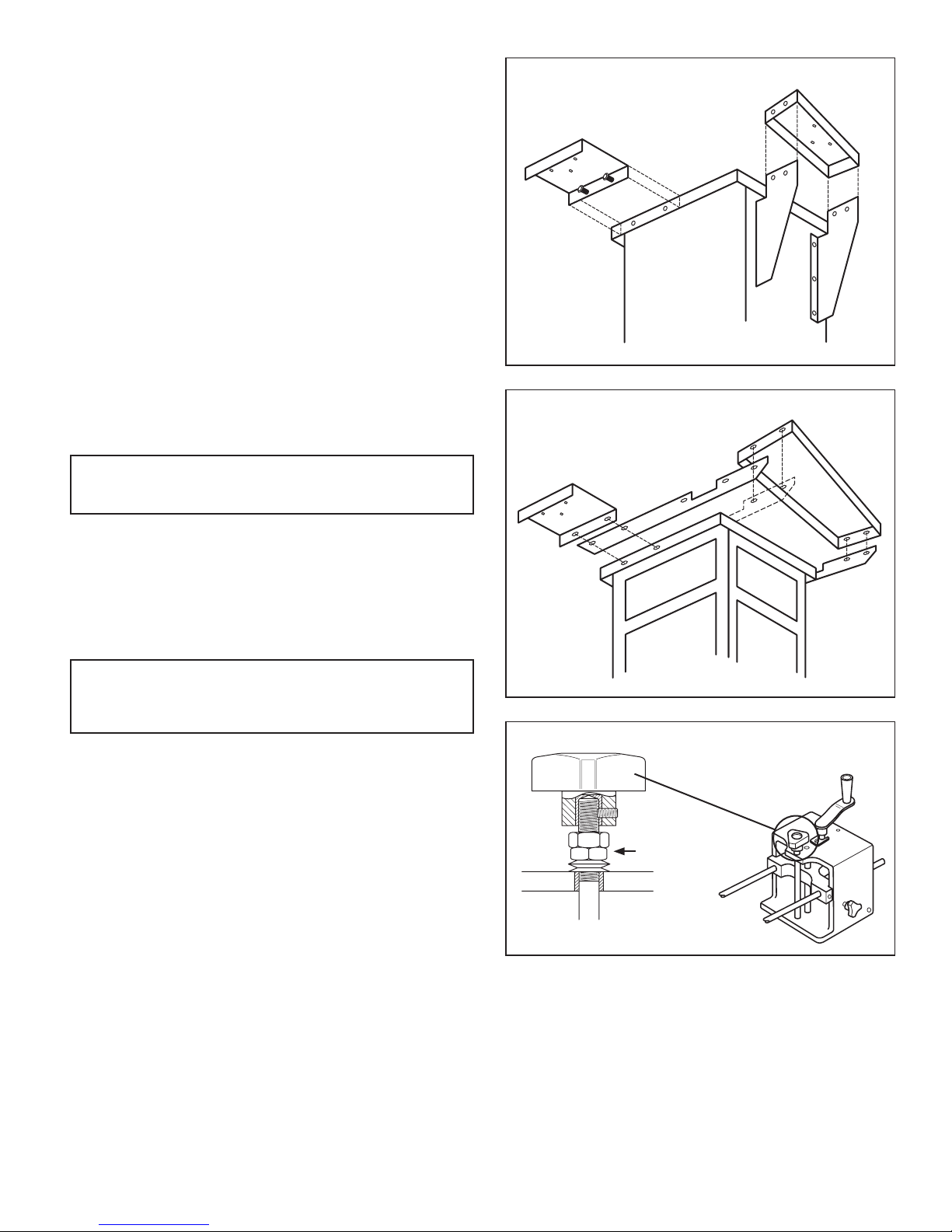
Brackets and Rear Plate Installation
The type of arrangement for mounting a rear plate will vary based on your saw and was determined at the time of order.
Review Figures 4 and 5.
1. Fasten the left and right brackets to the rear box plate on the inside edge. Use two (2) 5/16" - 18 x 1" bolts,
washers, lockwashers, and hex nuts on each side. Make sure the key shaped hole will face the saw blade.
Note - Steps 2-5 will require a helper.
2. Using the reference line drawn on the table saw, (Figure 3) align the key shaped hole with mounting brackets held
against cabinet back.
3. Check to be sure the plate is low enough to permit clearance of the rip fence and miter gauge guide bar.
4. Now check the side clearance between the miter gauge guide and the Brett-Guard housing.
5. Mark and center punch the hole locations in the cabinet
using the holes in the mounting brackets as a guide.
Drill 1/8" pilot holes at the center punched locations.
Then enlarge with 11/32" drill to accommodate 5/16"
mounting bolts.
6. Attach mounting brackets to the cabinet with four
5/16" - 18 x 1" bolts and flat washers from the inside
of the cabinet. Feed the bolt through the mounting
bracket and secure with flat washer, lock washer, and
hex nut.
7. Before tightening the bolts, lock the Brett-Guard onto
the rear plate. Lower the shield until it is about 1/4”
from the table top. Tap the mounting plate gently until
the shield is level with the table top.
8. If the guard is not parallel with the blade, insert shims
under the left or right bracket until it is parallel. Tighten
Left
Plate
Right
Plate
Key Shaped
Hole
Key Shaped
Hole Key Shaped
Hole
Line T
Line L
Blade
Distance from Line L to Blade for Model 10A - 4"
Figure 3
9
all bolts.
Arms and Rear Plate Installation
1. Remove the existing extension wings from the saw.
2. Check the alignment of the pre-drilled holes in the
arms, with the existing holes in the table edge. If they
do not match, you will need to drill new through holes
in the arms to match the existing holes in the table.
3. Remount the extension, sandwiching the arms
between the table and the extensions. Arms should be
flush or slightly below the table.
4. Attach the rear mounting plate to the arms using (4)
5/16" - 18 x 1" bolts, flatwashers, lockwashers and
hex nuts. Hand tighten only.
5. Lock the Brett-Guard onto the rear plate. Lower the
shield until it is about 1/4" from the table top. Gently
tap the plate until the shield is level with the table and
tighten all fasteners.
Maintenance Instructions
Warning: Disconnect all power from machine
before performing any service operations.
Safety Shield
The Safety Shield should be cleaned daily if used
continuously. Most sawdust can be blown off with
compressed air, if available. If not, brush or wipe off with a
soft grit-free cloth. Ordinary non-abrasive soap and warm
water or denatured alcohol will remove wood resins.
Warning: Do not use any solvents such as
acetone, benzene, carbon tetrachloride,
dry-cleaning fluid or lacquer thinner.
Locking Rod Adjustment
While turning the Locking Knob it should tighten slightly
before it reaches the locked position. If not make
adjustment as follows:
1. Put guard in the Down & Locked position.
2. Using two 11/16" wrenches, loosen the top of the two
nuts underneath the Locking Knob.
3. Turn the bottom nut until it begins to snug up.
4. While holding the bottom nut steady, with one wrench,
tighten the top nut against it, with the other wrench.
5. Check by turning the Locking Knob. If it is still loose,
repeat steps above. If it will not relock, back off on the
adjustment.
Right Rear
Figure 4
Right Rear
Figure 4
Locking Rod
Adjustment Nuts
Key Model No. Description Weight
(UPS)
A20030 Replacement ‘Plexiglas’ Shield for 10A Guards 6#
B 20030P Replacement ‘Plexiglas’ Shield w/2" Dust Port 6#
Parts
10
37 - “L”
37 - “B”
37 - “S”
44, 45
37- “R” 42
28
29
36
26
30
32
31
33
34
35
38
3941
37
27
25
24
2
5
6
4
3
10
1
18
8
19
9
17 21
7
16
15
23
22
20
40
43
AB

Key Description Part# Qty.
* Housing Assembly, ‘Original’ style 20500 1
See Note #1
1 Housing Body 20001 1
2 Crank Rod, threaded 20008 1
3 Crank Rod, Bushing, upper 20011 1
4 Bushing Retainer Plate 20012 1
5 Retainer Screw (1/4-20x5/8") 20013 1
6 Lock Washer 20014 1
7 Crank Rod Spacer Washers 20016 3
8 Crank Rod Bushing, threaded 20009 1
9 Set Screw (for above) (1/4-20x1/4") 20017 1
10 Crank, height adjusting, complete 20006 1
15 Locating Pin 20021 2
16 Set Screw (for above) (1/4-20x1/4") 20017 2
17 Slide 20002 1
18 Guide Rod 20003 2
19 Guide Rod Bushing 20004 2
20 Set Screw (for #18) (1/4-20x1/4") 20017 2
21 Locking Rod, ‘Quick-Lock’ 20227 1
22 Spacer Washers, Locking Rod 20026 3
23 Locking Nut, Locking Rod 20033 2
24 Locking Rod Knob (incl. set screw #25) 20269 1
25 Set Screw (for above) (10-32x3/8") 20018 1
26 Lock Knob, shield adjusting rod G-102 2
27 Shield, clear, complete ----- 1
28 Mounting Screw (10-32x1") 20044 2
29 Washer, #10 Nylon 20046 2
Key Description Part# Qty.
30 Kickback Assembly Knob 20039 1
31 Kickback Actuator 20054 1
32 Kickback Threaded Insert 20038 1
33 Kickback Plate 20040 1
34 Kickback Shaft 20041 1
35 Kickback Spring 20042 1
36 Shield Support Rod, 24" 20025 2
36 Shield Support Rod, 30" 20027 2
37 “L/R” Mounting Plate, 20055 1
6”x12”x1-1/4”, channel, drilled
37 “B” Mounting Plate, 20066 1
6"x15"x1-1/4", box, rear, drilled
37 “S” Mounting Plate, 20071 1
6"x__"x1-1/4", overhead
38 Mounting Bolt (for above) (3/8-16x1"hex) 2
39 Flat Washer, 3/8" 2
40 Nut (3/8-16 hex) 2
41 Lock Washer (3/8") 2
42 Brackets & hardware for mounting 20075 1 pr.
#20066 to cabinet type saws
43 Support Arms & hdwe. for mounting 20076 1pr.
Rear Box Plates to open type saws
44 Splitter 20005 1
45 Splitter, “Thin-Kerf” 20284 1
Note #1: Consists of #1 thru #20
and lock rod #21 or #26
11
Parts

HTC Products
1161 Rankin Dr.
Troy, MI 48083
800-624-2027
www.htcproductsinc.com
LIMITED LIFETIME WARRANTY
Products manufactured by HTC Products are guaranteed
to be free from defects in material and workmanship under
normal use and service. HTC’s obligation under this warranty
shall be limited to repairing or replacing for the original
owner, at our option, any part of said equipment which
HTC’s examination shall disclose to its satisfaction to be
thus defective.
Any product or component claimed to be defective is to be
sent prepaid to: HTC Products, 1161 Rankin Dr., Troy, MI
48083 Attn: Warranty Department, together with a copy
of the original, dated sales receipt. Call for authorization
number before shipping.
This warranty does not apply to damages resulting from
shipping, accident, misuse, abuse or alteration.
Wear items (wheels, bearings, bushings, rubber feet, etc.)
are warranted for a period of 1 year. Consumable items (saw
guard shields) are warranted for a period of 60 days.
© 2013 HTC Products Part No. P034 Printed in USA
This manual suits for next models
4
Table of contents


