BRG DuraTime User manual
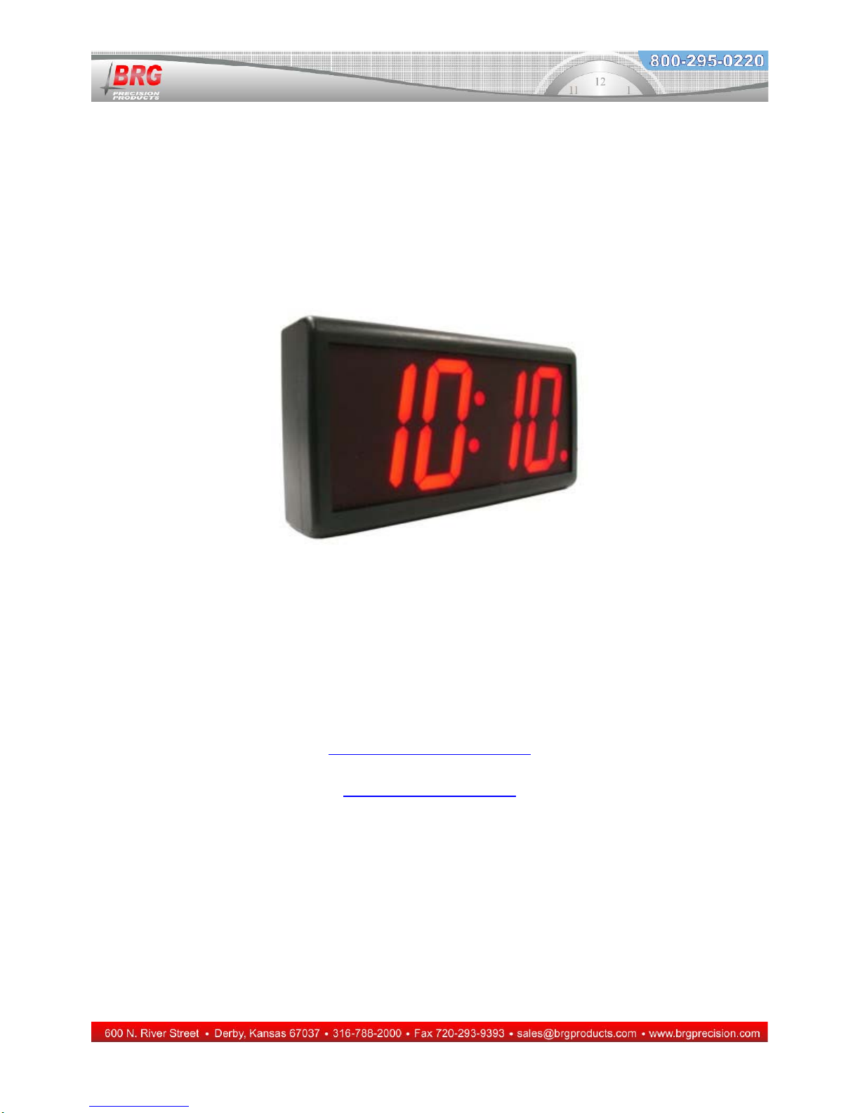
DuraTime Digital Clock
Installation and Operation Manual
BRG Precision Products
600 N. River
Derby, Kansas 67037
http://www.DuraTimeClocks.com
316-788-2000
Fax: (316) 788-7080
Updated: 12/8/2011
1

2
Operation
The DuraTime clock is based on super bright LED technology coupled with a very capable
microprocessor. The DuraTime microprocessor is able to store the user’s configuration in
duplicate. If the configuration becomes corrupt by someone configuring the display incorrectly, the
original customer configuration can be instantly restored. The Real Time Clock includes a high
accuracy temperature controlled oscillator as the standard time base and is accurate to a few seconds
per year without external synchronization. For absolute accuracy, the clock receives time updates
from one or more DuraTime master clocks.
Real Time Operation
There is normally no configuration required to connect the DuraTime digital clock to the wireless
network. Simply apply power to the clock within radio range of an active DuraTime network and
the clock will receive and update the display every second.
The Mega Real Time Clock employs a clock circuit with battery backup. The clock circuit will
maintain time for about ten years without power. When you receive your new clock and apply
power, you will see the clock already running. To manually change the time, simply press and hold
either the Up or Down buttons. The time will increment or decrement faster and faster as the
buttons are held. If the clock is within range of a DuraTime master clock, the clock will change to
the master clock time within a second or two.

3
DuraTime Clock Processor Configuration Menu
Processor Type
When the clock is displaying the time, Press the Up button to advance the time, or the Down button
to decrement the time. The longer the buttons are held down, the faster the time will change. Press
the Mode button to enter modes listed below.
First Menu
Level
Mode Number
Value
Range Mode Description and Instructions
Menu Selection
Operating
Value.
1- Press and hold the Mode button for 3-4 seconds, or until 01 appears on the
display. If the customer’s configuration was previously saved to secondary
memory, all segments on all displays will illuminate while the mode button is
held down.
2- Once in the menu system, use the Up and Down buttons to move to the
desired parameter address.
3- Once at desired parameter address, press the Mode button once to display
the parameter value.
4- Use the Up and Down buttons to change the parameter value.
5- Press the Mode button to return to the parameter address or press the
Timer Control button to save any changes and exit the menu system.
6- To exit the menu system, press the Timer Control button, or use the Down
button and move to parameter address 00. The clock will return to normal
display mode.
0. Change Time 00:00 to
23:59 or
12:00 AM to
12:00 PM
Simply press the Up button to advance the time, or the Down button to decrement the
time. The longer the buttons are held down, the faster the time will change. Press the
Mode button to enter modes listed below.
1. 01 to 31
Day of the Month
Pressing the Up button advances the days, pressing the Down button decrements the
days. Be sure to use valid day for any specific month. For example, do not enter a
day of 30 for the month of February.
2. 01 to 12
Month
Pressing the Up button advances the month, pressing the Down button decrements the
month.
3. 00 to 50 Year

4
First Menu
Level
Mode Number
Value
Range Mode Description and Instructions
Pressing the Up button advances the year, pressing the Down button decrements the
year.
4. 0-7
Blinking Colon
This mode configures various colon and sync indicator functions.
0= solid colon with no leading zero,
1=blinking colon with no leading zero
2=no colon with no leading zero
3=no colon with leading zero (display modes 2, 5, 17)
4=solid colon with leading zero (display modes 2, 5, 17)
5=disable blinking sync indicator
6= (default)Blink colon if serial sync is lost
7=Blink colon if serial sync is received
5. 0,1 12/24 Hour Display Format
0=12 hour display format (default), 1=24 hour display format
7.
-15-15 Display Intensity
1=minimum intensity, 15=maximum intensity (default),
0=enable auto-brightness (if installed)
-1 to -15 alters the effect of auto-brightness (if installed),
8. Adjust Time Received for Daylight Saving Time
0=disabled
1=enabled (default)
Removes daylight saving time from serial time data received. By default, the clock
expects to receive local time updates. If daylight saving time is active, then the time
received will be decremented one hour. The hour will be restored when the time is
displayed. If daylight saving time is not active, the time will be displayed as it is
received, in addition to any time zone offsets.
10. 0,1,2,3, Daylight Savings Time Automatic Switching
(unavailable on the Mega Timers)
0 = disabled
2 = UK daylight saving time,
3 = US daylight saving time rule (default),
When this feature is enabled, the time will automatically switch between standard and
daylight saving time.
11. -12 to +12 Time Zone Offset
(unavailable on the Mega Timers)

5
First Menu
Level
Mode Number
Value
Range Mode Description and Instructions
-12 to 12,
0=default
This feature allows adjusting time received over a serial sync line to the local time.
30 minute offsets are not available.
15. Leading Zero on Selected Display Modes
0=disabled,
1=enabled
When enabled, leading zeros will appear on display modes 2, 5, and 17.
18.
1-4
Number of Four Digit Displays Installed
1-4,
2=default,
This value determines how many four digit displays are installed. Double and four
sided displays may use a value of 1 to set all four sides to the same display. Other
combinations are possible.
19. N/A Displays the software version number of the clock.
20. 1-99
Sets various display modes for the first display
The following modes are available:
1 - ssxx – seconds left justified
2 - hh:mm – hours and minutes (default)
4 - nnnn – four digit year
5 - mm/dd – month and day
9 - xxxx – blank display
12 - mm:ss – minutes and seconds
13 - xssx – seconds centered
17 - dd/mm – international date format – day/month
20 - hh:mm – hours and decimal minutes
21. 1-99 Sets various display modes for the second display.
See Mode 20 for available display modes. The default display format is 13.
22. 1-99 Sets various display modes for the third display.
See Mode 20 for available display modes. The default display format is 2.
23. 1-99 Sets various display modes for the fourth display.
See Mode 20 for available display modes. The default display format is 2.
28. 0-99 Rotating Display Delay for Cycle Position 1 (Ver. 2.0 or later required)
4 = (default) Up to 3 display formats may be cycled or rotated. This mode setting
determines the time in seconds each display format is displayed. See Modes 31
through 36 to assign the desired display formats. For example, to display hours and
6
First Menu
Level
Mode Number
Value
Range Mode Description and Instructions
minutes on display 1 and a temperature alternating between degrees F and degrees C
on display 2, using temperature sensor port 1, then set Modes 31=2, 32=2, 34=24 and
35=25.
29. 0-99 Rotating Display Delay for Cycle Position 2 (Ver. 2.0 or later required)
4 = (default) Up to 3 display formats may be cycled or rotated. This mode setting
determines the time in seconds each display format is displayed. See Modes 31
through 36 to assign the desired display formats. For example, to display hours and
minutes on display 1 and a temperature alternating between degrees F and degrees C
on display 2, using temperature sensor port 1, then set Modes 31=2, 32=2, 34=24 and
35=25.
30. 0-99 Rotating Display Delay for Cycle Position 3 (Ver. 2.0 or later required)
4 = (default) Up to 3 display formats may be cycled or rotated. This mode setting
determines the time in seconds each display format is displayed. See Modes 31
through 36 to assign the desired display formats. For example, to display hours and
minutes on display 1 and a temperature alternating between degrees F and degrees C
on display 2, using temperature sensor port 1, then set Modes 31=2, 32=2, 34=24 and
35=25.
31.
0-99 Display Format – Display 1, Cycle Position 1
The display format will be displayed on display 1, in display cycle 1. See Mode 30 to
adjust the time delay before switching display formats.
32. 0-99 Display Format – Display 1, Cycle Position 2
The display format will be displayed on display 1, in display cycle 2. See Mode 30 to
adjust the time delay before switching display formats.
33. 0-99 Display Format – Display 1, Cycle Position 3
The display format will be displayed on display 1, in display cycle 3. See Mode 30 to
adjust the time delay before switching display formats.
34. 0-99 Display Format – Display 2, Cycle Position 1
The display format will be displayed on display 2, in display cycle 1. See Mode 30 to
adjust the time delay before switching display formats.
35. 0-99 Display Format – Display 2, Cycle Position 2
The display format will be displayed on display 2, in display cycle 2. See Mode 30 to
adjust the time delay before switching display formats.
36. 0-99 Display Format – Display 2, Cycle Position 3
The display format will be displayed on display 2, in display cycle 3. See Mode 30 to
adjust the time delay before switching display formats.
40. 0,1
Reverse Down Direction Timer at Zero
0=disabled – timer stops at zero
1=enabled (default) – timer reverses at zero
41. 0,1,2 Reverse Decimal Point
0=normal decimal (default),
1=reverse the position of the decimal point for discrete digit displays.
2=add colon to display modes 1 and 2 for discrete displays

7
First Menu
Level
Mode Number
Value
Range Mode Description and Instructions
3=turn on decimal when sync received, reset at midnight
4=turn on decimal when sync lost, , reset at midnight
5=turn on decimal when sync received
6=turn on decimal when sync lost
7=blank digits and turn on decimal when sync lost
44. 0-2
Serial Time Sync Cyclic Redundancy
0 = disabled
1 = compare two time receptions (default)
2 = compare three time receptions
This mode improves the reliability of time packets received by comparing 2 or 3
packets received. The hour, day, month and year must be equal in all packets
compared before the packet will be used to set the time in the clock.
46 0-9999
Sync Indicator Timeout Value
The mode determine how long in seconds after sync is lost to activate the sync lost
indicator.
92. NA
Restore Factory Defaults
This command restores all factory default parameters and restarts the clock.
93. NA
Restore User Defaults
This command restores the user parameter configuration previously stored using
Mode 94. If no parameters were previously stored using Mode 94, then this
command will have no effect.
94. NA
Store user Parameters Into Secondary Memory
All configuration parameters are automatically stored into primary memory. This
command stores the current clock configuration into secondary storage. If the
primary clock configuration becomes unusable, the clock can be restored to the
original user configuration using the command. This avoids the necessity to re-enter
the user parameters again.
To save the current clock configuration into secondary memory, once Mode 94
appears on the display, press the Mode button once and release. Then press and hold
the Mode button until all display segment illuminate, then release. The clock will
return to normal display Mode once the parameters are restored.
If user parameters have been previously saved to secondary memory, all segments
will illuminate on the menu display when the entering the menu system. All
segments will appear as long as the Mode button is pressed, when first entering the
menu system.
95. NA
Illuminate All Display Segments
Pressing the Mode button momentarily will illuminate all display segments on all
displays. Pressing the Mode button again will return to the menu.
96. NA
Test Watchdog Timer
The DuraTime clock processor includes a hardware watchdog timer. If for any reason

8
First Menu
Level
Mode Number
Value
Range Mode Description and Instructions
the clock becomes unstable for enters an endless program loop, the watchdog timer
will automatically restart the clock. The watchdog timer operation may be tested by
placing the clock into an endless program loop. Press the Mode button once to test
the clock. Once the Mode button is release, the watchdog timer will reset the clock in
two seconds and will return to normal display mode.
Table of contents
Other BRG Clock manuals


