BRG DuraTime HP User manual

1
HP
Analog and Digital Clock
Installation and Operation Manual
BRG Precision Products
600 N. River
Derby, Kansas 67037
http://www.brgproducts.com
316-788-2000
Fax: (316) 788-7080
Updated: 9/4/2018
Our mission is to offer innovative technology solutions and exceptional service.

2
Table of Contents
WARRANTY AGREEMENT .................................................................................................................................... 3
OVERVIEW ................................................................................................................................................................ 9
INSTALLATION....................................................................................................................................................... 11
DIGITAL CLOCK OPERATION ........................................................................................................................... 12
TIMER CONFIGURATION EXAMPLES ............................................................................................................. 16
UP-DOWN COUNTER CONFIGURATION ......................................................................................................... 23
COUNTER CONFIGURATION EXAMPLES ...................................................................................................... 24
ALARM CONFIGURATION .................................................................................................................................. 25
ALARM CONFIGURATION WORKSHEET ....................................................................................................... 26
INFRARED REMOTE CONTROL ........................................................................................................................ 27
MEGA TIGER PROCESSOR CONFIGURATION MENU ................................................................................. 28
ANALOG CLOCK OPERATION ........................................................................................................................... 12
INDEX ......................................................................................................... ERROR! BOOKMARK NOT DEFINED.

3
Warranty Agreement
BRG Precision Products One Year Warranty
1. Term of Coverage
Coverage will be for 1 year. Claims must be made during the Warranty Period. This Agreement is not renewable.
The warranty becomes null and void if complete payment is not made within the terms specified under Terms of
Payment.
2. Warranty
BRG Precision Products, Inc. warrants the Product against defects in workmanship and materials during the
Coverage Period.
3. Coverage
BRG Precision Products, Inc. will, at its option, repair or replace the defective Product free of charge, provided that
you notify BRG Precision Products, Inc. of the Product defect within the Coverage Period, and provided that BRG
Precision Products, Inc. through inspection establishes the existence of such a defect and that it is covered by this
Agreement. BRG Precision Products, Inc. will, at its option, use new and/or reconditioned parts in performing
warranty repair and building replacement products. BRG Precision Products, Inc. reserves the right to use parts or
products of original or improved design in the repair or replacement. If BRG Precision Products, Inc. repairs or
replaces a Product, the warranty continues for the remaining portion of the Coverage Period without extension. All
replaced Products and all parts removed from repaired Products become the property of BRG Precision Products,
Inc. BRG Precision Products, Inc. covers both parts and labor necessary to repair the Product, and return shipment to
the Customer via a BRG Precision Products, Inc.-selected non-expedited surface freight within the contiguous
United States and Canada. Alaska and Hawaii return shipments to the Customer are via non-expedited air freight.
4. What Is Not Covered
This Agreement does not cover costs related to the removal, installation, or field troubleshooting of the Product
under the terms of the Agreement if, and not limited to:
a) the Product has been misused, neglected, improperly installed, physically damaged or altered, either internally or
externally, or damaged from improper use or use in an unsuitable environment;
b) the Product has been subjected to fire, splashed water (unless specifically ordered to be water resistant),
submersion into any liquid, generalized corrosion, biological infestations, or high input voltage including lighting
strikes and generators operating outside the limits of their Product specifications;
c) repairs have been done to it other than by BRG Precision Products, Inc. or its authorized service centers, or as
assigned by BRG Precision Products;
d) the Product is used as a component part of a Product expressly warranted by another manufacturer;
e) the Product's original identification (trade-mark, serial number) markings have been defaced, altered, or removed;
f) the Product is located outside of the United States and Canada;
g) the customer has misrepresented the Product information provided to BRG Precision Products, Inc. in order to
receive coverage under the terms of this Agreement. This Agreement does not warrant uninterrupted or error-free
operation of the Product;
h) Product malfunction or damage resulting from electromagnetic or solar radiation;
i) Shipping charges to the factory more than 30 days after first receiving the product;
j) Undesirable operation resulting from changes to public law after the product was purchased, such as changing the
dates for daylight saving time.
k) Normal wear and tear relating to the non-operating functions of the equipment such as discoloration from direct
sunlight, heat, etc.
5. Disclaimer and Limitation of Liability
TO THE EXTENT PERMITTED BY APPLICABLE LAW, OTHER THAN THE EXPRESS WARRANTY SET
FORTH IN THIS AGREEMENT, BRG PRECISION PRODUCTS, INC. MAKES NO ADDITIONAL
WARRANTIES, EXPRESS OR IMPLIED, AND DISCLAIMS ALL IMPLIED WARRANTIES, WHETHER IN

4
FACT OR BY OPERATION OF LAW, STATUTORY OR OTHERWISE, INCLUDING WARRANTIES OR
CONDITIONS OF MERCHANTABILITY AND FITNESS FOR A PARTICULAR PURPOSE. ANY
WARRANTIES THAT MAY NOT BE DISCLAIMED UNDER APPLICABLE LAW ARE LIMITED IN
DURATION TO THE WARRANTY PERIOD. NO WARRANTIES, EXPRESS OR IMPLIED, WILL APPLY
AFTER THIS PERIOD. IN NO EVENT WILL BRG PRECISION PRODUCTS, INC. BE LIABLE FOR ANY
SPECIAL, INDIRECT, INCIDENTAL OR CONSEQUENTIAL DAMAGES, LOSSES, COSTS OR EXPENSES
HOWEVER ARISING WHETHER IN CONTRACT OR TORT INCLUDING WITHOUT RESTRICTION ANY
ECONOMIC LOSSES OF ANY KIND, ANY LOSS OR DAMAGE TO PROPERTY, ANY PERSONAL INJURY,
ANY DAMAGE OR INJURY ARISING FROM OR AS A RESULT OF MISUSE OR ABUSE, OR THE
INCORRECT INSTALLATION, INTEGRATION OR OPERATION OF THE PRODUCT. SOME STATES DO
NOT ALLOW THE EXCLUSION OR LIMITATION OF INCIDENTAL OR CONSEQUENTIAL DAMAGES SO
THE ABOVE LIMITATION MAY NOT APPLY TO YOU. BRG Precision Products, Inc. neither assumes nor
authorizes any other person to assume for it any other liability in connection with the repair or replacement of the
Product.
6. Claim Limits
Claims are limited to repair or replacement, or if in BRG Precision Products, Inc.'s discretion that is not possible to
reimbursement up to the purchase price paid for the Product. In no event will BRG Precision Products, Inc.'s
liability under this Agreement exceed the purchase price paid for the Product.
7. Cancellation
You may cancel this Agreement by providing to BRG Precision Products, Inc. written notice of your wish to cancel.
8. Insurance
This Agreement is not a contract of insurance.
9. Amendment and Waiver
No amendment, supplement, consent or waiver, express or implied, to or of any provision of this Agreement will be
effective unless in writing signed by the parties hereto and then only in the specific instance and for the specific
purpose given.
10. Assignment
The Customer may assign or transfer this Agreement provided BRG Precision Products, Inc. is advised by the
Customer in writing of such assignment and the new system owner's information.
11. Governing Law
This Agreement will be governed by and interpreted exclusively in accordance with the laws of the State of Kansas,
without reference to provisions concerning conflicts of laws. The provisions of the United Nations Convention on
Contracts for the Sale of Goods are hereby excluded.
12. Arbitration
Any controversy or claim arising out of or relating to this Agreement, or the breach of it, shall be settled by
arbitration in accordance with the relevant rules of the American Arbitration Association, and judgment on the
award rendered by the arbitrator may be entered in any court having jurisdiction thereof. The place of arbitration
shall be Wichita, Kansas, United States of America. There shall be one arbitrator.
13. Severability
If any provision of this Agreement is found by any court or arbitrator to be invalid, illegal or unenforceable, the
validity, legality and enforceability of the remaining provisions will not be affected thereby.
14. Entire Agreement
This Agreement constitutes the entire contract between the parties concerning the subject matter of this Agreement
and supersedes all marketing brochures and other expectations, understandings, communications, representations
and agreements, whether verbal or written, between the parties. THIS AGREEMENT GIVES YOU SPECIFIC
LEGAL RIGHTS AND YOU MAY ALSO HAVE OTHER RIGHTS WHICH VARY FROM STATE TO STATE.

5
Once a return authorization number is obtained, ship the products to:
BRG Precision Products
Attn: RA# xxxxxxx (where xxxxxxx is the authorization number provided)
600 N. River
Derby, KS 67037
Optional Extended Warranty:
A two-year extended warranty is available. The extended warranty must me purchased before the end of the
standard warranty. The two-year extended warranty costs 20% of the product purchase price.
Optional Advanced Replacement Service (“Hot Swap”):
For critical applications, BRG Precision Products recommends purchasing a complete backup product. If a backup
product is too expensive or the application is only semi-critical, BRG Precision Products recommends the optional
Replacement Service ("Hot Swap")
This service allows the customer to receive a replacement product right away to replace a defective product that is
covered under warranty. BRG Precision Products will pay for ground shipping to send the replacement product. The
customer is responsible for expedited shipping charges over the cost of ground shipping. The customer is
responsible for shipping charges to return the defective product. The Replacement Service is only available for
shipments to the U.S. and Canada.
When the customer receives the replacement product, the defective product must be returned to the factory within 30
days. The invoice for the replacement product will then be voided; otherwise, the full invoice amount for the
replacement product is due. This service is only available in conjunction with warranty repairs.
This replacement service may be purchased for 10% of the products purchase price at the time of the initial
purchase. The replacement service may also be purchased after the initial product purchase and before the standard
warranty expires for 15% of the product purchase price. The term of this service ends when the warranty expires.
This service may be repurchased for 10% of the product purchase price when a two-year extended warranty is
purchased. The product replacement service is only available on selected models.
30 Day Return Policy:
No returns will be accepted without prior written authorization of BRG. Incorrect merchandise received will receive
prompt re-shipment of correct items. Incorrect merchandise, other than custom items, may be returned, shipped
prepaid, and will be exchanged on an equivalent basis.
Merchandise, other than custom items, that cannot be used may be returned at a 25% restocking charge if items are
shipped prepaid in the original boxes. Carrier is responsible for parts damaged in shipment. The customer should
have driver sign for damaged carton on delivery receipt and make a claim with the freight company. Please insist
that the carrier's representative conduct an inspection, and retain all packing materials for the inspector. Please
report promptly for immediate follow-up on short shipments. No action arising from any sale by BRG may be
brought by a customer more than one year after the date of shipment.
--------------------------------------------------------------------------------
Terms of Payment:
New accounts require prepayment. International orders require prepayment by Telegraphic Transfer (bank wire). For
established customers, payment is due in full within 30 days from invoice date. Other payment methods include
Visa, Mastercard, American Express, Discover, Novus (Domestic Only). Add 4% for ground shipping in the U.S.
and Canada. Domestic shipping is prepaid for U.S. Government orders. Other shipping methods are available. All
past due accounts will be subject to a finance charge of 1.5% per month. BRG may cancel or delay future deliveries
if customer fails to make prompt payment or if customer's financial condition warrant such action in BRG's opinion.
BRG is not responsible for delays. The customer will be contacted and given the choice of receiving a partial

6
shipment or waiting for the full shipment. The firmware license may be suspended, limiting functionality of the
equipment, if payment is not received within 90 days.
--------------------------------------------------------------------------------
Pricing:
BRG Precision Products reserves the right to change prices without prior notification. Prices do not include taxes
and BRG reserves the right to arrange for insurance on all orders.
--------------------------------------------------------------------------------
The courts of Sedgwick County, Kansas will have exclusive jurisdiction and venue over any disputes arising from
any sale by BRG and customer and Buyer consent to personal jurisdiction of the federal and state courts located in
Sedgwick County, Kansas. If legal action is brought by BRG for the collection of any amount owed or due to any
other dispute, the prevailing party will be entitled to recover its reasonable attorneys' fees and costs incurred. These
items constitute the entire agreement between BRG and customer, regardless of any additional or conflicting terms
on customer's purchase order or other documentation, which are objected to, or any prior discussions or usages of
trade. All sales by BRG are made only on the terms and conditions contained herein.

7
BRG Control Software License Agreement
BRG Control Software, © Copyright 2000, BRG Precision Products, Inc.
IMPORTANT!
CAREFULLY READ THE FOLLOWING TERMS AND CONDITIONS. YOUR OPENING OF THE SOFTWARE
PACKET WILL INDICATE YOUR ACCEPTANCE. IF YOU DO NOT AGREE WITH THESE TERMS AND
CONDITIONS, YOU SHOULD PROMPTLY RETURN THE COMPLETE UNOPENED PACKAGE.
THE SOFTWARE, INCLUDING ITS CODE, DOCUMENTATION, APPEARANCE, STRUCTURE AND
ORGANIZATION, IS A PROPRIETARY PRODUCT OF BRG PRECISION PRODUCTS, INC. AND IS PROTECTED
BY COPYRIGHT AND OTHER LAWS. TITLE TO THE SOFTWARE, OR ANY COPY, MODIFICATION OR
MERGED PORTION OF THE SOFTWARE, SHALL AT ALL TIMES REMAIN WITH BRG PRECISION
PRODUCTS, INC.
License Agreement
BRG Precision Products, Inc. grants the purchaser a non-exclusive, nontransferable license to use the BRG Control Program (the
"Software”) on any number of computers owned and or operated by the purchaser. You may install the software onto the hard
disks of computers, or make it accessible to any number of computers owned and/or operated by the purchaser on a network, and
you may make a copy of the software disk(s) for backup purposes. These copies must include the BRG Precision Products, Inc.
copyright notice.
The software, including its graphics displays are copyrighted. You may not: rent, distribute or transfer copies of the software or
documentation to others outside your organization; modify, disassemble, decompile, or translate the software or documentation;
make any copies of software modules for use with other programs; or use the software on terminals of a network, on a multi-user
computer system not owned by the purchaser.
This license is effective until terminated. You may terminate it at any time by destroying all copies of the software. It will also
terminate automatically if you fail to comply with any of the terms and conditions of the Agreement. Upon termination of this
license for any reason, you agree to return or destroy all copies of the software.
This Agreement constitutes the entire agreement and understanding between the parties and supersedes any prior agreements,
representations, or understandings, whether oral or written, relating to the Software.
This Agreement shall be governed by the laws of the State of Kansas.
Limited Warranty
BRG Precision Products, Inc. warrants that the original software disk(s) are free from physical defects in material and
workmanship under normal use for a period of sixty days from the date of purchase. If during this warranty period you discover
that the software disk(s) contains a physical defect, return the defective item along with proof of purchase to BRG Precision
Products, Inc. and you will receive a replacement at no charge. This is your sole and exclusive remedy for breach of warranty.
THE WARRANTY SET FORTH ABOVE IS EXCLUSIVE AND IN LIEU OF ALL OTHERS, ORAL OR WRITTEN,
EXPRESS OR IMPLIED. BRG PRECISION PRODUCTS, INC. MAKES NO WARRANTY OR REPRESENTATION,
EXPRESS, IMPLIED OR STATUTORY WITH RESPECT TO THIS SOFTWARE, ITS QUALITY, PERFORMANCE,
MERCHANTABILITY, OR FITNESS FOR A PARTICULAR PURPOSE, THIS SOFTWARE IS SOLD "AS IS", AND YOU,
THE LICENSEE, ARE ASSUMING THE ENTIRE RISK AS TO ITS QUALITY AND PERFORMANCE.
IN NO EVENT SHALL BRG PRECISION PRODUCTS, INC. BE LIABLE FOR DIRECT OR INDIRECT, SPECIAL,
INCIDENTAL, OR CONSEQUENTIAL DAMAGES RESULTING FROM THE USE OF THE SOFTWARE OR FROM ANY
ERROR OR DEFECT IN THE SOFTWARE OR ITS DOCUMENTATION, SUCH DAMAGES INCLUDE, BUT ARE NOT
LIMITED TO, LOSS OF PROFIT, LOSS OF SOFTWARE OR DATA, AND DAMAGE TO YOUR MONITOR, IN NO
EVENT SHALL BRG PRECISION PRODUCTS, INC. LIABILITY EXCEED THE PRICE PAID FOR THE SOFTWARE.
The above exclusions may not apply to you. This warranty provides you with specific legal rights. There may be other rights
that you may have which vary from state to state.

8
BRG Firmware License Agreement
BRG Firmware, © Copyright 2000, BRG Precision Products, Inc.
THE FIRMWARE, INCLUDING ITS CODE, DOCUMENTATION, APPEARANCE, STRUCTURE AND
ORGANIZATION, IS A PROPRIETARY PRODUCT OF BRG PRECISION PRODUCTS, INC. AND IS PROTECTED
BY COPYRIGHT AND OTHER LAWS. TITLE TO THE FIRMWARE, OR ANY COPY, MODIFICATION OR
MERGED PORTION OF THE FIRMWARE, SHALL AT ALL TIMES REMAIN WITH BRG PRECISION
PRODUCTS, INC.
License Agreement
BRG Precision Products, Inc. grants the purchaser a non-exclusive, nontransferable license to use the BRG Firmware (the
"Software” program stored in processors and/or memory) on hardware manufactured by BRG Precision Product’s, Inc.
The software is copyrighted. You may not: rent, distribute or transfer copies of the software; modify, disassemble, decompile,
extract from the hardware, or translate the software or documentation; make any copies of software modules for use with other
programs.
This license is effective until terminated. You may terminate it at any time by discontinuing the use of the hardware containing
the software. It will also terminate automatically if you fail to comply with any of the terms and conditions of the Agreement.
Upon termination of this license for any reason, you agree to discontinue the use of the software.
This Agreement constitutes the entire agreement and understanding between the parties and supersedes any prior agreements,
representations, or understandings, whether oral or written, relating to the Software.
This Agreement shall be governed by the laws of the State of Kansas.
Limited Warranty
BRG Precision Products, Inc. warrants that the processors or memory use to store the software is free from physical defects in
material and workmanship under normal use for a period of sixty days from the date of purchase.
THE WARRANTY SET FORTH ABOVE IS EXCLUSIVE AND IN LIEU OF ALL OTHERS, ORAL OR WRITTEN,
EXPRESS OR IMPLIED. BRG PRECISION PRODUCTS, INC. MAKES NO WARRANTY OR REPRESENTATION,
EXPRESS, IMPLIED OR STATUTORY WITH RESPECT TO THIS SOFTWARE, ITS QUALITY, PERFORMANCE,
MERCHANTABILITY, OR FITNESS FOR A PARTICULAR PURPOSE, THIS SOFTWARE IS SOLD "AS IS", AND YOU,
THE LICENSEE, ARE ASSUMING THE ENTIRE RISK AS TO ITS QUALITY AND PERFORMANCE.
IN NO EVENT SHALL BRG PRECISION PRODUCTS, INC. BE LIABLE FOR DIRECT OR INDIRECT, SPECIAL,
INCIDENTAL, OR CONSEQUENTIAL DAMAGES RESULTING FROM THE USE OF THE SOFTWARE OR FROM ANY
ERROR OR DEFECT IN THE SOFTWARE OR ITS DOCUMENTATION, SUCH DAMAGES INCLUDE, BUT ARE NOT
LIMITED TO, LOSS OF PROFIT, LOSS OF SOFTWARE OR DATA, AND DAMAGE TO YOUR MONITOR, IN NO
EVENT SHALL BRG PRECISION PRODUCTS, INC. LIABILITY EXCEED THE PRICE PAID FOR THE SOFTWARE.
The above exclusions may not apply to you. This warranty provides you with specific legal rights. There may be other rights
that you may have which vary from state to state.

9
Overview
DuraTime HP clocks are factory synchronized with the atomic time standard and will remain
accurate for over 20 years, eliminating the need for sync wiring or wireless communications.
Eliminating synchronization infrastructure improves reliability and reduces cost. Installation is a
snap. Simply connect the clock to power and hang on the wall. The clock will display accurate
time for the next 20 years or longer. No more failures of master clocks, GPS, cables, network
switches, repeaters, etc. The elimination of all these sync systems greatly reduces installation
and maintenance costs.
DuraTime HP clocks incorporate an extremely accurate oven controlled oscillator to maintain
accurate time.
DuraTime HP clocks are capable of implementing all world time display rules, including
automatically switching between Standard Time and Daylight Saving Time. If the government
changes the time display rules, the clocks can be reconfigured in the field.
The government may on occasion announce the implementation of a leap second due to gradual
slowing of the earth's rotation. Once the adjustment date is known the clocks can be configured
well in advance to implement the leap second on the appointed date. Leap second adjustments
occur on average about every 4-5 years.
The frequency drift of each oscillator is measured at the factory. The clock is configured with
this value so it can automatically perform very small adjustments to the oscillator throughout the
life of the clock. The oscillator is then calibrated using an atomic frequency standard. Once
oscillator accuracy is confirmed, the clock is synchronized with the atomic time standard. The
clock is then ready for many years of trouble free operation.
The clock includes a rechargeable long life super capacitor with a temperature compensated
oscillator that maintains time during power outages. The oscillator will maintain accurate time
long enough to allow the clocks to be shipped. After receiving the clocks, they should be
connected to external power as soon as possible. The clock may be removed from external
power for up to one month without deviating one second. If the time has drifted an unacceptable
amount, then the time can be easily corrected using the buttons on the clock.

10
General Specifications:
Display Format:
Over 70 User Selectable Display Formats
Tiger Processor Operating Modes:
6 User Selectable Operation modes Real Time
Up Timer
Down Timer
Up Counter
Down Counter
Event Timer.
Environment:
-32 degrees F to 120 Degrees F, Humidity: 0% to 95% non-condensing
Battery Backup:
20 year Rechargeable Super Capacitor to maintain the time during loss of power
Clock Accuracy:
Two parts per billion or about one second in 20 years
11
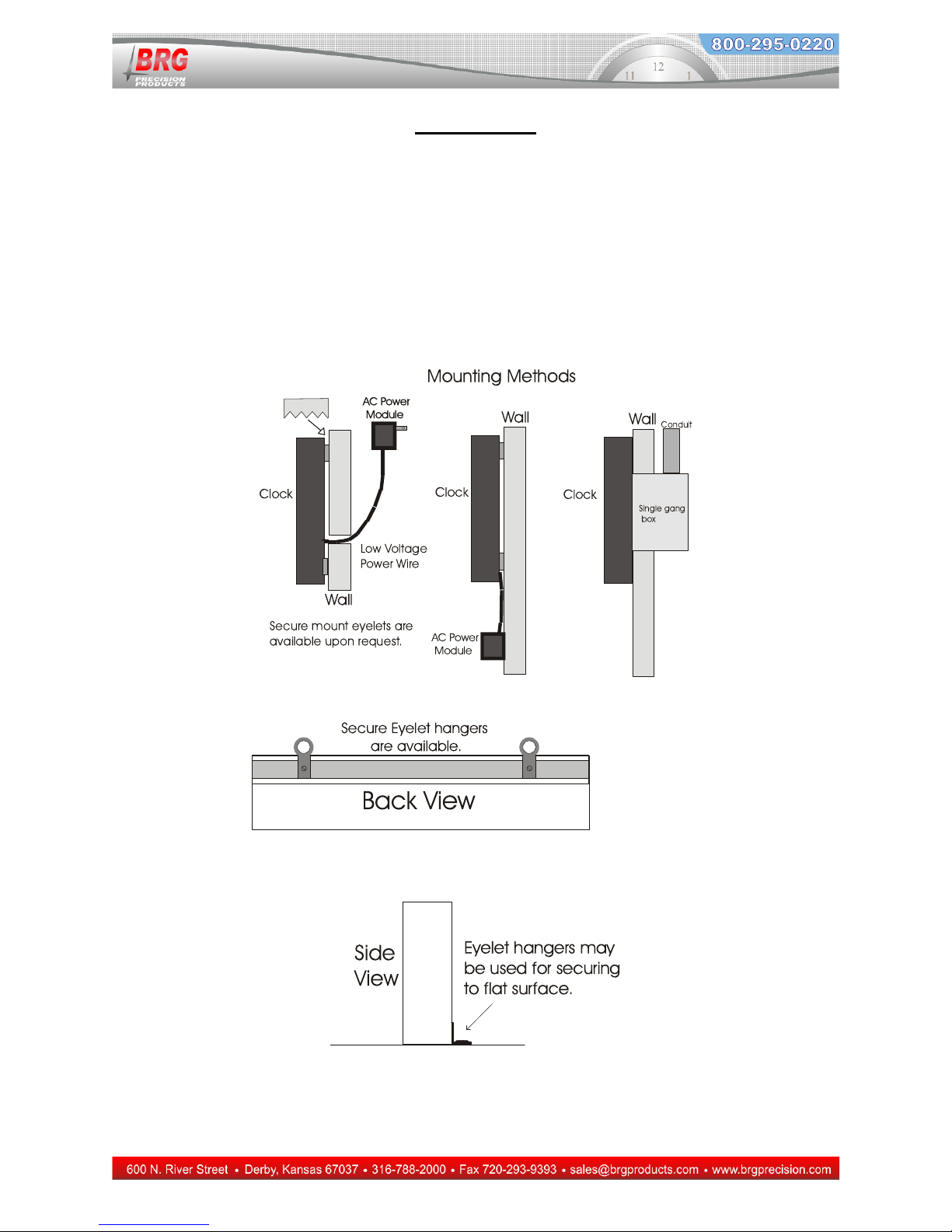
Installation
The digital clocks are constructed using a sturdy aluminum frame with an anti-glare acrylic lens
and ABS back plate. Various mounting methods are available. The standard mounting method
consists of saw tooth hangers located on the back of the clock. Simply drive the appropriate
number of screws into the wall and hang the clock on the screws. Secure eyelet attachments are
also available where a more secure mount is required.
The standard U.S. power configuration consists of a wall mount AC adapter. This adapter drops
the voltage down to a Class 2 voltage. The power wire may be cut, extended and/or and rerouted
through walls as pictured below. Power configurations for other countries may vary.
Sawtooth Hanger

12
Analog Clock Operation
The analog clock is configured using a Windows program. This program is capable of
configuring the time display rules and sending the PC’s time to the clock.
A USB cable is required to connect the clock to the PC. It’s recommended to first connect the
clock to the intended power source for five minutes or more. Then disconnect from the power
source and connect the clock to the PC’s USB port.
Use the PC’s device manager to determine which USB port was assigned to the clock. Install a
USB driver if necessary.
Next, run the clock configuration program.
Select the com port using the drop down box at the bottom of the screen.
If the tie display rules are already configured in the clock and you just need to correct the time,
then clock on the button “Send UTC Time Only”.
If you need to change the display rules, then make changes as needed using drop down boxes on
the right side of the screen. Then click on the button “Send UTC Time With Rules”.
The top text line “PC data send to the clock” display data going from the PC to the clock.
The next text line down “Clock processor data sent to the PC” displays data from the clock to the
PC. If this line is not displayed, then check you com port again or try selecting another com port
from the drop down list.
OCXO Analog Clock Configuration Program Installation
Go to http://www.brgprecision.com/support/software.php and download “Analog OCXO Clock
Control Program”
Unzip the program and run SETUP.EXE to install the program.
The control program is used to control many functions and parameters. The digital clock must
be configured to accept control commands in most cases.
13
The above screen shot shows data that was send to the clock as well as data being send from the
clock to the PC. The time display rules are also displayed.
14
Digital Clock Operation
The BRG Digital Clock uses an L.E.D. display for reliable operation. The clock is protected
against power failures with a rechargeable or Lithium battery. During the absence of power, the
display is blanked to conserve the battery. All operating parameters are stored in non-volatile
memory. The internal clock continues to operate from battery backup. When the A.C. power is
restored, the clock resumes normal operation and display.
If you have any questions or do not understand the operating modes listed below, please
call technical support at 800-295-0220 before making any changes to the clock’s
configuration.
The PM indicator light (located in the upper left corner of the display) is used to indicate PM
hours and sync status. When 12-hour display mode is used, the PM indicator will illuminate
during PM hours. If enabled, the PM indicator will flicker at the top of every minute when the
clock is in sync with a master clock.
Changing the Time :
Press the Up button to advance the time, or the Down button to decrement the time. The longer
you press the button, the faster the clock will move. Some models have these buttons
temporarily disabled.
Configuration Menu:
The Mode, Up, and Down buttons are used to select various operating modes and parameters.
The values of the Mode, Up and Down buttons will change with increasing speed the longer the
buttons are held down. Pressing the buttons quickly will quickly change the value. Some
models have these buttons temporarily disabled.
If the display blinks when the mode button is pressed, mode lockout has been enabled. Hold
down the mode button until the blinking stops (about 5 seconds) then release. A “1” should
appear meaning you have access to the menu system.
The optional infrared or radio remote controls have equivalent buttons for each of the standard
control buttons plus the change starting and ending time or count buttons. Please refer to the
infrared remote instruction section for further explanation.
Press the mode button to switch from real time display to mode selection. Mode number 1 will
display (If the Day/Month displays instead of mode 1, press the mode button again.). Once
Mode 1 displays, use the Up and Down buttons to move to the desired mode.

15
Press the Mode button again to enter a configuration mode. The Up and Down buttons are used
to change modes and values. Press the Mode button again to exit the current mode. The mode
change function will timeout and return to normal time display mode after 60 seconds of
inactivity.
To return to normal time display mode, Press the Timer Control Button, or change the mode
number to zero, or allow the menu system to timeout.

16
Timer Configuration Examples
The following timer configurations are provided as examples of typical elapsed timers. It is, by
no means, intended to be all inclusive. There are many thousands of ways to configure timers.
In timer mode, the Up button becomes Start/Pause/Resume, and the Down button becomes
Stop/Reset. There is an optional timer control line available for specialized timer applications.
Modes 20 and above have two menu levels.
Timer operations are maintained during a loss of power. When the power is restored, the
correct count will display (version 1.77 and later).
Simple Timer Button Control Operation – Mode 32-22
0=disable (default)
1=enable
This mode activates the simple timer button control operation. When enabled, pressing the TC button will cycle
through the display zones. Press the TC button once to select the first zone, causing the zone to blink. Once a zone
is blinking, the Up and Down buttons may be used to change the value of that zone. Pressing and holding the Up or
Down buttons will cause the value to change faster after several seconds. Press the TC button again to move to the
next zone. After the last zone is selected, the display will return to normal operation. The TC button may also be
used to toggle between Up and Down timer operation. During normal display operation, press and hold the TC
button for about 4 seconds. Once zone 1 display blinks, release the TC button to toggle the timer operation. To
determine the timer direction, press the Up button to determine if the timer is in the Up or Down direction. The
simple timer button operation supports display modes 1, 2, 10, 12, 13, 21, 22 and 27. Setting Mode 13=1 will stop a
countdown timer when 0 is reached. Setting Mode32-17=1 will cause a down timer to reverse direction at 0.
Up timer starting at zero. No upper time limit. Display minutes and seconds only on a four
digit display.
1. Mode 23-1=24 – set the display to 24 hour format
2. Mode 7=0:00 – reset to zero
3. Mode 13=0 – allow the timer to pass through the end time, which defaults to 0:00
4. Mode 14=2 – set up timer direction
5. Mode 20-1=12 – configure the display to show minutes and seconds
Hospital Code Blue or Operating Room timer with four digit display. Normally display
real time hours, minutes and seconds. An ordinary light switch with red wall plate is
recommended to control the timer. When the code blue switch is turned on, the display
will immediately switch to up timer mode, reset the timer, start counting up from zero.
Turning the timer switch off will pause the timer for the number of minutes specified in
Mode 32-7. At the conclusion of the pause delay, the timer will return to real time display.
Mode 23-1=24 – set the real time display to 24 hour format (optional)
Mode 32-4=2 – stay in timer mode until pause timeout
Mode 32-5=0 – set timer direction to up direction
Mode 32-6=1 – timer will run as long as timer switch is on
Mode 32-7=30 – stay in timer mode for 30 minutes after timer is stopped, then return to real time display
Mode 36-1=12 – set timer display format to minutes and seconds

17
Hospital Code Blue or Operating Room timer with six digit display. Normally display real
time hours, minutes and seconds. An ordinary light switch with red wall plate is
recommended to control the timer. When the code blue switch is turned on, the display
will immediately switch to up timer mode, reset the timer, start counting up from zero.
Turning the timer switch off will pause the timer for the number of minutes specified in
Mode 32-7. At the conclusion of the pause delay, the timer will return to real time display.
Mode 23-1=24 – set the real time display to 24 hour format (optional)
Mode 32-4=2 – stay in timer mode until pause timeout
Mode 32-5=0 – set timer to up direction
Mode 32-6=1 – The timer will run as long at the Timer Control line is closed. When the timer control line is
opened, the timer will pause for the duration specified by Mode 32-7. Once the pause delay has concluded, the
timer will return to a real time display.
Mode 32-7=10 – stay in timer mode for 10 minutes after timer is stopped, then return to real time display
Mode 36-1=46 – set timer display format to minutes and seconds
Mode 36-2=48 – set timer display format to minutes and seconds
Hospital Code Blue timer with four digit display. Normally display real time hours and
minutes. When the code blue button is pressed or code blue line is turned on, switch to up
timer mode, set the display to minutes and seconds, reset the timer, start counting up from
zero. Pressing the code blue button again will have no effect until the timer is reset back to
real time. Press the reset button once to stop the timer. Pressing the reset button again will
have no effect, unless it is held down for more than five seconds, at which time it will return
to real time display. The display will remain frozen for 30 minutes. After that, it will
automatically return to real time display.
Mode 23-1=24 – set the display to 24 hour format
Mode 13=0 – allow the timer to pass through the end time, which defaults to 0:00
Mode 32-4=2 – stay in timer mode until pause timeout
Mode 32-5=0 – set timer to up direction
Mode 32-6=3 – code blue button will start the timer. Further presses will have no effect until the timer is reset back
to real time.
Mode 32-7=30 – stay in timer mode for 30 minutes after timer is stopped, then return to real time display
Mode 36-1=12 – set timer display format to minutes and seconds
Mode 37-10=3 - holding down the reset button for 5 sec or more returns the timer to real time
Up timer starting at zero. Stop the timer at ten minutes and sound the alert horn for five
seconds. Display hours and minutes on a four digit display with blinking colon while timer
is running.
1. Mode 23-1=24 – display to 24 hour format
2. Mode 5=5 – set alarm duration to 5 seconds
3. Mode 7=0:00 – reset to zero
4. Mode 9=0:10 – end time to 10 minutes
5. Mode 13=1 – stop timer at the end time
6. Mode 14=2 – set up timer direction
7. Mode 20-1=3 – display hours and minutes with blinking colon

18
Up timer starting at zero. Stop the timer at 10 minutes and sound the alert horn for five
seconds. Display hours and minutes on a four digit display with blinking colon while timer
is running.
1. Mode 23-1=24 – display to 24 hour format
2. Mode 5=5 – set alarm duration to 5 seconds
3. Mode 7=0:00 – reset to zero
4. Mode 9=0:10 – end time to 10 minutes
5. Mode 13=1 – stop timer at the end time
6. Mode 14=2 – set up timer direction
7. Mode 20-1=3 – display hours and minutes with blinking colon
Up timer using only the Start button to start, stop and reset the timer. Start at zero and
count up. After the timer has ran for five seconds, allow the Start button to stop the timer.
When the timer is stopped, the start button will reset the timer and start it running again.
Display minutes and seconds only.
1. Mode 13=0 – Do not stop the timer at the end time.
2. Mode 20-1=12 – Display minutes and seconds
3. Mode 37-9=5 – Use the leading edge to start and stop the timer. Wait five seconds before allow the start button
to stop the timer.
4. Mode 37-19=1 – When the timer is stopped, pressing the Start button will reset the timer and start it running.
Elapsed days since last accident or incident on a four digit display. Up timer starting at
12:00, July 10, 2000. This assumes the starting date is older than the current date.
1. Mode 9=12:00 – set starting hour and minutes
2. Mode 32-18=1 – enable auto timer restart after power failure
3. Mode 44-1=07/10 - starting month and day
4. Mode 44-2=2000 - starting year
Elapsed days, hours, minutes and seconds since last accident or incident using a twelve
digit display. Up timer starting at 12:00, July 10, 2000. This assumes the starting date is
older than the current date.
1. Set the current time using the up and/or down buttons
2. Mode 1 – set the current month and day
3. Mode 2 – set the current year
4. Mode 18=3 – number of four digit displays
5. Mode 37-34=21 – display elapsed days on first display (default)
6. Mode 37-35=2 – display hours and minutes (default)
7. Mode 37-36=1 – display seconds on third display
8. Mode 32-18=1 – enable auto timer restart after power failure
9. Mode 44-1=07/10 - starting month and day
10. Mode 44-2=2000 - starting year
11. Mode 9=12:00 – starting hour and minutes
Down timer starting at the 22:00 00, July 4, 2000, and counting down to 00:00 00, January
1, 2001. Display elapsed days, hours, minutes, seconds and hundredths on a twelve digit
display. Flash the display for ten seconds when the timer passes through the end of the

19
year, then reverse timer direction and begin up timer operation. Enable the auto-restart
feature to automatically restart the timer in the event of a power failure.
1. Set the current time (22:00) using the up and down buttons
2. Mode 1=set the current month and day (07/04)
3. Mode 2=set the current year (2000)
4. Mode 5=10 – set alarm duration to 10 seconds – this also controls the length of time to flash the display
5. Mode 9=00:00 – set ending hours and minutes
6. Mode 10=00 – set the end seconds (default)
7. Mode 37-34=21 – display days elapsed on the leftmost four digits (default)
8. Mode 37-35=2 – display hours and minutes on the center four digits (default)
9. Mode 37-36=11 – display seconds and hundredths on the rightmost four digits
10. Mode 26-1=4 – flash the display full on and off at a rate determined by the alarm pulse rate (mode 32-13)
11. Mode 32-13=10 – flash the display at a rate of ten times per second
12. Mode 32-17=1 – reverse timer direction when the end time is reached
13. Mode 32-18=1 – enable auto timer restart after power failure
14. Mode 44-1=00/00 - ending month and day
15. Mode 44-2=2001 - ending year

20
Down timer starting at 10:20 15. Stop at zero and sound the alert horn for 5 seconds.
Display hours, minutes and seconds using an eight digit display.
1. Mode 23-1=24 – display to 24 hour format
2. Mode 5=5 – set alarm duration to 5 seconds
3. Mode 7=10:20 – set Starting hours and minutes
4. Mode 8=15 – set Starting seconds
5. Mode 13=1 – stop at the end time
6. Mode 14=3 – set down timer direction
7. Mode 20-1=2 – display hours and minutes on the leftmost four digits
8. Mode 20-2=1 – display seconds on the rightmost four digits
Down timer starting at 0:30 00. Stop at zero and sound the alert horn for 5 seconds. Blink
the display rapidly one minute before the timer stops. Display hours, minutes and seconds
using an eight digit display.
9. Mode 23-1=24 – display to 24 hour format
10. Mode 5=5 – set alarm duration to 5 seconds
11. Mode 7=10:20 – set Starting hours and minutes
12. Mode 8=15 – set Starting seconds
13. Mode 13=1 – stop at the end time
14. Mode 14=3 – set down timer direction
15. Mode 20-1=2 – display hours and minutes on the leftmost four digits
16. Mode 20-2=1 – display seconds on the rightmost four digits
17. Mode 43-1=3 – Warning time enabled, disable relay output
18. Mode 43-2=0:01 – Set warning time one minute before stop time
19. Mode 43-4=5 – Blink the display for five seconds
20. Mode 43-5=20 – Blink the display twenty times per second
Down timer starting at ten minutes and counting down to zero, then stopping. Flash the
display for five seconds when the timer stops. Display minutes and seconds on a four digit
display.
1. Mode 23-1=24 – display to 24 hour format
2. Mode 5=5 – set alarm duration to 5 seconds – this also controls the length of time to flash the display
3. Mode 7=0:10 – set Starting hours and minutes
4. Mode 13=1 – stop at the end time
5. Mode 14=3 – set down timer direction
6. Mode 20-1=12 – display minutes and seconds
7. Mode 26-1=4 – flash the display full on and off at a rate determined by the alarm pulse rate (mode 32-13)
8. Mode 32-13=10 – flash the display at a rate of ten times per second
Down timer starting at 30 seconds and counting down to zero, then stopping. Close the
alarm relay while the timer is running . Use either the timer control button or the start
button to start timer. Use the Change Start/Change End buttons to change the Starting time
time. Display seconds only, centered on the display.
1. Mode 8=30 – timer Start equals 30 seconds
2. Mode 14=3 – set operating mode to count down timer
3. Mode 32-4=2 – stay in timer mode when the end time is reached
4. Mode 32-5=1 – set code blue timer direction to down timer
5. Mode 32-24=1 – activate relay when timer starts
6. Mode 32-26=1 – enable warning relay
7. Mode 37-12=1- turn off relay when timer stops
8. Mode 37-14=3 – enable Change Start/Change End buttons
Table of contents
Other BRG Clock manuals


