Bricasti Design M21 User manual
M21 Dual Mono Digital to Analog Converter
User Guide
7/18


Unpacking and Inspection
After unpacking the M21 save all packing materials in the event you ever need to ship the unit.
Thoroughly inspect the M21 and packing materials for any signs of damage in shipment. Report any
damage to the carrier at once.
Precautions
The Bricasti Design M21 is a rugged device with extensive electrical protection. However, reasonable
precautions applicable to any piece of audio equipment should be observed.
Always use the correct AC line voltage as set by the manufacturer. Refer to the power requirements
section of the manual and adhere to any power indications on the rear or bottom of the chassis. Using
the incorrect AC line voltage can cause damage to your M21, so please check this carefully before
applying power.
Do not install the M21 in an unventilated rack or directly above any heat-producing equipment like
power amps, tube preamps etc. Maximum ambient operating temperature is 40 C, this would yield an
internal temp of 60 C as indicated on the M21 temp display. Exceeding the maximum ambient
temperature may cause the M21 to enter thermal shutdown and stop processing sound as a safety
precaution, and may cause damage to the internal processors and components.
To prevent fire or shock hazard, do not expose the M21 to rain or moisture.
Notices
In the interest of continued product development, Bricasti Design reserves the right to make improvements
to this manual and the product it describes at any time and without notice.
Copyright 2018
Bricasti Design LTD
2 Shaker Rd J100
Shirley MA 01464 USA
+1 978 425 5199
bricasti.com
All Rights Reserved
This publication is protected by copyright and all rights are reserved.
1

Conformity
EMC / EMI
This equipment has been tested and found to comply within the limits for a Class B digital device, pursuant
to part 15 of the FCC rules. These limits are designed to provide reasonable protection against harmful
interference in residential installations.
Canadian Customers
This Class B digital apparatus complies with Canadian ICES-003.
Cet appareil numerous de la classe B est conforme a la norme NMB-003 du Canada.
Certificate Of Conformity
Bricasti Design, 2 Shaker Rd, Shirley, USA, hereby declares on
its own responsibility the following products:
M21 –Digital to Analog Converter
-that is covered by this certificate and marked with the CE-label
conforms to the following standards:
EN 60065 Safety requirements for mains operated electronic
and related apparatus for household and general
use
EN 55103-1 Product family standard for audio, video,
audiovisual and entertainment lighting control
apparatus for professional use. Part 1: Emission
EN 55103-2 Product family standard for audio, video,
audiovisual and entertainment lighting control
apparatus for professional use. Part 2: Immunity
With reference to the regulations in the following directives:
73/23/EEC, 89/336/EEC
January 2018
Brian S Zolner
President
2

Introduction
This M21 user guide covers theory of design and setup and use. In the future you can always find the latest
version available at our web site www.bricasti.com.
Congratulations on the purchase of your new M21 Dual Mono D/A Converter. We at Bricasti Design have
set out to design the world’s best of analog and digital and to offer the finest products made for the
professional and consumer audio markets.
Product Overview
The M21 has 2 completely isolated fully differential channels, each with its own dedicated linear power
supply, D/A converter, DDS clocking, and analog level control circuitry. This design insures that analog
cross talk is virtually non existent, that the necessary power requirements for each channel are well met and
isolated from each other and the digital processing is isolated, having its own power supply. With our twin
DAC design, the dynamic range for each channel is optimized by using the stereo ADI 1955 D/A converter
in a mono configuration, or an optional Ladder DAC for PCM conversion, clocking is for each channel
done directly at each DAC with a technique called DDS (direct digital synthesis) which takes clock induced
jitter to immeasurable levels, and DSD is converted with our own one bit analog converter.
Build Quality
The M21 is robustly constructed of milled and CNC machined aluminum sections, no typical bent metal
chassis and top cover found on most products. All sections of the construction, the front and rear panels, the
sides and even the bottom and top plates start out as solid blocks of aluminum which are precision
machined to shape, with exact tolerances for a perfect fit. These parts are then anodized and the text and
markings is laser etched for a clean and enduring look.
The Sound
The intention of the M21 is to provide a state of the art, utilizing the best designs and materials that can be
found today. The converter and following analog stages are a very critical part of the digital and analog
audio chain, the sound of the M21 is intended to be transparent and revealing, and fully dynamic. This in
part is made possible by lowering the jitter to extremely low levels, providing a pure digital signal chain
without sample rate converters, superior digital filter design, pure DSD conversion, coupled to a fast
transparent analog signal path with analog level control, discreet analog output section and plenty of good
clean linear power for optimum analog performance.
Many hours of listening were done to tune the M21 to an exacting sound, with all types of music, and with
extensive testing done in the studio and in the home. We hope you find the M21 to be pleasing and
enjoyable to hear and use in the home, or as a precision tool for high level reference monitoring for the
professional.
3

Important Safety Instructions:
Notice!
•Read these instructions.
•Keep these instructions.
•Heed all warnings.
•Follow these instructions.
•Do not use this apparatus near water.
•Clean only with dry cloth.
•Do not block ventilation openings; install
in accordance with manufacturer’s
instructions.
•Do not install near any heat sources such
as radiators, heat registers, stoves, or other
apparatus (including amplifiers, pre amps)
that produce heat.
•Do not defeat the safety purpose of the
polarized or grounded type plug. A
polarized plug has two blades with one
wider than the other. A grounding type
plug has two blades and a third grounding
prong. The wide blade and prong are for
your safety. If the provided plug does not
fit in your outlet, consult an electrician for
replacement of the obsolete outlet.
•Protect power cord from being walked on
or pinched.
•Use only attachments/accessories
specified by the manufacturer.
•Unplug this apparatus during lightning
storms or when unused for long periods of
time.
•Refer all servicing to qualified service
personnel. Service is required when the
apparatus has been damaged in any way,
such as by being dropped, exposed to rain,
liquid being spilled on it, or otherwise
does not operate normally.
Service
•There are no user serviceable parts inside.
•All service must be performed by
qualified personnel.
Warning!
•To reduce the risk of fire or electrical
shock do not expose this equipment to
dripping or splashing water and ensure
that no objects such as vases are placed on
the equipment.
•This apparatus must be earthed.
•This equipment requires the correct AC
line voltage as set by the manufacture
and is not auto sensing or scaling.
•Use a three-wire grounding-type line cord
like the one supplied with this product.
•Be aware that different operating voltages
require the use of different types of line
cords and attachment plugs.
•Check the voltage in your area and use the
correct type. See table below:
Voltage
Line plug standard
110-125V
UL817 and CSA C22.2 no 42
220-230V
CEE 7 page VII, SR section 107-
2-D1/IEC 83 pg C4
240V
BS 1363 of 1984
Specification for 13A fused
plugs and switched and
unswitched outlet plugs
•This equipment should be installed near
the socket outlet and disconnection of the
device should be easily accessible.
•To completely disconnect from AC mains,
disconnect the power supply cord from
the AC receptacle.
•Do not install in a confined space.
•Do not open the unit -risk of electrical
shock inside.
Caution
•You are cautioned that any change or
modification not expressly approved in
this manual could void your authority to
operate this equipment.
4

Design Overview
There are 4 basic internal sections to the M21, the digital input and processing section, and the left and right analog
and PCM DAC sections, and left and right analog line amp with pure DSD conversion and the optional use of
analog level control:
Digital Input Section:
This is the center section of the unit; it provides 6 digital inputs selectable from the front panel. This
section has its own linear power supply and is isolated from the analog sections, providing excellent low
noise performance and helps to eliminates digital noise from entering the analog chain via the power
supplies and ground plane. This section features an Analog Devices Sharc DSP that is used to run the front
panel, general DSP operations of the M21, to control and synchronize the DDS clocking on each channel,
and to provide a selection of our own over sampled anti-aliasing filters.
Analog Output Sections:
On the left and right sides of the rear you will find the analog outputs. Both channels are independently
powered by their own linear power supply insuring clean double regulated low ripple power and isolation
from any digital noise from the digital supply.
There are 2 PCBs in each analog section of the M21, layered on top of the other. The top one provides
pure analog DSD conversion, the ladder DAC and the analog level control yielding a pure analog path
when using the M21 as an analog line stage, the signal then passes to the output buffer and connectors on
the lower board. This analog stage is also used to manage the pure DSD audio path as no digital signal
processing can be done on a true DSD signal; as a result we maintain a true pure DSD converter.
The lower board contains the Sigma Delta PCM dac, clocking and analog output buffers. Each channel’s
digital section has its own Analog Devices 1955 DAC used for PCM conversion, it is coupled with a
dedicated DDS clocking circuit located millimeters away from the DAC, assuring extremely low jitter and
minimal trace length for the clock signal and precise clock synchronization of the left and right boards is
handled by the Sharc DSP on the main digital processing board.
The M21 is a fully differential analog design with fast high slew rate fast settling analog operational amps
used in all audio paths, and a discreet transistor designed output buffer section, for both balanced and
unbalanced, each separately buffered and isolated. The balanced output level will reach a maximum of
+16.5 dbm and the unbalanced of 8dbm with the front panel controlled analog attenuator set at full scale of
+8 dB. With the M21 level control set to 0db the balanced analog out is +13.5db
.
Trigger
On the rear panel the M21 has a stereo connector (Tip/Ring/Sleeve) for the trigger out of M21used to place
and external device like our M28 power amps into standby. Sleeve is connected to chassis ground, the ring
is 5v trigger. Trigger functions can be set in the status menu for trigger in trigger out or trigger remote for
exclusive operation and control from our M20 preamp
5

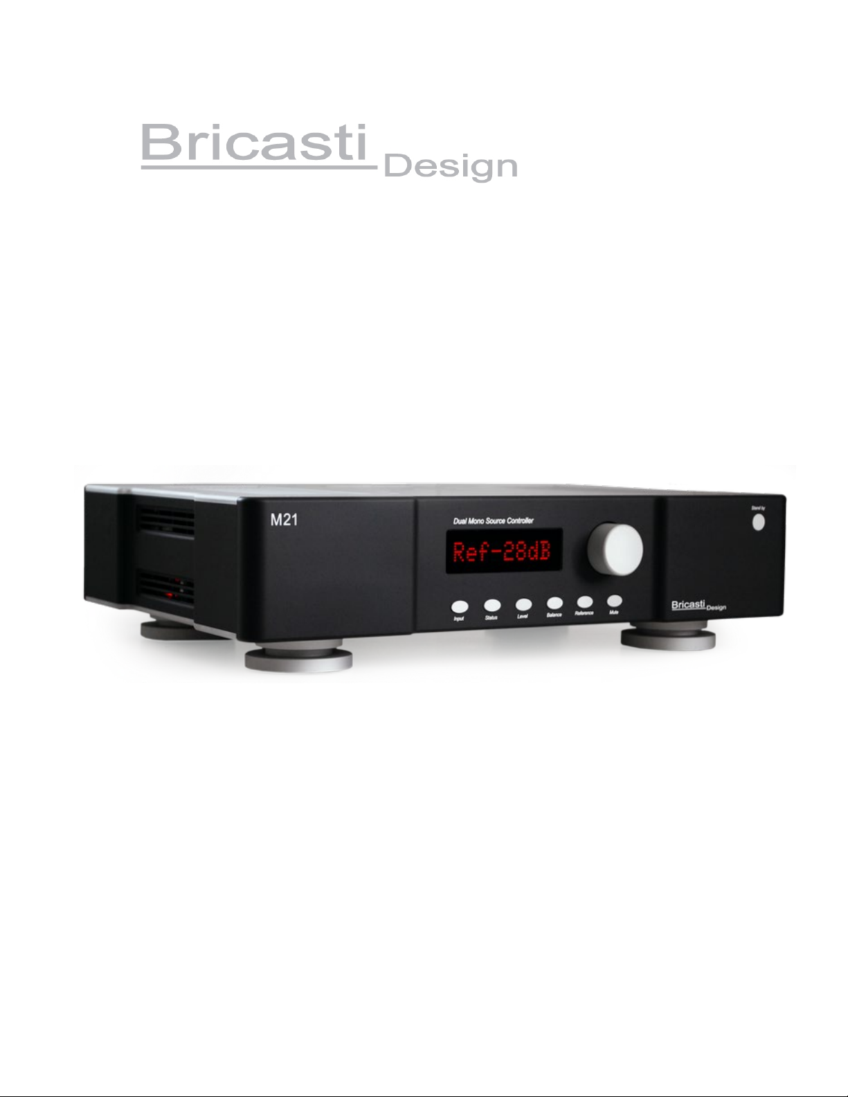
Front Panel Overview
The front panel has a large, simple, easy to read display, an encoder for adjusting and selecting settings, 6
keys that are labeled for their use, and a power stand-by switch that will set the M21 in to low power mode
and mute the analog outputs. There is an IR receiver built in to the left side center of the display for using
the M21 remote controller.
Rear Panel Overview
Looking at the rear you will find on the left and right analog output sections, each with its own balanced
and unbalanced connectors. In the center input section are the 6 digital audio inputs, AES, SPDIF 1 and 2,
Toslink, and USB and RJ 45 network connectors. There is a small jack below the circuit breaker and this is
for a trigger out to remotely place a power amp into like the M28 into standby. The main power on/off
switch are at the rear, note that the front panel standby button is used to set the M21 low power stand by.
Full power on off is done from the rear panel. There are no fuses in the M21 as safety is insured by the use
of a rear panel mounted circuit breaker.
6

Setup and Operation
AC power and the M21
The AC power is connected at the rear of the unit; the filtered AC inlet also has the main power on-off
switch. This filtered inlet helps provide clean AC power to the M21’s power supplies and as well will
prevent any digital noise from the M21s digital processing section from going back out the AC inlet to
contaminate the mains. Take note that the M21 utilizes linear power supplies so care should be taken to use
only the power range indicated on the unit otherwise damage can occur to the power supplies and other
circuits in the M21. Please note and adhere to any voltage indications on the outer box, rear panel or
chassis all of which will indicate how the M21 is set at manufacture.
The main AC power switch is at the rear and the front panel switch is a low power consumption stand by
switch. For complete power on of you must cut power with the rear panel switch or from an external AC
power on off switch that may be used to power other devices in your setup.
Connecting the M21 and power up
When you power up the M21 it has 2 possible states. If it was last used with the level control set 0db it will power
on to the status mode and show what input is selected and sample rate. If the level has been changed to anything
other than 0db it will power up to the level control page and last level set. The default from the factory should be set
to a nominal level of 0db as the M21 is a DAC with the option to use it as a line stage the M21. Connect the M21’s
analog outputs either balanced or unbalance to the appropriate inputs to your pre amp or power amp using high
quality cables and connectors. Care should be taken with levels before playing any music to avoid too high a level
to the power amps and speakers, especially if you will use it to directly drive the power amps as you will have to
reduce the level from the preset of 0db.
Operating the M21
Analog Level Features
The M21 can be used as a pure and direct DAC and used with a preamp or used as a line stage to drive the power
amps directly using its analog level control. When using the M21 as a DAC the front panel level control should be
set to 0db. At this setting the analog signal path will be direct from the chosen DAC (NDSD, Sigma or Ladder) with
a hard wire bypass to the analog output stages, level control is then done with the chosen preamp. When the level is
changed on the front panel away from 0db this will automatically engage the analog level control circuity and allow
for use of the M21 to connect direct to a power amp with no loss bits in the digital domain. Range of control is from
-99db to + 6db in one db steps.
There are 6 front panel keys from left to right: input, status, level, balance, reference and mute.
•Input select
When the M21 first powers on, it will default to LEVEL if the level has been changed or Status menu if the
level was last set to 0db.Pressing the INPUT key will take you to input select mode. Turn the adjust knob
and you will scroll though all inputs, the M21 will auto select them with an audible click of the mute relays.
Inputs are:
•IN1 AES Selects the XLR connector
•IN2 SPDIF Selects the RCA SPDIF connector
•IN3 EIAJ Selects the Toslink connector
•IN4 USB Selects the USB connector.
•IN5 LAN and network streamer
•IN6 SPDIF2 Selects the BNC connector
7

•Status
There are 9 levels in the menu, this menu is for settings that are typically set once and left alone. On first
press it will display input type selected and the running sample rate. For PCM this will range from 44.1k to
384K and DSD will simply display DSD for DSD 64fs or DSD 2 for 128fs.
Listed below are other user parameters in the order they appear in the menu after status.
PCM conversion: this will display and allow for selection of the DAC types for PCM playback, the Sigma
Delta or Ladder DAC.
DSD conversion mode: NDSD DSD is for using our pure 1 bit analog conversion and NDSD PCM is for
using the ADI 1955 sigma delta converter path.
PCM playback oversampling filter: There are 2 choices in the M21, a Linear and Minimum Phase type.
This filter only affects PCM playback and not DSD. See more about DSD in the later section about DSD.
Internal temperature monitor: there are no adjustments as this is just a monitor of internal temps.
Display Intensity: set in 3 levels and set it to a sleep or off mode. use the knob to select the brightness of
the display, selecting OFF will shut the display off after a 20 sec time out, leaving one LED dimly lit.
Pressing any front panel key will wake up the display so you can make adjustments to the M21, and then
after a short period of no use, it will go to off mode again.
Trigger functions: Sets the M21 trigger commands. CtlTRIGO sets trigger out, CtlTRIGI for trigger in,
CtlREMOTE for exclusive use with the M20 preamp control commands.
Phase Invert: The M21 is absolute phase meaning that it does not invert the phase. With this adjustment
you can invert the phase in the digital domain of PCM playback signal; there is no phase inversion of the
analog path in the M21 so no inversion of the DSD is possible.
Version: the current software version installed in the M21.
•Level
The M21 has an analog level control, it will affect both the balanced and unbalanced outputs exactly the
same and insures perfect channel balance at all gain settings. Operation is simple: press Level and it will
display the level in dB. Normally this will be set to the last level set. Turn the knob and you can seamlessly
adjust level in one dB steps. When setting the M21 to 0db the M21 is placed in hard wire bypass mode
allowing the M21 to be used as a direct pure DAC. Pressing the Level key a second time will set the output
to MUTE, pressing again will un-mute. Upon power up, if the M21 will power back at the last used level
setting.Range is -90 to 0db and 0 to +6
•Balance/Standby
The M21 has an analog balance control, it will affect both the balanced and unbalanced outputs exactly the
same. Press the balance button and use the adjust knob to change the balance in .5 dB steps. The display
will show the amount of attenuation of the left or the right channel to change the relative balance of the
channels. As an additional feature pressing a long hold on the balance control will remotely set the M21
into stand by. Pressing a long hold press will return to power on mode.
•Reference
This is a user memory for a reference level setting. Press and hold (long press) the reference button and it
will memorize the current operating level. A quick press will recall this setting. This is useful for a
favorite listening level or as a way to use the analog inputs as a home theater and memorize the analog gain
settings for later recall.
•Mute
Pressing this key will mute the analog output with a fast fade out and fade in using the M21 analog level
control. Mute can also be engaged by pressing the level key a second time.
8

USB Features
On the rear panel you will find the USB 2 type interface and it is based on the latest generation of asynchronous
design and supports sample rates up to 384k/24 bit. For superior noise performance the interface is electrically
isolated from the host computer, eliminating any grounding or power induced noise issues that could be transmitted
to the M21 from the computer. No driver is needed for Macs or Linux but for PC use a driver is necessary and the
latest version for Win 8 and 10 support can be acquired from our website in downloads section.
Network Interface Features
On the rear panel you will find the RJ 45 Ethernet connector. This connector is for using the M21 as a DNLA
compatible network player. When The M21 is connected to a network router it will appear as a player in the media
player and server that it’s connected to as a device to “play to” from the server. This server can be a PC or even an
android type UNpN or DNLA network player installed on your pad or phone. The M21 player is also known as a
“renderer” or “streamer”. To set this up your server application must have network sharing functions enabled and
there is no need to down sample and should be set to play native sample rates. The M21’s player supports sample
rates up to 384k PCM and DSD128 as DoP.
DSD playback and the M21
DSD playback with the M21 is done via DoP and as such can be read with any input, but most common is the USB.
DoP is DSD over PCM and for DSD 64 is the 1 data bit stream embedded in a 176.4k 16 bit PCM data stream with
the extra 8 bits out of the 24 bits used for identifying that it is DSD not PCM. This is true DSD and not PCM
conversion. When using a computer audio setup, the media player should be set to send out the DSD as DoP, the
M21 will see that as 176.4k pcm for DSD 64fs or 352.8k for DSD 128fs, read the data header and see that it is
actually DSD and unpack the data in our digital signal processor as the original DSD data, and send it out to the
DAC for conversion to analog.
The M21 features 3 digital audio conversion paths, 2 for PCM which utilizes a sigma delta or ladder dac types, and
for DSD is a true one bit modulator of our own design and unique to the industry. This DSD conversion is done on
the M21s analog level boards and is a true 1 bit analog converter followed by an analog post noise filter. The result
is a true a pure DSD play back unlike any other converter in the market. It is recommended that this feature be
selected in the status menu labeled NDSD. The other choice is DSD PCM and this will set the path to use the ADI
1955 as the multi-bit converter which will impart a different sound character than the native one.
To use it all you need is DFF or DSF files, set the media player to play the files as DoP, and the M21 will play them.
When DSD is received for playback the status and filter displays will read DSD, and when it next plays a PCM file
it will revert to your last used PCM filter and display will update accordingly. Playback is seamless as any other
PCM sample rate change. If the M21 does not display DSD when playing back DSD source then check your media
player settings for DSD and insure that it is being sent as DoP.
When using USB and the LAN the M21 supports both DSD 64, one bit at 64 times 44.1k sample rate, and DSD 128
or double that rate. DSD 64 is the SACD standard and 99% of all content is released and mastered at this rate.
There is some content appearing that is DSD 128 or 2x the rate but for the most part you will find DSD 64 as the
standard.
When selecting NDSD DSD setting, the DSD post noise filtering is done in the analog domain so there are no DSD
filter settings. An artifact of DSD processing is the buildup of ultrasonic noise and with DSD 64; this noise starts at
24 kHz and rises to peak level at -50 dB at 50k and beyond. In the M21 set to NDSD DSD this filter is implemented
with a simple low order low pass analog filter for the very best sonic performance.
A great source for DSD downloads is: www.channelclassics.com
9
Digital Oversampling Filters for PCM conversion
There are 2 types of filters that can be chosen for PCM playback, a Minimum Phase and Linear Phase. For example
at 44.1k decoding these are 20kHz bandwidth, stop-band at Nyquist frequency with low ripple and high attenuation
filters. You will find despite having similar specs, that they both have very unique and different sound
characteristics, and you may find one more suitable for different kinds of music than others as well.
The M21 uses delta sigma 8 x oversampling conversion so it is not recommended to “up-sample” the digital audio
that is being sent to the M21 within a media player option. Defeat all up-sampling features in your media player or
CD transport. Up-sampling the data before the M21 will yield poor results and always use the original source audio
bit and sample rates, so for example if the source is 44.1k then have the media player send this data unprocessed to
the M21and let the M21 reconstruct the data correctly.
The M21 Remote
The M21 is supplied with a dedicated IR (infrared) remote control. This is a simple remote and allows for most
commonly used functions of the M21 to be controlled remotely from your listening position. This is an IR device so
it is important that line of sight to the M21 front panel where the IR receiver is mounted is maintained. With any
device like this there are distance and parallax limitations. For example if you are far off to one side, too high or
low, or too far away then the remote may not work correctly and there will be errors in the light emitted pulses
causing missed or wrong data. Be sure to be within reasonable distance, about 25’ and within a + or - 45 degree
angle from the front panel. Operation has the same paradigm as the front panel control, with all the same labeled
functions for both.
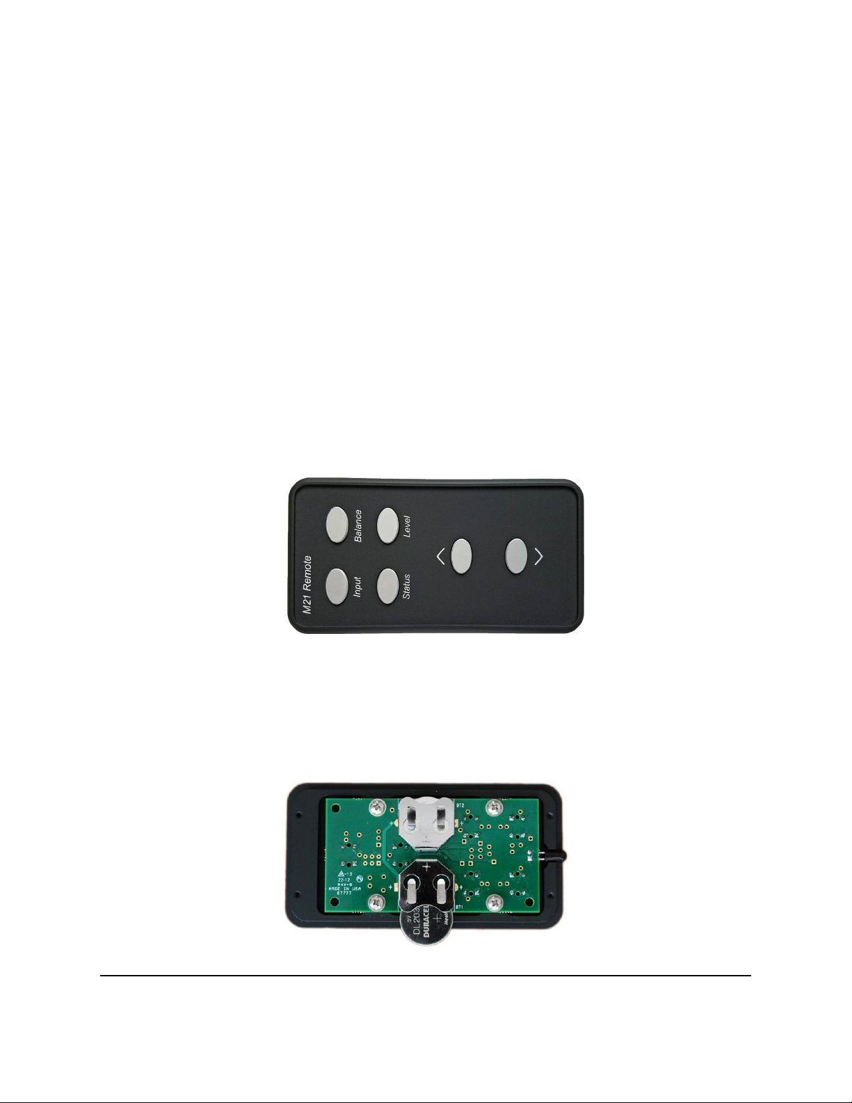
Replacing the remote batteries
The remote comes complete with batteries installed but in the event you need to replace them here simply open the
casing of the remote with a 5/64” hex key and remove and replace the batteries noting the polarity marking on the
battery holders that the + side of that battery is face up, - side down or in contact with the PCB. Reassemble taking
care not to over tighten the 4 small socket cap screws that hold the casing together as they are small and could easily
strip out the threads of aluminum housing of the remote casing.
Inside the remote with one partially inserted battery showing correct polarity
10

Technical Specifications
Digital Inputs
Connectors: XLR: AES/EBU 24 bit Single Wire
RCA & BNC: SPDIF
Optical: Toslink 44.1- 96k
USB: USB 2
RJ45: Ethernet
Sample Rates AES, SPDIF: 44.1 kHz, to, 192khz , DSD 64fs as DoP
Sample Rates USB: 44.1 kHz, to, 384kHz, DSD 64fs, 128Fs as DoP
Sample Rates Ethernet: 44.1 kHz, to, 384kHz, DSD 64fs,128Fs as DoP
Jitter: 8 psec @ 48k / 6psec @ 96k
Balanced Analog Outputs
Connectors: XLR balanced (pin 2 hot)
Impedance: 40 ohm
Output: @ 0 db front panel +13.5 dbm 3.5db RMS ( bypass mode)
D/A Conversion: PCM 24 bit delta sigma 8x oversampling
20bit ladder dac for PCM conversion
NDSD pure 1 bit conversion for DSD
Frequency Response @44.1k: 10 hz- 20 kHz +0dB, -.2 dB
Dynamic Range: >120dB A-Weighted
THD+N @ 1k: .0008%@ 0dBfs / .0004% @-30dbfs
Unbalanced Analog Outputs
Connectors: RCA
Impedance: 40 ohm
Output level: @ 0 db front panel = +4db 2V rms
Frequency Response @ 44.1k: 10 hz- 20 kHz -.2 dB
Dynamic Range: >120dB A-Weighted
THD+N @ 1k: .0008% @ 0dbfs / .0004% @-30dbfs
General Specifications
EMC
Complies with: EN 55103-1 and EN 55103-2 FCC part 15, Class B
RoHS
Complies with: EU RoHS Directive 2002/95/EC
Safety
Certified to: IEC 60065, EN 55103-2
Environment
Operating Temperature: 32 F to 105 F (0 C to 40 C)
Storage Temperature: -22 f to 167 F (-30 C to 70 C
General
Finish: Anodized Aluminum
Dimensions: 17” x 12“ x 4.5”
Weight: 15 lbs
Shipping Weight: 18 lbs
Shipping Dimensions: 22”x 17”x 7”
Mains Voltage: 100, 120, 220, 240 VAC, 50 Hz – 60 Hz factory set
Trigger in/out: TRS connector for 5V external trigger on ring.
Power consumption: 30 Watts
Warranty parts and labor: 2 years non transferable
11

Copyright 09/2016- Bricasti Design Ltd.-2 Shaker Rd,- Shirley, MA 01464 USA
Table of contents
Other Bricasti Design Media Converter manuals


