Brickom Professional Outdoor Bullet Series Instructions for use

Hardware User’s Manual
Megapixel Day & Night
Outdoor Bullet Network Camera
Quality Service Group
Professional Outdoor Bullet Series

1
Review History:
1. Separate User Manual into HW and SW.
2. Merge OB-100A V2 series /OB-130N-series into this User Manual.
3. Add OB-500A Series /OB-300N Series into the User Manual.
4. Clarify the OB series Reset button and WPS button.
5. HW add one function for TV out Connector.
6. Modify I/O Terminal Block definition.
7. Add OB-200Np-LR Series into the User Manual
8. Update OB-P series V6 version
9. Add WOB Series and GOB Series into the User Manual
Product name:
Network Camera (Outdoor Bullet series)
Release Date:
2015/09
Manual Revision:
V4.0
Web site:
www.brickcom.com
Email:
support@brickcom.com
© 2015 Brickcom Corporation. All Rights Reserved

2
Table of Contents
Before You Use This Product .......................................................................................3
Regulatory Information .................................................................................................4
Chapter 1 - Package Contents......................................................................................5
Chapter 2 - Outdoor Bullet Network Camera Overview..............................................7
Chapter 3 - Device Appearance Description ...............................................................8
Chapter 4 - Installation................................................................................................14
4.1 Hardware Installation.......................................................................................14
4.2 Camera Connection.........................................................................................19
4.3 System Requirements .....................................................................................21
4.4 Software Installation ........................................................................................22
4.4.1 EasyConfig............................................................................................ 30

3
Before You Use This Product
In many countries, there are laws prohibiting or restricting the use of surveillance
devices. This Network Camera is a high-performance, web-ready camera which can be
part of a flexible surveillance system. It is the user’s responsibility to ensure that the
operation of this camera is legal before installing this unit for its intended use.
Upon opening the product’s package, verify that all the accessories listed on the
“Package Contents” are included. Before installing the Network Camera, read the
warnings in the “Quick Installation Guide” to avoid misuse. When installing the Network
Camera, carefully read and follow the instructions in the “Installation” chapters to avoid
damages due to faulty assembly or installation.

4
Regulatory Information
Federal Communication Commission Interference Statement
This equipment has been tested and found to comply with the limits for a Class B digital
device, pursuant to Part 15 of the FCC Rules. These limits are designed to provide
reasonable protection against harmful interference in a residential installation. This
equipment generates uses and can radiate radio frequency energy and, if not installed
and used in accordance with the instructions, may cause harmful interference to radio
communications. However, there is no guarantee that interference will not occur in a
particular installation. If this equipment does cause harmful interference to radio or
television reception, which can be determined by turning the equipment off and on, the
user is encouraged to try to correct the interference by one of the following measures:
- Reorient or relocate the receiving antenna.
- Increase the separation between the equipment and receiver.
- Connect the equipment into an outlet on a circuit different from that to which the
receiver is connected.
- Consult the dealer or an experienced radio/TV technician for help.
FCC Caution: Any changes or modifications not expressly approved by the party
responsible for compliance could void the user's authority to operate this equipment.
This device complies with Part 15 of the FCC Rules. Operation is subject to the following
two conditions: (1) This device may not cause harmful interference, and (2) this device
must accept any interference received, including interference that may cause undesired
operation.
IMPORTANT NOTE:
FCC Radiation Exposure Statement:
This equipment complies with FCC radiation exposure limits set forth for an
uncontrolled environment. This equipment should be installed and operated with
minimum distance 20cm between the radiator & your body.
This transmitter must not be co-located or operating in conjunction with any other
antenna or transmitter.
The availability of some specific channels and/or operational frequency bands are
country dependent and are firmware programmed at the factory to match the
intended destination. The firmware setting is not accessible by the end user.

5
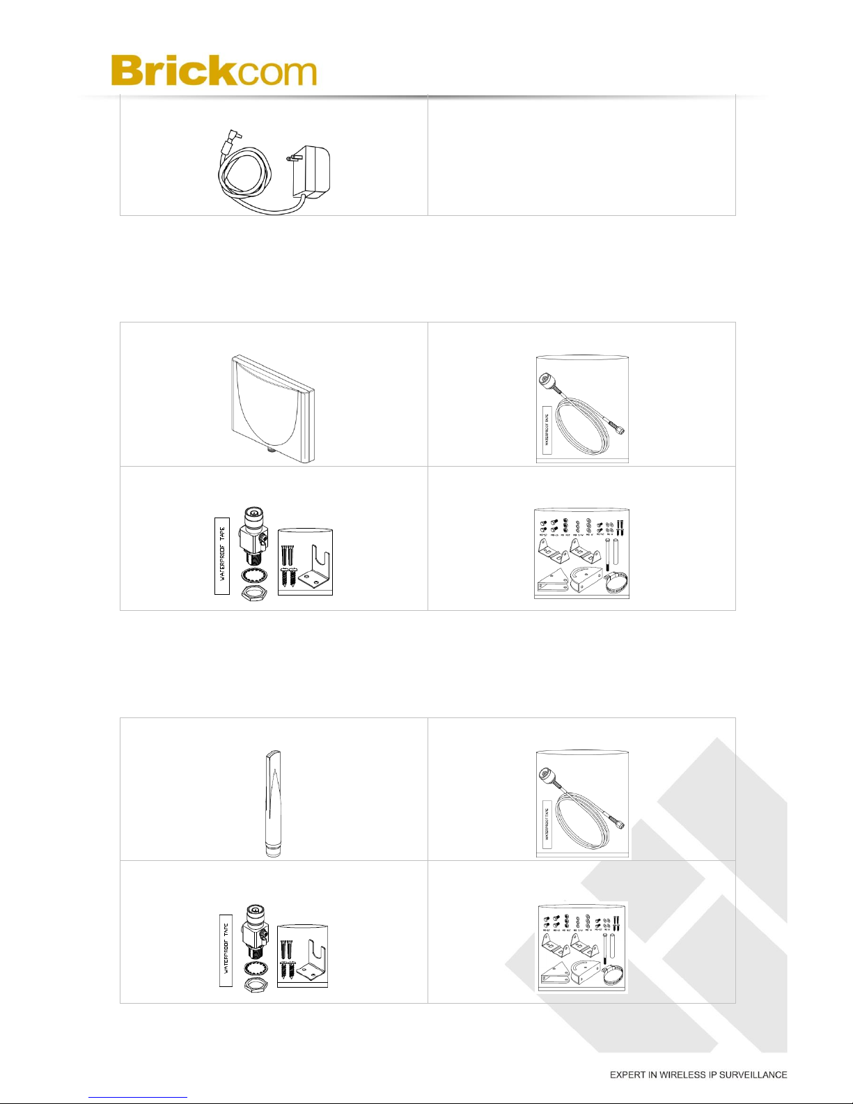
Chapter 1 - Package Contents
Please check to make sure the product package contains all the accessories listed
below.
A. Camera Package Contents
a. Network Camera
b. Shielding Cover
c. Screw bag
d. Product CD
e. Warranty Card / Easy Installation
Guide
f. Water Proof Connectors
g. Dry Bag
h. High Power POE (Optional)
i. Bracket (Optional)
j. Bracket Assembly Plate (Optional)
k. Wi-Fi Dual Band Antenna package
(Optional)
l. 3G Antenna package (Optional)
OB-p Series
OB-p-LR Series
6
m. Power adapter (Non LR-Series)
B. Wi-Fi Antenna Package contents (Optional for WOB-P Series)
Refer to the installation guide included in the package when installing the
Wi-Fi antenna
a. Wi-Fi Dual Band Antenna
b. Extension Cable
c. Surge Arrestor Kit
d. Mount Kit
C. 3G / 4G LTE Antenna Package contents (Optional for GOB-P series)
Refer to the installation guide included in the package when installing the
3G antenna
a. 3G / 4G LTE Antenna
b. Extension Cable
c. Surge Arrestor Kit
d. Mount Kit

7
Chapter 2 - Outdoor Bullet Network Camera
Overview
The Brickcom Outdoor Bullet SERIES is an outdoor bullet network camera. It adopts a
megapixel sensor which allows the camera to deliver extremely clear and detailed
images that CCTV cameras cannot offer. To optimize use of the megapixel resolution,
the Outdoor Bullet SERIES uses efficient H.264/ MJPEG/ MPEG-4 codec compression
to deliver dual configurable video streams simultaneously at up to 30 fps. These
features make this series the perfect outdoor camera for neighborhood, school campus,
and parking lot surveillance.
The Outdoor Bullet SERIES has many user friendly features, such as the Smart Focus
capability which allows users to configure settings for excellent image quality without
difficult procedures. Support for Power over Ethernet enables the camera to use the
same cable for power and data transmission, eliminating the need to install an external
power supply.
Installation for the WOB/GOB Series models is not restricted by location or landforms.
The cameras offer various wireless options that make connecting to networks easier by
adopting the technology of IEEE 802.11 a/b/g/n and 3G SIM module. The wireless
Bullet Cameras can be set within any wireless or 3G signal coverage areas. Users do
not have to worry about the data connection failing because each camera is equipped
with a SD/SDHC memory card slot for local storage.
With an IP67 certified outdoor enclosure, the Outdoor Bullet SERIES is not only weather
proof, but also dust and rust resistant. By utilizing a built-in industrial fan and heater, it
can perform well in extreme environments.
8
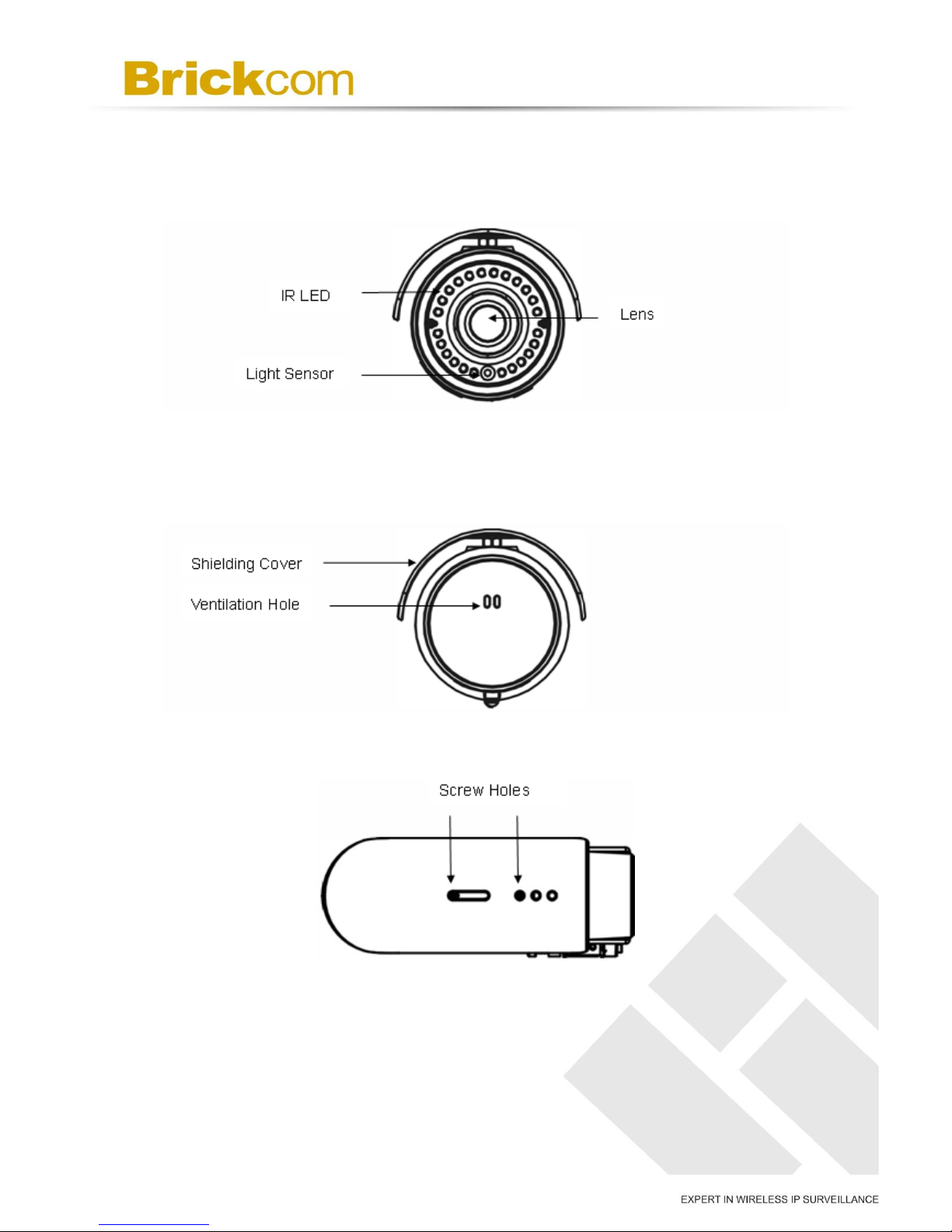
Chapter 3 - Device Appearance Description
< Front Panel >
< Rear Panel >
< Top >
< Bottom >

9
< Side >
**3G SIM Card Slot only apply for GOB & WOB series**
< OB-p-LR series >
Micro-SD/SDHC Card Slot
3G SIM Card Slot
Micro-SD/SDHC/SDXC Card Slot
10
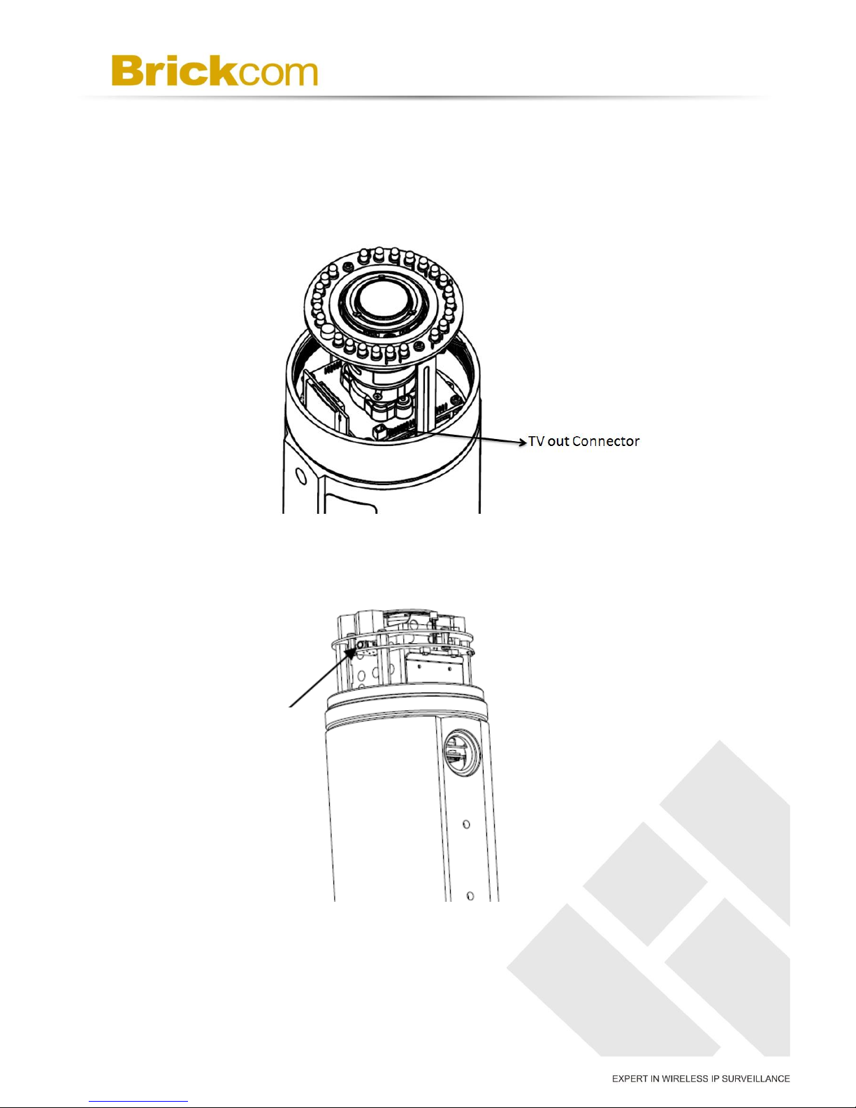
<Inside> TV out Connector
***This function only apply below models.***
OB-502A Series/OB-500A Series and OB-302N Series/OB-300NSeries
< OB-p-LR series >
TV out Connector
11
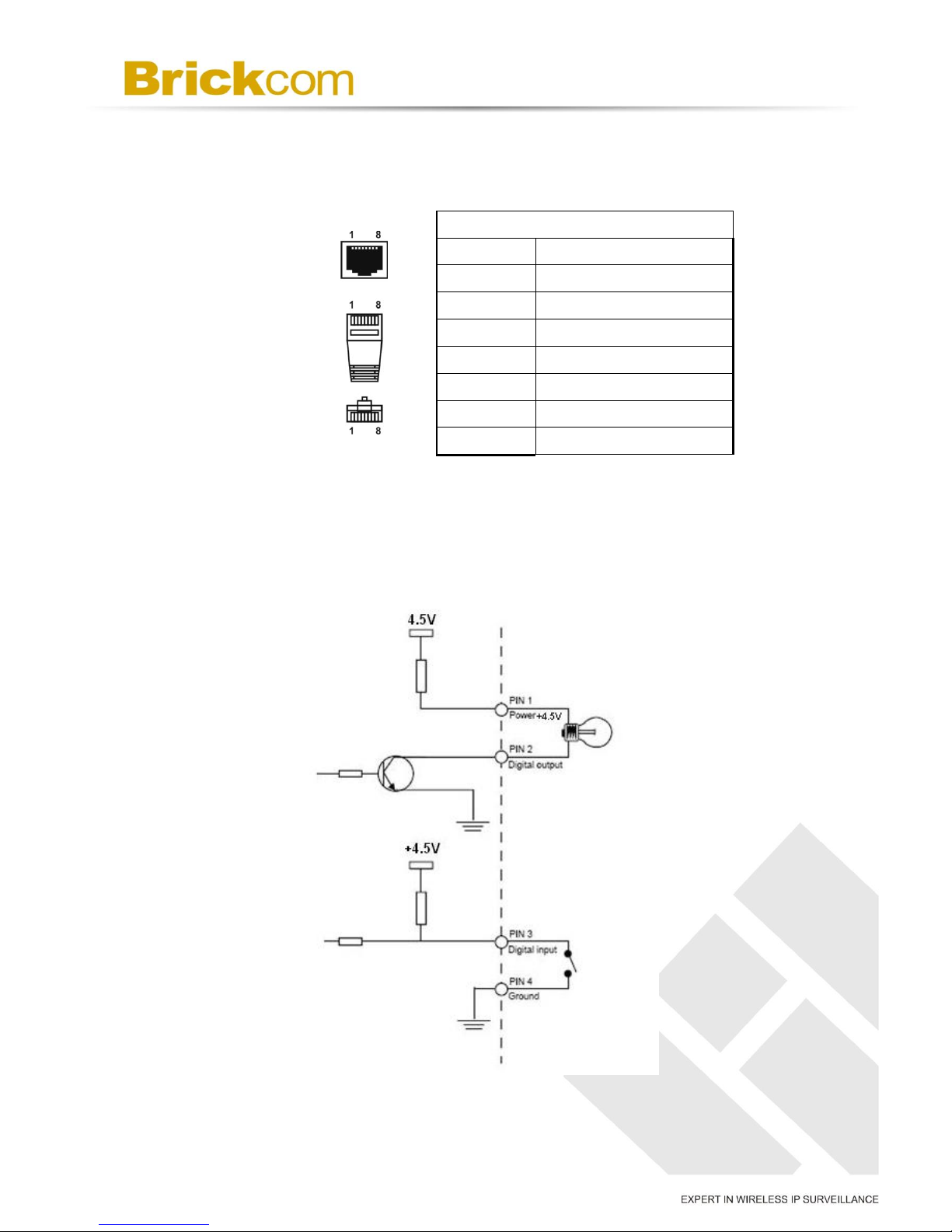
< Extension I/O Terminal Block >
The Network Camera provides an extension I/O terminal block which is used to connect
the camera with external input/output devices. The pin definitions are listed as below.
Pin No.
Pin 1
Power +4.5V / 12V*
Pin 2
Digital Output
Pin 3
Digital Input
Pin 4
Ground
Pin 5
RS-485-
Pin 6
RS-485+
Pin 7
Audio-in
Pin 8
Audio-out
* V5 & V6 Series Supported*V5&V6 (WDRPro & Star & StarPlus) Series Supported
DI/DO Diagram >
OB-100Ap Series and OB-130N Series
/ +12V*
/ +12V*
/ + 12V*

12
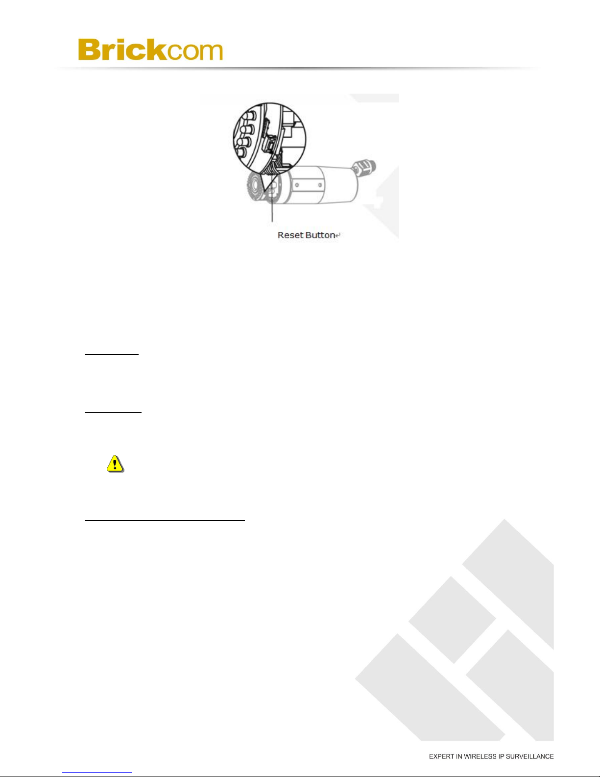
< Reset button >
OB-502A Series and OB-302N Series
Reset Button and WPS button
**WPS Button only applies for WOB-502A Series/WOB-500Ap Series /WOB-302Np
Series/WOB-300Np Series**
<Noted> WPS button for quickly link to WiFi.
Reset Button
13
< Hardware Reset >
The Reset Button can be used to reboot the camera or restore it to factory default
settings. If the camera experiences a problem, rebooting the camera may correct the
problem. If the problem remains, please restore the camera to factory default settings
and reinstall the software.
To Reboot
Press and hold the Reset Button for one second using a paper clip or thin object. Wait
for the camera to reboot.
To Restore
Press and hold the Reset Button for ten seconds until the LED light turns off. When
successful restored, the LED will be blue during normal operation.
NOTE - By restoring the camera, all settings will be restored to the factory
default settings.
Micro-SD/SDHC Card Capacity
The network camera is compatible with Micro-SD/SDHC (Maximum 32GB) cards.
(*) These are optional features. Please refer to the Product List for the full list of
optional features that are available for this product.

14
Chapter 4 - Installation
4.1 Hardware Installation
WARNING - Do not mount the camera on a soft material. The camera
may fall and be damaged.
A. Micro-SD/SDHC Card and 3G SIM Card(GOB series) Installation
a. Remove the Lens cover from the Bullet Camera.
b. Inset the Micro SD/SDHC card and 3G SIM card(*) into their respective
slots.
c. Place a dry bag onto the camera device.
d. Reattach the Lens cover and secure the cover to the top of the camera
device using two screws.
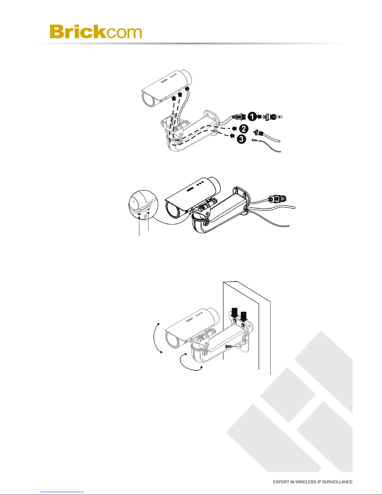
B.Wall Installation Using the Optional Bracket
a. Using the Bracket plate as a guide, drill three holes into the wall and
hammer the supplied plastic anchors into the three holes. Use a

15
screwdriver and the supplied screws to secure the plate to the wall.
b. Attach the Bracket Assembly Plate to the bottom of the camera using
two screws.
c. (1) Use the two supplied screws to secure the bracket to the side of the
camera. (2) Push back the spring on the mortise lock and hook the
camera and attached bracket onto the groove of the wall mount bracket
as shown in the diagram.
d. Connect (1) the POE cable; (2) DIDO, Audio In/Out, RS485 cable; and
16
(3) Antenna cable with the camera (only for GOB series). Refer to
step 3 for more details installation information.
e. Secure the two screws on the wall mount bracket.
f. Place the wall mount bracket on the plate and attach it using the
supplied screws. Adjust the angle of the wall mount bracket towards
the area to be monitored.
B. DIDO, Audio In/Out, RS485, and Antenna Connection(GOB & WOB
series only)

17
a. PoE Connection
For the Power over Ethernet connection, construct the PoE cable using
the pin definitions of the RJ45 connector below and refer to step 5 for
instructions on how to install the Water Proof Connector. Once the
PoE cable has been constructed using the waterproof connector, pass
the RJ-45 cable from the camera through the bracket and connect it to
the PoE cable.
RJ45 Connector 1
Pin No.
Function
Pin 1
Transmit Out+ (Tx+)
Pin 2
Transmit Out- (Tx-)
Pin 3
Receive In+ (Rx+)
Pin 4
DC 48V
Pin 5
DC 48V
Pin 6
Receive In- (Rx-)
Pin 7
48V_GND
Pin 8
48V_GND
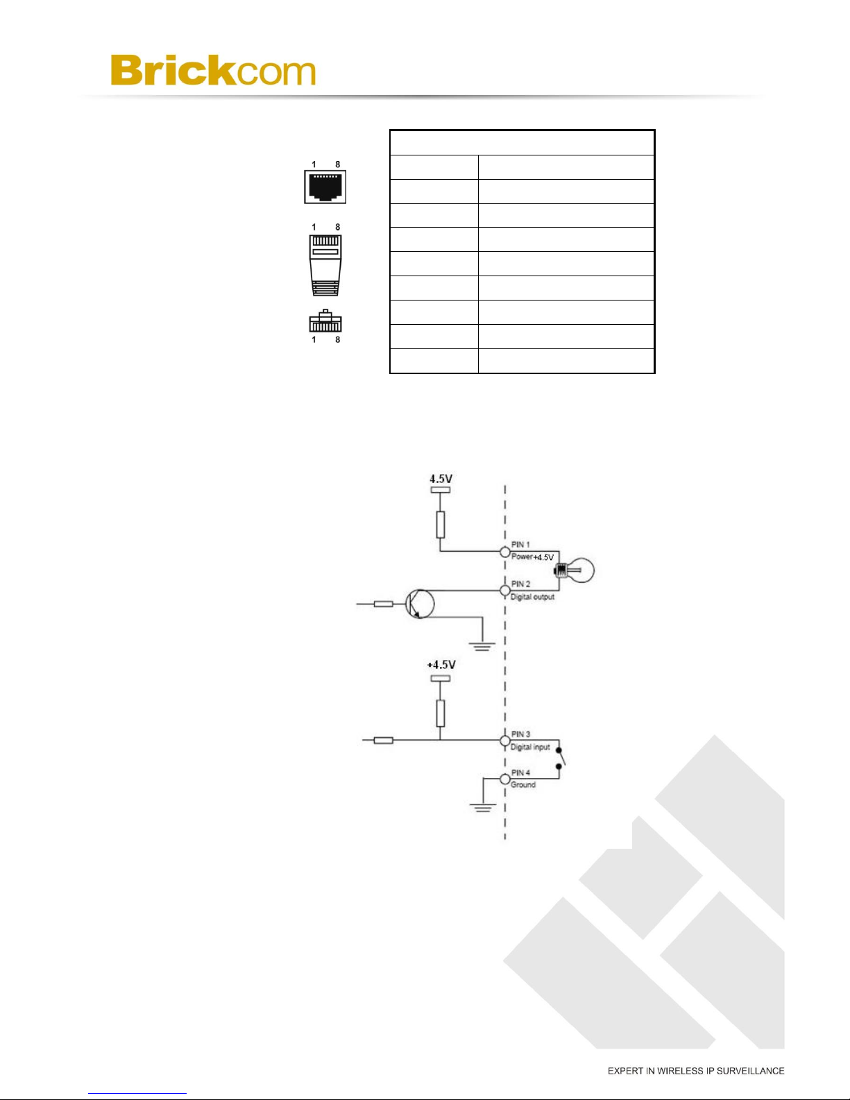
b. DIDO, Audio In/Out, RS485 Cable Connection
For the DIDO, Audio In/Out and RS485 cable connection, construct an
Ethernet cable using the pin definitions of the RJ-45 connector below
and refer to step 4 for instructions on how to install the Water Proof
Connector. Once the Ethernet cable has been constructed using the
waterproof connector, pass the cable through the bracket and connect
18
it to the RJ-45 connector at the bottom of the camera.
RJ45 Connector 2
Pin No.
Function
Pin 1
Power +4.5V / 12V*
Pin 2
Digital Output
Pin 3
Digital Input
Pin 4
Ground
Pin 5
RS-485-
Pin 6
RS-485+
Pin 7
Audio-in
Pin 8
Audio-out
*V5&V6 (WDRPro & Star & StarPlus) Series Supported
DIDO Diagram
c. WiFi or 3G Antenna Extension Cable Connection(GOB & WOB
series only)
Pass the Antenna extension cable (1) through and bracket and connect
it to the Antenna connector (2) at the bottom of the camera.
/ +12V*
/ + 12V*
/ + 12V*

19
4.2 Camera Connection
The Outdoor Bullet Series is PoE compliant, so there are two options for
connecting the camera to a power and Ethernet source. The camera can
either be connected to a PoE-enabled switch or a non-PoE switch.
a. If using a PoE-enabled switch: (OB-X00Np-LR series require 802.3at
PoE)
i. Use a single Ethernet cable to connect the camera to the PoE-enabled
switch.
b. If using a non-PoE switch: (OB-X00Np-LR series require 802.3at PoE)
i. Use a standard RJ-45 cable to connect the camera to a PoE Injector.
ii. Use a standard RJ-45 cable to connect the PoE Injector to the non-PoE
switch.
c. Use a standard power cable to connect the PoE Injector to a power outlet.If
Table of contents


