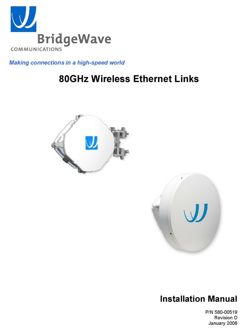
BridgeWave AR60X User manual

Makingconnectionsinahighspeedworld
AR60XWirelessEthernetLinks
InstallationManual
P/N58000517
RevisionB
January2008

AR60XInstallationManual
58000517,revB ii
CopyrightNotice&Disclaimer
Copyright©2004 2008BridgeWaveCommunications.Allrightsreserved.
PrintedintheUSA
Noportionofthispublicationmaybereproduced,copied,ordistributedwithoutthewritten
consentofBridgeWaveCommunications.BridgeWavereservestherighttoupdateorchangethe
materialinthispublicationatanytimewithoutnotice.BridgeWavehasmadeeveryeffortto
ensurethattheinformationandtheinstructionscontainedinthepublicationareadequateandis
notresponsibleforanyerrorsoromissionsduetotyping,printing,oreditingofthisdocument.
PurchasersofBridgeWaveproductsshouldmaketheirownevaluationtodeterminethe
suitabilityofeachsuchproductfortheirspecificapplication.BridgeWave’sobligations
regardingtheuseorapplicationofitsproductsshallbelimitedtothosecommitmentstothe
purchasersetforthinitsStandardTermsandConditionsofSaleforadeliveredproduct.
Thispublicationhasbeenpreparedforprofessionalandproperlytrainedpersonnel,andthe
customerassumesfullresponsibilitywhenusingtheinformationherein.
ExportControl
AllBridgeWaveradioproductsarerestrictedcommoditiesthatfallunderECCN5A002ofthe
DepartmentofCommerce.Theseproductsare"ENCrestricted"undersection740.17(b)(2)of
theExportAdministrationRegulations(EAR).BridgeWaveproductsmayonlybeexported,re
exported,transferred,orretransferredinaccordancewithExportAdministrationRegulations.
DiversioncontrarytoU.S.lawisexpresslyprohibited.
ProductCompatibility
Whileeveryefforthasbeenmadetoverifyoperationofthisproductwithmanydifferent
communicationsproductsandnetworks,BridgeWavemakesnoclaimofcompatibilitybetween
itsproductsandothervendors’equipment.Itisassumedthatusershavethoroughlyevaluated
thisproduct’sperformanceinthecommunicationsenvironmentinwhichitwillbeused.

AR60XInstallationManual
iii 58000517,revB
Safety
CAUTION,WARNING,andDANGERstatementshavebeenstrategicallyplacedinthetextto
alertpersonnelofpossiblehazards.Thesestatementsmustbecloselyobserved.
Thefollowinggeneralsafetyprecautionsmustbeobservedduringallphasesofoperationand
serviceof theproductscoveredinthismanual.Failuretocomplywiththeseprecautionsorwith
specificwarningselsewhereinthismanualwillfullyviolatesstandardsofdesign,manufacture,
andintendeduseoftheproduct.BridgeWaveassumesnoliabilityforthecustomer’sfailureto
complywiththeserequirements.
· TheseBridgeWaveradiosmeetallapplicableFCCsafetyrequirementsforgeneral
populationexposuretoradiofrequencyemissions;however,itisbesttoavoidprolonged,
unnecessaryexposuretothefrontoftheradiowhileitisoperating.
· Theoutdoorequipmentmustbeproperlygroundedtoprovidesomeprotectionagainst
voltagesurgesandbuiltupstaticcharges.Intheeventofashortcircuit,grounding
reducestheriskofelectricalshock.
ForinstallationsintheU.S.A.,refertoArticles810830oftheNationalElectricalCode,
ANSI/NFPANo.70,forinformationwithrespecttopropergroundingandapplicable
lightningprotectionforDCcables.Theinstallermustalsofollowanyadditionallocal
buildingandelectricalcoderegulations.
Forinstallationsinallothercountries,implementprotectioninaccordancewiththe
safetystandardsandregulatoryrequirementsofthecountrywheretheequipmentistobe
installed.
· Donotinstalloroperatethisequipmentinthepresenceofflammablegasesorfumes.
Operationofanyelectricalinstrumentinsuchanenvironmentconstitutesadefinite
safetyhazard.
· Donotinstallsubstitutepartsorperformanyunauthorizedmodificationtothe
equipment.ChangesormodificationsnotexpresslyapprovedbyBridgeWavecanvoid
theuser’sauthoritytooperatetheequipment.

AR60XInstallationManual
58000517,revB iv
RegulatoryInformation
ThisdevicecomplieswithFCCPart15.255andIndustryCanadaRSS210.
Operationissubjecttothefollowingtwoconditions:
(1) Thisdevicemaynotcauseharmfulinterference,and,
(2) Thisdevicemustacceptanyinterferencethatmaycauseundesiredoperation.
EquipmentPrecautions
WaterandMoisture AllAR60Xlinksaredesignedtowithstandweatherconditionstypically
encounteredwheninstalledoutdoors.
PowerSources Thisproductshouldonlybeoperatedwiththetypeofpowersourceprovidedby
BridgeWaveCommunicationsInc.

AR60XInstallationManual
v 58000517,revB
TableofContents
CopyrightNotice&Disclaimer...................ii
ExportControl............................................ii
ProductCompatibility.................................ii
Safety........................................................ iii
RegulatoryInformation..............................iv
EquipmentPrecautions..............................iv
1 Introduction...........................................0
1.1 PurposeofManual..........................0
1.2 PriorKnowledge .............................0
1.3 ContactInformation ........................1
2 SitePlanning..........................................2
2.1 General ...........................................2
2.2 EquipmentChecklist........................2
2.3 LineofSight(LOS)..........................2
2.4 LinkDistance ..................................3
2.5 AntennaLocation ............................3
2.6 Cabling ...........................................4
2.7 Grounding&Lightning ...................5
2.8 Environmental.................................6
2.9 CablingDiagram ............................7
3 Installation ............................................ 8
3.1 General........................................... 8
3.2 EquipmentUnpacking..................... 8
3.3 EquipmentInventory....................... 9
3.4 InstallationTools.......................... 10
3.5 AntennaMountInstallation........... 11
3.6 AntennaandRadioInstallation..... 14
3.7 CableInstallation ......................... 18
3.8 IceShieldCanopyInstallation ...... 21
3.9 AntennaAlignment........................ 24
3.10 QUALandRSLTestCable............ 27
4 RadioLinkStatusIndicators ............. 28
5 ConnectingNetworkEquipment........ 29
5.1 NetworkPortStatistics.................. 29
AppendixA:Troubleshooting ................... 30
AppendixB:RSLVoltagevs.Distance ..... 32
Std.LimitedWarranty&SWLicense ...... 33

AR60XInstallationManual
58000517,revB 0
1 Introduction
1.1 PurposeofManual
Theinformationinthismanualisdirectedtopersonswhomustperformorcoordinatethetasks
associatedwiththeprocessofinstallingwirelesscommunicationdevices,andplanning
communicationnetworkapplications.
1.2 PriorKnowledge
Thismanualassumestheoperatorhasatleastbasicexperiencewithandanunderstandingofwireless
technologyandsomefamiliaritywithconfiguringandoperatingnetworkingequipment.Preferably,
thepersoninstallingthisequipmentfullyunderstandstheinformationcoveredinthismanualpriorto
attemptingtheseprocedures.
DANGER,WARNINGandNOTEstatementshavebeenplacedinvarioussectionsthroughoutthis
documenttoalertpersonnelofpossibletrafficaffectingissuesandtoprovideadditionaltipsand
helpfulinformation.Thesestatementsshouldbecloselyobserved.
Symbol Description
Indicatesthatpersonalinjurycanresultiftheuserdoesnot
complywiththegiveninstruction.
ADANGERstatementwilldescribethepotentialhazard,its
possibleconsequences,andthestepstoperformtoavoid
personalinjury.
Indicatesthatequipmentdamage,processfailureand/orlossof
datacanresultiftheuserdoesnotcomplywiththegiven
instructions.
AWARNINGstatementwilldescribethepotentialhazard,its
possibleconsequences,andthestepstoperformtoavoid
seriousequipmentdamage.
Providessupplementaryinformationtoemphasizeapointor
procedure,orprovidesatipforeasieroperation.

AR60XInstallationManual
1 58000517,revB
1.3 ContactInformation
TechnicalAssistanceandCustomerService
BridgeWavedistributorsareauthorizedlocalserviceprovidersandareresponsibleforimmediate
customersupport.Ifproblemsarenotresolved,contactBridgeWaveCustomerServiceforassistance:
SantaClara,CAUSA
Tel: 408.567.6906
Fax: 408.567.0775
Email: support@bridgewave.com
ReturnMaterialAuthorization(RMA)
ShouldBridgeWaveequipmenthavetobereturnedforrepairorreplacement,anRMAnumbermust
beobtainedfromBridgeWaveorthelocalBridgeWavedistributor.Whenreturningequipment,be
suretowritetheRMAnumberontheoutsideoftheshippingcarton.
BridgeWaveSales
Email: sales@bridgewave.com
InsideSales: +1.866.577.6908

AR60XInstallationManual
58000517,revB 2
2 SitePlanning
2.1 General
Beforethestartofaninstallationasurveyshouldbeconductedoftheproposedareaofthesite(s).The
surveypersonnelshouldbefullyfamiliarwiththedetailsrequiredtoinstalltheBridgeWaveradio
system.
2.2 EquipmentChecklist
Thesurveyteamwillneedatleastthefollowingequipment:
· Binoculars
· GPSNavigationDevice
· TapeMeasure
· SiteSurveyReportForm
· Level
2.3 LineofSight(LOS)
BridgeWaveWirelesslinksrequirelineofsightforproperoperation.Fortunately,thelinksare
relativelyshortandobstructionsinthepathcaneasilybeidentified.Binocularscaneaseviewingin
poorlightconditions.
TheplanningshouldincludeaninvestigationintofuturebuildingplansthatcouldblocktheLOSpath,
andotherlongtermincrementalobstructionssuchastrees.Intermittentobstructionssuchasaircraftat
anearbyairportshouldalsobeconsidered.
Thefollowingtabledetailstheminimumclearanceneededfromobstaclesnearthepathinorderto
ensuretheradioswilloperateproperly.
PathLength
(meters)
MinimumClearance
(meters)
250 0.56
500 0.79
750 0.97
1000 1.12
1500 1.37
2000 1.58
Table21:MinimumClearanceatLinkMidpointforvariousPathLengths

AR60XInstallationManual
3 58000517,revB
2.4 LinkDistance
Measurementofthelinkdistanceisimportantinestimatingthelinkavailabilityandcalculating
expectedReceiveSignalLevel(RSL).ThismeasurementcanbeperformedusingtheLatitudeand
LongitudereadingsfromaGlobalPositioningSystem(GPS)device,whichisplacednearthe
proposedlocationsoftheantennas,orusingarangefinderdevice.
TheMinimumLinkDistancesareasfollows:
· AR/GE/FE60:65feet(20meters)
· AR60X:330feet(100meters)
Toestimatemaximumdistancesandavailabilitiesforagivenproductandregion,BridgeWave’sPath
AvailabilityCalculatorcanbeused.ToobtainthelatestversionofBridgeWave’sPathAvailability
Calculator,contactBridgeWave’sCustomerServiceorsearchtheeServicecenterknowledgebase
2.5 AntennaLocation
Theoptimumlocationfortheantennasmustbedetermined.Theideallocationshouldprovideforease
oferectingandmountingtheantenna,aswellasunimpededLineOfSight(LOS)totheothersite.
Thefollowingfactorsshouldbetakenintoaccount:
· Typeofmounting—fixedorroofsafepolemounting
· LocationwherethefiberandDCpowerwiringwillenter/exitthebuilding
· Lengthofcableruns
· Groundingconnectionpoints
· Obstructions(LOS)
· Accessibilityofmountinglocation
· Accesstobuildingafterregularworkinghours

AR60XInstallationManual
58000517,revB 4
2.6 Cabling
Theinstallationsiteshouldbeinspectedtodeterminetherunpathsforthefibercableandpowercable
fromtheradioequipmenttotheterminationpoint.Locationsforroofpenetrationshouldbeidentified.
Theroutingandsecuringofallcablesshouldconformtoallapplicablecodesandrequirements.
Dependingonthelikelihoodofdamageduetofoottrafficorequipmentmovement,cablingconduit
mayberequired.Themaximumcablerunlengthasspecifiedfortheequipmentbeinginstalledmust
notbeexceeded.
TheradiorequiresanLCtypeconnectorsonapairofsimplexmultimodefiberstoproperlyconnect
totheradioandtheusersnetworkequipment.Singlemodefiberisnotacurrentoptionsupportedby
theradio.Thenetworkequipmentendofthefibersshouldbeterminatedwithconnectorsthatmatch
thenetworkequipmentfiberinterface.
FiberCableLength CableType
Upto270meters 62.5/125μm
Upto500meters 50/125μm
Table25:FiberCableTypes
Eachradioincludesa100240VACpoweradaptorsuitableforindooroperationthatconvertstheAC
voltagefromthestandardelectricaloutletinthewalltoDCvoltage.Theradiorequiresaminimumof
15.0VDC(24.0VDCmaximum)viathepowercabletotheradiotofunctionproperly.When
planningthecablerunfromtheindoormountedACpoweradaptortotheradiounit,itiscriticaltouse
thecablegauge(AWG)indicatedbelowtoensureadequatevoltageattheradio.Theelectricalcable
thatisusedoutsidethebuildingmustbeoutdoorrated(i.e.,weatherprotected)providingasinglepair
ofwiresnecessarytopowertheequipment.TherequiredDCpowercableis12or14gauge,2wire
(i.e.,12/2or14/2)ratedforoutdooruse.
MinimumCableSize
DCCableLength
OutsideDiameterofDC
CableJacket(minmax)*Conductorsize
Upto125meters
0.14–0.36inches
(3.6–9.2mm)
14AWG
(2.5mm
2
)
Upto200meters
0.17 – 0.45inches
(4.3–11.9mm)
12AWG
(4mm
2
)
Table26:MinimumDCCableSize
TheDCcablemustcomplywithlocalbuildingand/orelectrical
codesinyourarea.

AR60XInstallationManual
5 58000517,revB
Figure23:14gaugeDCpowercablewithcrimpconnectors
Inadditiontogroundingtheequipment, BridgeWavestronglyrecommends,andlocalbuilding
codesmayrequire,thatthepowercablebeprotectedfromlightningstrikes.IfacopperCat5Ethernet
cableisusedforNetworkManagementaccess,itisalsonecessarytoinstallsurgesuppressorsateach
endofthiscable.Asurgesuppressormustbeplacedwithintheradioenclosure(toprotecttheradio
electronics)andatthebuildingexit/entrance(toprotecttheindoorequipment).BridgeWave
recommendstheDehnPatchDPAMCAT6RJ45S48.
2.7 Grounding&Lightning
Propergroundingoftheoutdoorequipmentreduces
electromagneticinterference,provideslightningprotection,and
protectsagainstelectricaldischarge.
Usingimpropertechniquesinlightningpronegeographicareas
mayposeadangertolocalpersonnel.
Thesourceandconnectionpointsforthebuildingtoearthground
inthevicinityoftheantennalocationshouldbedetermined.
Itisrecommendedtointegratetheradiogroundintothebuildinggroundutilizingthepolemount
hardware.Forwallorungroundedpolemountsconnectagroundingwiretothegroundingpointon
theradio.SelectthesizeofthegroundwirebasedontheNationalElectricalCode.
Inadditiontogroundingtheequipment, BridgeWavestronglyrecommends,andlocalbuilding
codesmayrequire,thattheDCelectricalcablebeprotectedfromlightningstrikeswithasurge
Figure23(left)detailsa
standard14gaugewirethat
hasbeenfittedwiththepower
connectors(provided)forthe
radio’sinternalpowersupply
necessarytomatewiththe
providedpowercord.A
standardcrimping/splicing
tool(notprovided)isrequired
toterminatethepower
connectorsontothe14gauge
cablerequiredforusewith
theunit.

AR60XInstallationManual
58000517,revB 6
suppressor. ThesurgesuppressormustbeinstalledatthepointwheretheDCelectricalcable
exits/entersthebuilding,however,theuseofasurgesuppressorattheradiounitisoptionalsince
powercablesurgesuppressionisbuiltintotheunit.
IfacopperCat5Ethernetcableispermanentlyinstalled,itisnecessarytoinstallsurgesuppressorsat
bothends ofthiscable.Asurgesuppressormustbeplacedwithintheradioenclosure(toprotectthe
radioelectronics)andatthebuildingexit/entrance(toprotecttheindoorequipment).
Formoreinformationonrecommendedaccessorydevicesand
kits,contactBridgeWaveSales
2.8 Environmental
Thestructuretowhichtheequipmentwillbemountedmustbeadequatetobearallwindandweather
conditions.Thewindloadathighwindvelocitiescanexceed100ft/lboftorque,BridgeWavehighly
recommendspolediametersof3”ormore.Theenvironmentalconditionsatthelocationmust
conformtotheoperatingenvironmentspecifiedfortheequipment.

AR60XInstallationManual
7 58000517,revB
2.9 CablingDiagram
Followingisadiagramdetailingtheequipmentandcablingfoundonatypicalinstallationof
BridgeWave’s60GHzradioequipment.

AR60XInstallationManual
58000517,revB 8
3 Installation
3.1 General
Itisrecommendedthatinstallationpersonnelreadthissectioninitsentiretypriortoinstallingthe
BridgeWaveSystem.Duringaparticularphaseofinstallation,theusermayreferdirectlytothe
applicablesubsection.
TheInstallationsectioniscomprisedofsevensubsectionscoveringtheproceduresandguidelinesfor
installingtheBridgeWaveRadioSystem.
Subsections3through3.4containinformationnecessarytopreparefortheequipment
installation.
Subsections3.5through3.8coversequipmentinstallationprocedures.
Subsections3.9and3.10containsinformationnecessaryforaligningtheantennas.
3.2 EquipmentUnpacking
Theradiosystemequipmentwillarriveintwoboxes—oneboxforthelowbandradioandoneboxfor
thehighbandradio.Locatethecorrectbox(lowbandorhighband)beforebeginninginstallationby
checkingthelabelontheoutsideoftheboxorontheradioitself.Itisrecommendedthattheshipping
cartonsandpackingmaterialsberetainedintheeventthatitisnecessarytoreturnanyequipment.
Unpackedradioscanbeidentifiedbythecoloroftheirlabels
foundontheirfrontfacesorinsidetheunitafterremovingthe
plasticbackweathercover.Thebluecolorlabelindicatesahigh
bandradioandtheredcolorlabelindicatesalowbandradio.See
Figure35forfurtherdetails.

AR60XInstallationManual
9 58000517,revB
3.3 EquipmentInventory
Eachcartonisaccompaniedbyapackinglist.Verifythecontentsofthecartonagainstthepacking
list.Followingareinventorylistsforatypicalsystem.
Qty Description
2ea. AR60Xradios(1lowband&1highband)
2ea. StandardPowerSupply(Indoorrated,100240VACinputto24VDCoutput)
2ea. Polemountkits
1ea. CDwithManuals(1CDprovidedperpairofradios)
2ea. DCpowerconnectionset.(Includes2prongDCplugand2easlipfitplugs/receptacles)
2ea. Antennas(radiosareattachedtobackofantennainverticalpolarization)
1ea. Hardresetbox
AR60XAntennaandMountKitPartsList
Item Description Qty.
1 Antenna 1
2 LowerPolemount
assembly
1
3UpperPolemount
assembly
1
4Antennamounting
plate
1
5 3/8bolts 2
6 3/8lockwashers 2
7 3/8flatwasher 2
8 3/8nylonwasher 2
Figure31
Theradioissealedatthefactorywarrantystickersontheinner
(metal)coveroftheradio.Thereisnoneedtoopenthiscoverin
thefield.Tamperingwiththesesealswillvoidthewarranty.

AR60XInstallationManual
58000517,revB 10
3.4 InstallationTools
Thefollowingtools,notprovidedbyBridgeWave,arerequiredforinstallingtheradioandthe
antenna:
Screwdriver,slotted0.1inch(2.5mm)wide
Openendwrench11/32(9mm)
Openendwrench9/16(14mm),2ea.
Openendwrench1/2(13mm)
Ratchetwith6inch(15cm)extensionand9/16inch(14mm)deepsocket
Wirestripper/cutter/crimptool(1016gauge)
Electricaltape
Fishtapeforpullingcable
Cabletiewraps
Level
HandheldDVM(digitalvoltmeter)withstandardbananaplugreceptacles

AR60XInstallationManual
11 58000517,revB
3.5 AntennaMountInstallation
1.Readtheseinstructionsbeforebeginninginstallation.Caution
shouldbeused.Qualifiedpersonsexperiencedwithantenna
assemblyandinstallationarerequiredforinstallation.
2. BridgeWaveCommunicationsInc.disclaimsanyresponsibility
orliabilityfordamageorinjuryresultingfromincorrectorunsafe
installationpractices.
3.Theantennahasbeenformedtoaveryclosetolerance
parabolicshape.Carefulhandlingandassemblyisrequiredto
avoiddentingthereflector,whichwoulddegradeantenna
performance.
1.Attachtheupperpolemount.
Figure32
ConfirmthattheMountis
centeredasshown.
TightenboltsSecurely

AR60XInstallationManual
58000517,revB 12
2.Attachthelowerpolemountasshown.
Figure33
Figure34
Hardware:Flatwasher,bushing
(insideeye),flatwasher,lock
washer,bolt.
ConfirmthattheMountis
centeredasshown.
Tightenboltssecurely

AR60XInstallationManual
13 58000517,revB
3.Completedinstallationofpolemountwithrighthandoffsetfortheantenna.
Figure35
4.Optionallefthandantennaoffsetmountpreparation.
Figure36
Whenusingtheleftsideradiomountposition,theantennadrain
plugsmustberotatedtothetopdrainholesandthebottomholes
mustbeopentoallowforproperdrainage.
Notethepositionoftheelevation
adjusthexnut.
Removebolts
rotatetheantennamountingplate180º
replacebolts
tightenboltssecurely
Notethenewpositionofthe
elevationadjusthexnut.

AR60XInstallationManual
58000517,revB 14
3.6 AntennaandRadioInstallation
5.Install –Antenna
Slipantennaoverpivotpin,ensuringthattheelevationadjustpinisengagedwithslotinadaptor
plate.
Figure37
Whentheradioscomefromthefactory,theyaremountedonthebackoftheantennainthe
verticalpolarizationposition,thatis,thediamondmarking(seefigure38below)onthefrontof
theradiohousingistotherightwhenviewedfromthefrontoftheradio.Forhorizontal
polarization,theradioneedstoberemovedfromtheantennaandrotatedsothediamondisatthe
topwhenviewedfromthefront.
Securetheantenna
withtwo(2)x3/816
bolts,lockwasher,flat
washerandnylon
washersattachantenna
tothealignmentplate.
Table of contents
Other BridgeWave Network Hardware manuals
Popular Network Hardware manuals by other brands

ZyXEL Communications
ZyXEL Communications POE-12 Declaration of conformity

evertz
evertz 7700 Series manual

Elan
Elan WRITER instructions

Juniper
Juniper NFX150-S1 quick start

ADTRAN
ADTRAN FXS/DPO/PLAR 1109403L2 Installation and maintenance practice

Moxa Technologies
Moxa Technologies NE-4000T Series user manual

SonicWALL
SonicWALL SonicPoint-Ne Getting started guide

Untangle
Untangle u25x Setup guide

Patton electronics
Patton electronics ipRocketLink IAD 3086 quick start guide

ADC
ADC Soneplex P-61-743 user manual

Texas Instruments
Texas Instruments TPA6132A2 EVM user guide

8e6 Technologies
8e6 Technologies Enterprise Filter R3000IR quick start guide