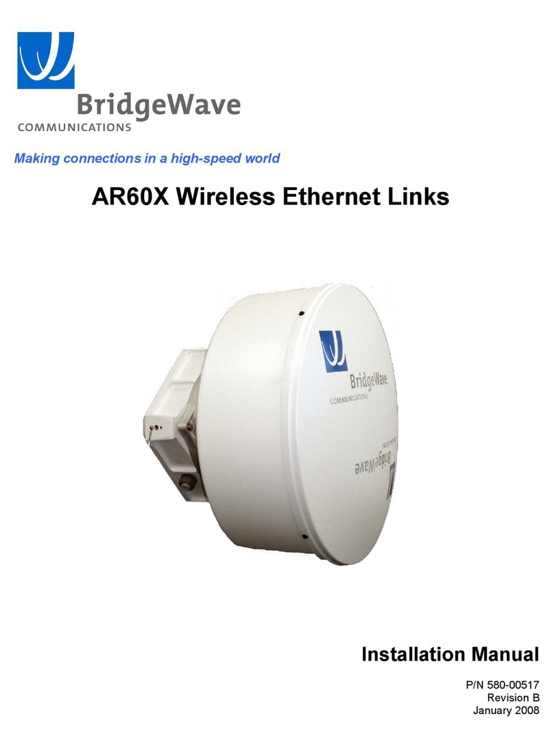
BridgeWave 80 Series Installation manual User manual

Makingconnectionsinahighspeedworld
80GHzWirelessEthernetLinks
InstallationManual
P/N58000519
RevisionD
January2008

AR/GE/FE/U80/80XInstallationManual
ii 58000519rev.D
CopyrightNotice&Disclaimer
Copyright©20042008BridgeWaveCommunications.Allrightsreserved.
PrintedintheUSA
Noportionofthispublicationmaybereproduced,copied,ordistributedwithoutthewrittenconsentof
BridgeWaveCommunications.BridgeWavereservestherighttoupdateorchangethematerialinthis
publicationatanytimewithoutnotice.BridgeWavehasmadeeveryefforttoensurethattheinformation
andtheinstructionscontainedinthepublicationareadequateandisnotresponsibleforanyerrorsor
omissionsduetotyping,printing,oreditingofthisdocument.
PurchasersofBridgeWaveproductsshouldmaketheirownevaluationtodeterminethesuitabilityof
eachsuchproductfortheirspecificapplication.BridgeWave’sobligationsregardingtheuseor
applicationofitsproductsshallbelimitedtothosecommitmentstothepurchasersetforthinits
StandardTermsandConditionsofSaleforadeliveredproduct.
Customersareresponsibleforobtainingproperoperatorlicenses.
Thispublicationhasbeenpreparedforprofessionalandproperlytrainedpersonnel,andthecustomer
assumesfullresponsibilitywhenusingtheinformationherein.
ExportControl
AllBridgeWaveradioproductsarerestrictedcommoditiesthatfallunderECCN5A002ofthe
DepartmentofCommerce.Theseproductsare"ENCrestricted"undersection740.17(b)(2)oftheExport
AdministrationRegulations(EAR).BridgeWaveproductsmayonlybeexported,reexported,
transferred,orretransferredinaccordancewithExportAdministrationRegulations.Diversioncontrary
toU.S.lawisexpresslyprohibited.
ProductCompatibility
Whileeveryefforthasbeenmadetoverifyoperationofthisproductwithmanydifferent
communicationsproductsandnetworks,BridgeWavemakesnoclaimofcompatibilitybetweenits
productsandothervendors’equipment.Customerisresponsibleforthoroughlyevaluatedthisproduct’s
performanceinthecommunicationsenvironmentinwhichitwillbeused.

AR/GE/FE/U80/80XInstallationManual
iii 58000519rev.D
Safety
CAUTION,WARNING,andDANGERstatementshavebeenplacedinthetexttoalertpersonnelof
possiblehazards.Thesestatementsmustbecloselyobserved.
Thefollowinggeneral safetyprecautionsmustbeobservedduringallphasesofoperationandserviceof
theproductscoveredinthismanual.Failuretocomplywiththeseprecautionsorwithspecificwarnings
elsewhereinthismanualwillfullyviolatesstandardsofdesign,manufacture,andintendeduseofthe
product.BridgeWaveassumesnoliabilityforthecustomer’sfailuretocomplywiththeserequirements.
· TheFE/GE/AR80(X)meetsallapplicableFCCsafetyrequirementsforradioequipment;
however,itisbesttoavoidprolonged,unnecessaryexposuretothefrontoftheradio
whileitisoperating
· Theoutdoorequipmentmustbeproperlygroundedtoprovidesomeprotectionagainst
voltagesurgesandbuiltupstaticcharges.Intheeventofashortcircuit,grounding
reducestheriskofelectricalshock.
ForinstallationsintheU.S.A.,refertoArticles810830oftheNationalElectricalCode,
ANSI/NFPANo.70,forinformationwithrespecttopropergroundingandapplicable
lightningprotectionforDCcables.
Forinstallationsinallothercountries,implementprotectioninaccordancewiththesafety
standardsandregulatoryrequirementsofthecountrywheretheequipmentistobe
installed.
· Donotinstalloroperatethisequipmentinthepresenceofflammablegasesorfumes.
Operationofanyelectricalinstrumentinsuchanenvironmentconstitutesadefinitesafety
hazard.
· Donotinstallsubstitutepartsorperformanyunauthorizedmodificationtotheequipment.
ChangesormodificationsnotexpresslyapprovedbyBridgeWavecanvoidtheuser’s
authoritytooperatetheequipment.

AR/GE/FE/U80/80XInstallationManual
iv 58000519rev.D
RegulatoryInformation
ThisdevicecomplieswithPart101oftheFCCRules.
LinksinstalledintheU.S.mustberegisteredwiththeFCCasprovidedforinPart101oftheFCC
regulations.FormoreinformationcontactBridgeWave’sCustomerServiceviaEmail
support@bridgewave.comorcallat4085676906.
EquipmentPrecautions
WaterandMoisture– The80GHzSystemisdesignedtowithstandprecipitationconditionstypically
encounteredwheninstalledoutdoors.
PowerSources Thisproductshouldonlybeoperatedwiththetypeofpowersupplyprovidedby
BridgeWaveCommunicationsInc.

AR/GE/FE/U80/80XInstallationManual
v 58000519rev.D
TableofContents
CopyrightNotice&Disclaimer ................ ii
ExportControl ......................................... ii
ProductCompatibility .............................. ii
Safety ...................................................... iii
RegulatoryInformation ............................iv
EquipmentPrecautions.............................iv
1 Introduction ........................................ 1
1.1 PurposeofManual........................ 1
1.2 PriorKnowledge........................... 1
1.3 ContactInformation...................... 2
2 SitePlanning ....................................... 3
2.1 General......................................... 3
2.2 EquipmentChecklist ..................... 3
2.3 LineofSight(LOS) ....................... 3
2.4 LinkDistance................................ 4
2.5 AntennaLocation.......................... 4
2.6 Cabling......................................... 5
2.7 Grounding&Lightning................. 6
2.8 Environmental .............................. 7
2.9 CablingDiagram .......................... 7
3 Installation .......................................... 8
3.1 General......................................... 8
3.2 EquipmentUnpacking................... 8
3.3 EquipmentInventory ..................... 9
3.4 InstallationTools ........................ 10
3.5 AntennaMountInstallation......... 10
3.6 AntennaandRadioInstallation ... 14
3.7 CableInstallation........................ 16
3.8 IceShieldCanopyInstallation .... 19
3.9 AntennaAlignment...................... 22
3.10 AutoCalibration ......................... 26
3.11 QUAL&RSLTestCable ............ 30
4 RadioLinkStatusIndicators ........... 32
5 ConnectingNetworkEquipment...... 33
5.1 NetworkPortStatistics................ 33
ApendixA Troubleshooting................. 34
ApendixB RSLVs.DistanceCharts... 36
Std.LimitedWarranty&SWLicense .... 37

AR/GE/FE/U80/80XInstallationManual
1 58000519rev.D
1 Introduction
1.1 PurposeofManual
Theinformationinthismanualisdirectedtopersonswhomustperformorcoordinatethetasks
associatedwiththeprocessofinstallingwirelesscommunicationdevices,andplanning
communicationnetworkapplications.
1.2 PriorKnowledge
Thismanualassumestheoperatorhasatleastbasicexperiencewithandanunderstandingof
wirelesstechnologyandsomefamiliaritywithconfiguringandoperatingnetworkingequipment.
Preferably,thepersoninstallingthisequipmentfully understandstheinformationcoveredinthis
manualpriortoattemptingtheseprocedures.
DANGER,WARNINGandNOTEstatementshavebeenplacedinvarioussectionsthroughoutthis
documenttoalertpersonnelofpossibletrafficaffectingissuesandtoprovideadditionaltipsand
helpfulinformation.Thesestatementsshouldbecloselyobserved.
Symbol Description
Indicatesthatpersonalinjurycanresultiftheuserdoesnot
complywiththegiveninstruction.
ADANGERstatementwilldescribethepotentialhazard,its
possibleconsequences,andthestepstoperformtoavoid
personalinjury.
Indicatesthatequipmentdamage,processfailureand/orlossof
datacanresultiftheuserdoesnotcomplywiththegiven
instructions.
AWARNINGstatementwilldescribethepotentialhazard,its
possibleconsequences,andthestepstoperformtoavoid
seriousequipmentdamage.
Providessupplementaryinformationtoemphasizeapointor
procedure,orprovidesatipforeasieroperation.

AR/GE/FE/U80/80XInstallationManual
2 58000519rev.D
1.3 ContactInformation
TechnicalAssistanceandCustomerService
BridgeWavedistributorsandresellersareauthorizedlocalserviceprovidersandareresponsiblefor
immediateTier1customersupport.Ifaproblemcannotberesolved,contactBridgeWaveCustomer
Serviceforassistance:
Location: SantaClara,CAUSA
Email: support@bridgewave.com
TechSupportHotLine: +1.408.567.6906
eServiceCenter http://bridgewave.com/support
ReturnMaterialAuthorization(RMA)
ShouldBridgeWaveequipmenthavetobereturnedforrepairorreplacement,anRMAnumbermust
beobtainedinadvancefromBridgeWaveoralocalBridgeWavedistributor.Whenreturning
equipment,besuretoclearlyindicatetheRMAnumberontheoutsideoftheshippingcarton.
BridgeWaveeServiceCenter:
Youcanviewknowledgebasecontent,openaticket,updateticketsandrequestRMAsonline24x7.
ToviewcurrentticketandRMAstatus,pleasegotohttp://bridgewave.com/supportandselect
‘eServiceCenter’tologinandenteryoursupportportal.
FirsttimeusersofeServiceCenterwillneedtosubmitarequesttoSupport@bridgewave.com,fora
loginIDandpassword.
AsupportengineerwillcontactyouwithyourloginIDandpassword.
BridgeWaveSales
Email: sales@bridgewave.com
InsideSales: +1.866.577.6908

AR/GE/FE/U80/80XInstallationManual
3 58000519rev.D
2 SitePlanning
2.1 General
Beforethestartofanyinstallation,asurveyoftheplanneddeploymentsiteshouldbeconducted
first.Thesurveyingpersonnelshouldbefullyfamiliarwiththedetailsandrequirementsneededto
successfullyinstallthe80GHzradiosystem.
2.2 EquipmentChecklist
Wesuggestthesitesurveyteammayneedthefollowingequipment:
· Binoculars(notalwaysrequired)
· WAAScapableGPSlocationdevice
· Tapemeasuretodeterminedistancesforcablerunstoingresspoints
· Digitalcamera(notalwaysrequired)
· Sitesurveyreportformtodocumentandhelpassesssite
· Signalingmirror(providedbutnotalwaysrequired)
· 7090GHzLinkRegistrationDatasheet.ContactBridgeWaveTechSupporttolearnwhere
onecanobtainthelatestversionofthisform.YoumayEmail support@bridgewave.comfor
thisrequestorrequestitonlineviaeServiceCenterhttp://bridgewave.com/support.
2.3 LineofSight(LOS)
The80GHzWirelessGigabitEthernetlinkrequiresLOSforproperoperation.Binocularsand
spottingmirrorsmaybeusedtoassistintheconfirmationofLOS.
PathplanningshouldincludeaninvestigationintofuturebuildingplansthatcouldblocktheLOS
path,andotherlongtermincrementalobstructionssuchastreegrowth.Intermittentobstructions
suchasaircraftatanearbyairportshouldalsobeconsidered.

AR/GE/FE/U80/80XInstallationManual
4 58000519rev.D
ThefollowingtabledetailstheminimumF1(FirstFresnel)clearanceneededfromobstaclesinorder
toensuretheradioswilloperateproperly.
Table2.31:MinimumPathClearance
PathLength
(meters)
MinimumF1Clearance
(meters)
PathLength
(miles)
MinimumF1Clearance
(feet)
1000 0.58 0.62 1.9
2000 0.82 1.24 2.7
5000 1.3 3.10 4.3
10000 1.8 6.21 5.9
2.4 LinkDistance
Measurementofthelinkdistanceisimportantin estimatingthelinkavailabilityandcalculating
expectedReceiveSignalLevel(RSL).ThismeasurementcanbeperformedusingtheLatitudeand
LongitudecoordinatereadingsfromaGlobalPositioningSystem(GPS)device,whichisplacednear
theproposedlocationsoftheantennas.AdditionallyGPSreadingwillberequiredinordertocomply
withtheFCCregistrationprocess.
TheMinimum80GHzLinkdistancesareasfollows:
· AR/GE/FE80:328feet(100meters)
· AR/GE/FE80X:1312feet(400meters)
Toestimatemaximumdistancesandavailabilitiesforagivenproductandregion,BridgeWave’s
PathAvailabilitycalculatorcanbeused.ToobtainthelatestversionofBridgeWave’sPath
Availabilitycalculator,contactBridgeWave’sCustomerServiceorsearcheServiceCenter
Knowledgebase.
2.5 AntennaLocation
Theoptimumlocationfortheantennasmustbedetermined.Theideallocationshouldprovidefor
easeoferectingandmountingtheantenna,aswellasprovidingunimpededLOStotheremote
location.Thefollowingfactorsshouldbetakenintoaccount:
· Typeofmounting—fixedorroofsafepolemounting.
· LocationoffiberandDCpowerwiringingress/egressofthebuilding.
· Lengthofcableruns.
· ConfirmedEarthGroundingconnectionpoints.
· Obstructions,includingallowancesfortreegrowth.
· Accessibilityoftheradiomountinglocation.
· Accessibilityofthesiteduringandafterworkinghours.

AR/GE/FE/U80/80XInstallationManual
5 58000519rev.D
2.6 Cabling
Theinstallationsiteshouldbeinspectedtodeterminetherunpathsforthefibercableandpower
cablefromtheradioequipmenttotheterminationpoint.Locationsforroofpenetrationshouldbe
identified.Theroutingandsecuringofallcablesshouldconformtoallapplicablecodesand
requirements.Dependingonthelikelihoodofdamageduetofoottrafficorequipmentmovement,
cablingconduitmayberequired.Themaximumcablerunlengthasspecifiedfortheequipment
beinginstalledmustnotbeexceeded,refertoTable2.61and2.62forcabletypesandlimitations.
TheradiorequiresLCtypeconnectorsonduplexmultimodefiberstoproperlyconnectbetweenthe
radioandtheusersnetworkequipment.Singlemodefiberconnectionsarenotsupportedforuse
withthestandardproduct.Thenetworkequipmentendofthefibersshouldbeterminatedwith
connectorsthatmatchtheuser’snetworkequipmentfiberinterface.
Table2.61:MaximumFiberLength
FiberCableLength CableType
Upto270meters 62.5/125μm
Upto500meters 50/125μm
The80GHzradioincludesa100240VACpoweradaptor,suitableforindooroperationonly,that
convertstheACvoltagefromastandardelectricaloutletinthewalltoDCvoltage.Foroutdoor
ratedpowersupplyoptions,contactBridgeWavecustomerservice.Theradiorequiresaminimumof
15.0VDCattheconnectorontheradiounit(24.0VDCmaximum)tofunctionproperly.
WhenplanningthecablerunfromtheindoorACpoweradaptortotheradiounit,itisrequiredtouse
thecablegauge(AWG)indicatedbelowtoensureadequatevoltageattheradio.Theindoorand
outdoorportionsoftheDCpowercablingmustconformtoallrespectiveindoorandoutdoor
nationalandlocalelectricalandbuildingcodes;notethatrequirementsmaydifferfortheindoorand
outdoorportionsofthecablingandthatagroundedsurgeprotectorisnormallyrequiredatthepoint
wherethecableentersthebuilding.TheDCpowercablingmustconsistoftwo12or14gauge
strandedconductorsbasedontherequiredcablerunlength.
Table2.62:MinimumDCCableSize
DCCableLength ConductorSize
Upto125meters 14AWG
(2.5mm²)
Upto200meters 12AWG
(4mm²)
Figure2.61showsastandard14gaugewirethathasbeenfittedwiththepowerconnectors
(provided)fortheradio’sinternalpowersupplynecessarytomatewiththe(notprovided)DCpower

AR/GE/FE/U80/80XInstallationManual
6 58000519rev.D
cables.Astandardcrimping/splicingtool(notprovided)isrequiredtoterminatethepower
connectorsontoa1412gaugecablerequiredforusewiththe80GHz.
On theradioendnoconnectorsarerequired;simplyscrewterminalstoappropriatepolarity.TheDC
powercableshouldbefedintotheconnectoronthecasingfirstandthenthegreenconnector
attachedtotheradioaftermakingastrainreliefcoilaroundtheelectronichousing.
Figure2.61: (Left)14gaugeDCpowercableterminated toradioend.(Right)DC14gaugecablefromthepower
supplyend.
2.7 Grounding&Lightning
Propergroundingoftheoutdoorequipmentreduces
electromagneticinterference,provideslightningprotection,and
protectsagainstelectricaldischarge.
Usingimpropertechniquesinlightningpronegeographicareas
mayposeadangertolocalpersonnel.
Thesourceandconnectionpointsforthebuildingtoearthground
inthevicinityoftheantennalocationshouldbedetermined.
Inadditiontogroundingtheequipment, BridgeWavestronglyrecommends,andlocalbuilding
codesmayrequire,theDCelectricalcabletobeprotectedfromelectricalsurgesbyasurge
suppressor.Thesurgesuppressormustbeinstalledat thepointwheretheDCelectricalcables
exit/enterthebuilding.

AR/GE/FE/U80/80XInstallationManual
7 58000519rev.D
Formoreinformationonrecommendedaccessorydevicesand
kits,contactBridgeWaveSales
2.8 Environmental
Thestructuretowhichtheequipmentwillbemountedshouldbeadequatetobearallwindand
weatherconditions.Theenvironmentalconditionsatthelocationmustconformtotheoperating
environmentspecifiedfortheequipment.
2.9 CablingDiagram
Figure2.91detailstheequipmentandcablingfoundonatypicalinstallationofBridgeWave’s
80GHzradioequipment.Useofthecopperportisoptionalandisnotrequiredformanagementagent
accessorfornormaldatatrafficoperation.
Figure2.91:SimpleNetworkDiagram

AR/GE/FE/U80/80XInstallationManual
8 58000519rev.D
3 Installation
3.1 General
Itisrecommendedthatinstallationpersonnelreadthissectioninitsentiretypriortoinstallingthe
BridgeWaveSystem.Duringaparticularphaseofinstallation,theusermayreferdirectlytothe
applicablesubsection.
TheInstallationsectioniscomprisedofsevensubsectionscoveringtheproceduresandguidelines
forinstallingtheBridgeWaveRadioSystem.
Subsections3.3 through 3.4 containinformationnecessarytopreparefortheequipmentinstallation.
Subsections3.5 through 3.8 coversequipmentinstallationprocedures.
Subsections3.9and3.10containinformationnecessaryforaligningtheantenna.
3.2 EquipmentUnpacking
Theradiosystemequipmentwillarriveintwoboxes—oneboxforthelowbandradioandonebox
forthehighbandradio.Locatethecorrectbox(lowbandorhighband)beforebeginning
installationbycheckingthelabelontheoutsideoftheboxorontheradioitself.Itisrecommended
thattheshippingcartonsandpackingmaterialsberetainedintheeventthatitisnecessarytoreturn
anyequipment.
Theradiatedpolaritycanbeidentifiedonunpackedradiosbythe
firstletterofthepolarityVorH(VerticalorHorizontal)onthe
topoftheunitchassisorbythepolarizationlabels.SeeFigure
3.61and3.62forfurtherdetails.

AR/GE/FE/U80/80XInstallationManual
9 58000519rev.D
3.3 EquipmentInventory
Followingareinventorylistsforatypicalsystem:
Table3.31:RadioandElectronicsPartsList
Qty Description
2ea. 80GHzradiounit(1lowbandtransmitunit&1highbandtransmitunit)
2ea. StandardPowerSupply(Indoorrated,100240VACinputto24VDCoutput)
1ea. CDwithManuals(1CDprovidedperpairofradios)
2ea. DCpowerconnectionset.(Includes2prongDCplugand2easlipfitplugs/receptacles)
2ea Antennaandmountkit
1ea. Signalingmirror
1ea. Hardresetbox
2ea. RSL/Qualitytestcable
2ea. StainlessSteelScrews#832X3/8,Phillipspanhead
Table3.32:AntennaandMountKitPartsList
Qty. Description
1ea. Antenna
1ea. Lowerpolemountassembly
1ea. Upperpolemountassembly
1ea. Antennamountingplate
2ea. 3/8bolts
2ea. 3/8lockwashers
2ea. 3/8flatwasher
2ea. 3/8nylonwasher
Formoreinformationonrecommendedaccessorydevicesand
spareparts,contactBridgeWaveSales

AR/GE/FE/U80/80XInstallationManual
10 58000519rev.D
Theradioissealedatthefactorywarrantystickersontheinner
(metal)coveroftheradio.Thereisnoneedtoopenthiscoverin
thefield.Tamperingwiththesesealswillvoidthewarranty.
3.4 InstallationTools
Thefollowingtools,notprovidedbyBridgeWave,arerequiredforinstallingtheradioandthe
antenna:
· Screwdriver,slotted0.1inchwide.
· Openendwrench9/16inch 2ea.
· Openendwrench1/2inch.
· Ratchetwith6inchextensionand9/16inchdeepsocket.
· Wirestripper/cutter/crimptool(1016gauge).
· Electricaltape.
· Fishtapeforpullingcable.
· Cabletiewraps.
· HandheldDVM(digitalvoltmeter)withstandardbananaplugreceptacles.
3.5 AntennaMountInstallation
1.Readtheseinstructionsbeforebeginninginstallation.Caution
shouldbeused.Qualifiedpersonsexperiencedwithantenna
assemblyandinstallationarerequiredforinstallation.
2. BridgeWaveCommunicationsInc.disclaimsanyresponsibility
orliabilityfordamageorinjuryresultingfromincorrectorunsafe
installationpractices.
3.Theantennahasbeenformedtoaveryclosetolerance
parabolicshape.Carefulhandlingandassemblyisrequiredto
avoiddentingthereflector,whichwoulddegradeantenna
performance.
Whenusingtheleftsideradiomountposition,theantennaendsup
gettingrotatedby180degrees.Thedrainholemustbeopenat
thebottomandclosedoffatthetopoftheantennatoprevent
wateringress.
· Forthe80X,movethebottomdrainholeplugtothetop
drainholeposition.
· FortheStandard80removethefourPhilipsheadscrews

AR/GE/FE/U80/80XInstallationManual
11 58000519rev.D
fromtheradomeandrotatetheradomesothedrainholeis
atthebottom.Becarefulnottocontaminate,damageor
smudgetheshinycoatingoftheantennasurfaceor
feedhornandmakesurethegasketisevenlyseatedwhen
reattachingtheradomecover.
1. Attachtheupperpolemounttotheantenna
mountingplate.
Confirmthatthemountiscenteredasshown.
Tightenboltssecurely.
Figure3.51: Upperpolemountattachedtoantenna
mountingplate
2. Attachthelowerpolemountandazimuthfine
adjustasshown.
Hardware:Flatwasher,bushing(insideeye),
flatwasher,lockwasher,bolt.
Figure3.52:Azimuthfineadjustassembly

AR/GE/FE/U80/80XInstallationManual
12 58000519rev.D
Confirmthatthemountiscenteredasshown.
Tightenboltssecurly.
Figure3.53: Lowerpolemountattachedtoantenna
mountingplate
3. Completedinstallationofpolemountwith
righthandoffsetfortheantenna.
Notethepositionoftheelevationfineadjust
hexnut.
Thepolemast(notsupplied)mustbe3.5to
4.5inch(89to114mm)O.D.SCH40steel
pipeorequivalent.
Figure3.54: Polemountwithrighthandoffset

AR/GE/FE/U80/80XInstallationManual
13 58000519rev.D
1. Optionallefthandantennaoffsetmount
preparation:
· Removeazimuthbolts
· Rotatetheantennamountingplate180º
· Replaceazimuthbolts
· Tightenazimuthbolts
Notethepositionoftheelevationfineadjust
hexnut.
Figure3.55: Polemountwithoptionallefthand
offset

AR/GE/FE/U80/80XInstallationManual
14 58000519rev.D
3.6 AntennaandRadioInstallation
It is critically important during installation to ensure the
radios on each side of the link are in the same polarization
(horizontalhorizontal or verticalvertical). A link that has a
radioononesideofthelinksetinthehorizontalpolarization
and the other side of the link set in the vertical polarization
willnotoperateproperly.
Itisalsocriticallyimportantthatahighbandradioispairedwith
alowbandradiotoensurethesystemwilloperateproperly.Prior
toinstallationcheckeachradiotoverifyoneisahighbandand
theotherisalowbandversion.Thelabelontheradiowill
indicatetheband(blueforhighorredforlow).
1. Installantennaandradio:
Thefirstletterofthedesignatedpolarizationis
stampedontoeachunittoidentifyorientations
whenthepolaritymarkispositionedontop:
“H”forhorizontal.
Figure3.61: 80GHzUnitmountedinhorizontal
polarity
2. Verifythatthefour(4)captive3/816boltswith
lockandflatwasherareinplace.
Itisimportantthatallfourboltsaretightened
evenly(handtight,1to2turnseachuntilthe
lockwasherisflattened).
Unitshavecaptiveboltsattachedtotheradio
housing.A9/16inchopenendwrenchis
requiredtotightenthem.
Unitshavecaptiveboltsattachedtothe2’
antenna.A1/2inchopenendwrenchis
requiredtotightenthem.
“V”forverticalpolarity.Figure3.62: 80GHzUnitmountedinvertical
polarity

AR/GE/FE/U80/80XInstallationManual
15 58000519rev.D
3. Coursealignazimuth(i.e.sidetosideor
horizontal)andtighten4carriageboltsto
securepolemounts.
4. Loosenthe4azimuthlockbolts.
5. Adjusteyeboltlengthusinga9/16”open
endwrenchtorequiredlocation.
6. Securethe4azimuthlockbolts(tighten
untllockwashersareflattend).
Figure3.63: Azimuthadjustmentbolts
(Note:Antennanotshownforclarity)
Itisveryimportantthattheazimuthboltsaretightenedbeforeanyelevation
adjustmentisattempted.Theverynarrowbeamwidthoftheseantennas(0.4º and0.9º)makesit
necessarytocompletelytightentheboltsoftheazimuthadjustmentwhileadjustingtheelevation
andviceversa.
7. Loosenthe2antennamountingbolts
8. Rotateelevationfineadjusthexnutas
requiredtosetcorrectelevation(i.e.updown
orvertical).
Donottrytoadjustthe
elevationfineadjustboltwithoutfirst
looseningtheantennabolts(step7).Doingso
maydamagethebrasselevationadjustment
pin.
9. Tightenthe2antennamountingboltsafter
correctelevationisset.
Figure3.64: Elevationfineadjustment
This manual suits for next models
9
Table of contents
Other BridgeWave Network Hardware manuals
Popular Network Hardware manuals by other brands

Cambium Networks
Cambium Networks TD-90 Series user guide

Johnson Controls
Johnson Controls Tyco exacqVision 2UA quick start guide

Trango Systems
Trango Systems TrangoLINK GigaPlus user manual

Fortinet
Fortinet FortiGate-50AM quick start guide

ADTRAN
ADTRAN AOC QSFP28 100G AOC QSFP28 100G 3M quick start

Aim
Aim ANET1553 Series user manual

Extron electronics
Extron electronics PVT CV D Specification sheet

PaloAlto Networks
PaloAlto Networks PA-400 Series quick start guide

SECO-LARM
SECO-LARM ENFORCER DRN-104-2TB installation manual

LaCie
LaCie Internet Space 2 datasheet

Frontier
Frontier APACHE user guide

Compro Technology
Compro Technology RS-2104 Quick installation guide