Elan WRITER User manual

Contents
Contents.......................................................................................................1
Chapter 1 Introduction........................................................................................2
1. Features...................................................................................................2
2. Package checklist.....................................................................................2
Chapter 2 Installation..........................................................................................3
1. ELAN Display writer .................................................................................3
2. Hardware requirements............................................................................6
3. Hardware Installation................................................................................7
4. Software Installation.................................................................................7
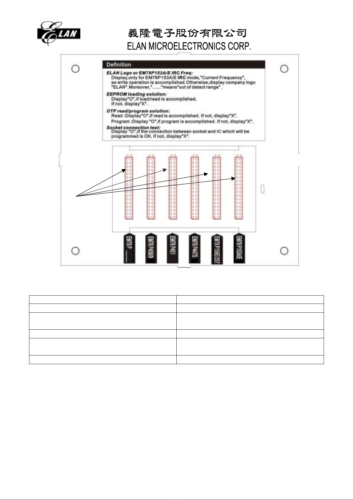
5. What is the self-diagnosis? ......................................................................7
Chapter 3 Introduction of the DWTR environment .............................................8
1.Getting start...............................................................................................8
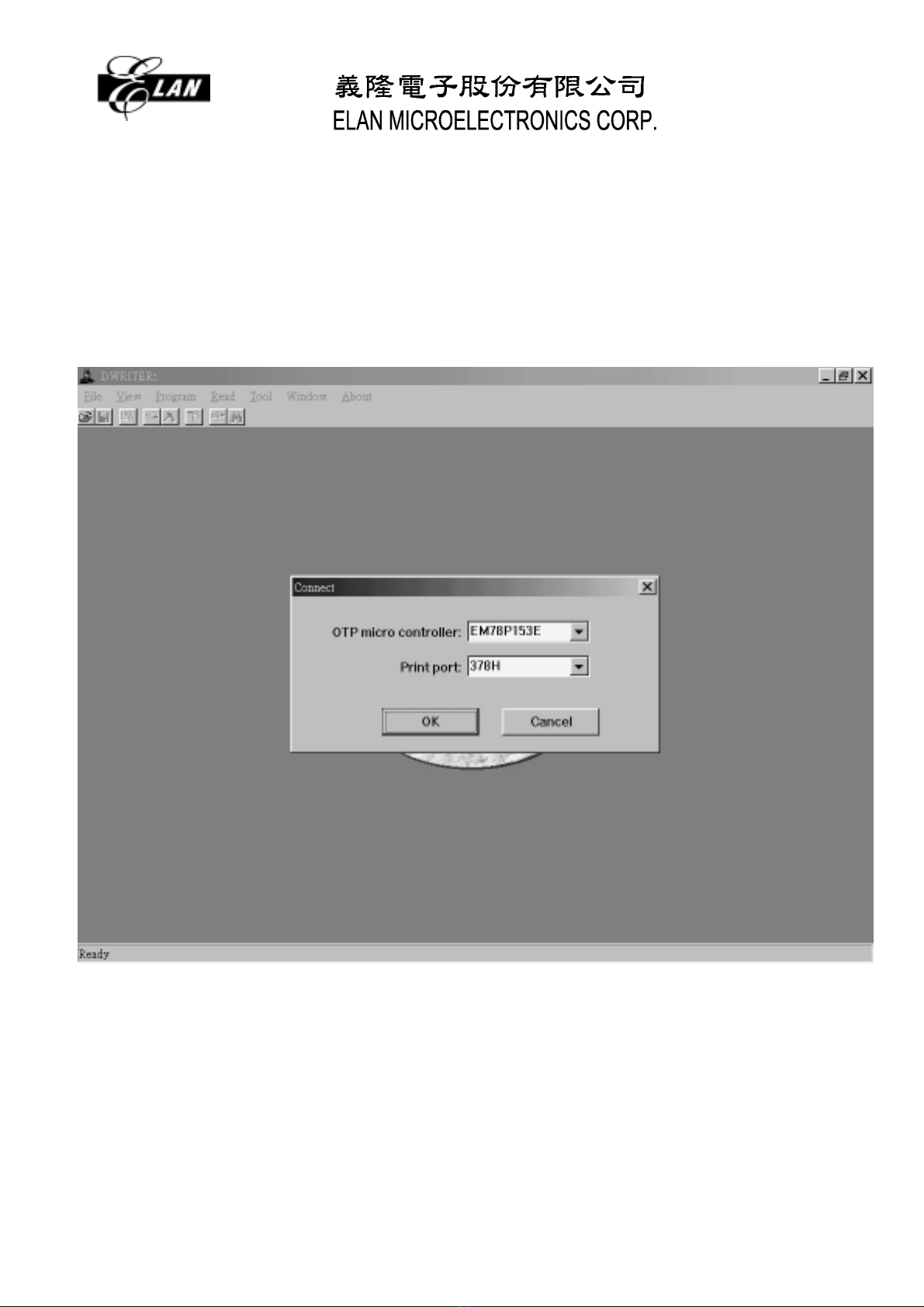
Procedure 1: Start DWTR ......................................................................8
Procedure 2: Open a CDS file................................................................9
Procedure 3: Program..........................................................................11
2.Introduction of environment.....................................................................12
(1) Menu...............................................................................................12
(2) Tool bar...........................................................................................12
(3) File menu........................................................................................13
(4) View menu......................................................................................16
(5) Program menu................................................................................17
(6) Read menu .....................................................................................19
(7) Tool menu.......................................................................................21
(8) Window...........................................................................................22
(9) About ..............................................................................................22
3.IRC Frequency Calibration......................................................................23
4.Error message.........................................................................................24
Chapter 4 Q & A ..........................................................................................28
1. How to check a failed buffer?.................................................................28
2. What is “Frequency Mode”?...................................................................28
3. What is “Code Protected”?.....................................................................28
4. What is status of LED?...........................................................................28
5. How to update your DWTR window software?.......................................28
1

Chapter 1Introduction
This user manual introduces the ELAN Display WRITER’s hardware, PC software for
window version , and how to use it. Display WRITER is a very user-friendly and highly portable
programmer used to program the all 8-bit family OTP (One Time Programmable) EM78P153S/
P156E/ P156N/ P257/ P447S/ P447N/ P451/ P451S/ P458/ P459/ P468N microcontrollers and
other EM78 family’s OTP microcontrollers in the future. It communicates with IBM PCs or
compatibles through a printer port. Moreover, the window version software ELAN supplies is
very easy to use and is available either in the compact disk or on the ELAN’s website. Due to
the result of its fast and accurate programming, the writer is quite suitable for pilot run, and
mass production as well.
1. Features
Easy-To-Use
LCM Display status
Internal RC frequency auto trim
One fits all programming (Multi-programming)
Either Corporate with PC or program by itself
File saved in binary format [filename.cds]
Offer versatile function: Read, Blank Check, Verify, Program, Save, Protect, and
Auto-Program
Self-diagnosis as power on
Search for printer port automatically
Portable, durable, and nice-looking
Clear indication between processes
2. Package checklist
ELAN DWTR 40-pin texttool (socket)
Compact Disk (Including MTP WRITER window version software, user’s manual,
Spec.)
18VDC switching power adaptor
WRITER User’s Guide
Printer cable
2

Chapter 2Installation
1. ELAN Display writer
L
ED
LCM
40-pin
texttool
Version
R
ed button
D
C power adaptor
P
rinter port connector
DC 18V
3

M
ode slots
CON6 CON5 CON4 CON3 CON2 CON1
Fig. 1: EM78 DWRITER
Table 1: Jumper corresponding table
Jumper connection position EM78PXXX
CON1 EM78P153S
CON2 EM78P156E/ EM78P156N
EM78P257
CON3 EM78P447S/ EM78P447N
CON4 EM78P451/ EM78P451S
EM78P468N
CON5 EM78P458/ EM78P459
4

Power indicator The LCM is on as power is supplied to the writer.
Program Indication General function: If using internal RC oscillator mode,
there will be the IRC frequency displayed on the LCM as
DWTR works alone.
Programming Counter function. This function will be active
if users keep pressing the red button for three seconds.
The LCM will switch to the programming counter function
page for five seconds as users release the red button and
will then return back to the general function page.
LCM information The LCM shows 2 kinds of funcion:
General function:
(A)
(M
)
(L)(K)(J)(I)(H)(F) (G)(E)
(D)(C)(B)
(A) EEPROM Check Sum.
(B) # of EEPROM Code Option word.
(C) EEPROM Code Option.
(D) ELAN logo or EM78P153S IRC Freq.
Display, only for EM78P153S IRC mode, ”Current
Frequency”, as write operation is accomplished.
Otherwise, display company logo “ELAN”.
Moreover
(E) OTP Check Sum.
(F) # of OTP Code Option word.
(G) OTP Code Option.
(H) OTP Read/Program solution.
Read: Display “O” , if reading is accomplished. If not,
display “X”
Program: Display “O”, if programming is
accomplished. If not, display “X”
Program: Display “O”, When burning in internal
RC mode, the internal frequency drift must be
guaranteed in ±5%. If the display of DWTR show
the “X” message, it’s means the internal
frequency is not of the guaranteed range.(Detail
description, please refer to chapter 3.)
(I) EEPROM Read/Loading solution.
Display “O”, if loading/reading is accomplished. If not,
display “X”
5

(J) Jump connection test.
Display “O”, if the connection between Jumpand IC
which will be programmed is OK. If not, display “X”.
(K) Socket connection test.
Display “O”, if the connection between socket and IC
which will be programmed is OK. If not, display
“X”.
(L) Current detector.
(M)Voltage detector.
Programming Counter function. This function will be active
if users keep pressing the red button for five seconds. The
LCM will switch to the programming counter function page
for ten seconds as users release the red button and will
then return back to the general function page.
(1)
(2)
(1) Total programming times after Power-On and
/RESET.
(2) Successful programming times after Power-On
and /RESET.
(3)
Busy indicator The green LED shows 4 kinds of information:
On: under programming. Wait for LED turns off.
Off: programming OK, reading OK, Load OK.
Slow blinking (1.5 cycles per second): programming
failed.
Type blinking (2.5 cycle per second): OTP not in socket.
Quick blinking (5 cycles per second): buffer reading failed.
◆Mode slots There are 6 mode slots which are EM78P153S/P156E/ P156N/ P257/
P447S /P447N/ P451/ P451S/P458/P459 from the left to the right. Each slot has 17
sets of jumper. Users can short jumpers with a set of jumper cap for a desired mode.
Program Bottom To press the red button to program independently.
Texttool / Socket To line up the bottom of a programmed IC with the bottom of
the socket.
DC power adapter To plug with a DC power supply is 18V.
Printer port Connector To communicate with IBM PCs or compatibles with the
printer cable.
2. Hardware requirements
IBM PC 486 or above,
6

640K RAM,
VGA monitor
Printer cable no longer than 2 meters
3. Hardware Installation
To short the desired mode slot shown in Fig. 1 with the jumper cap
To connect the PC and the unit with a printer cable, if collaboration of PC and the unit
is required
To insert the DC power adapter into the wall plug on the left hand side of the unit
Note:
To connect the printer cable before the power cable,
DWTR executes a self diagnosis for a few seconds as the power is supplied,
Never ever to put a programmed device on the texttool before the self
-diagnosis finishing.
4. Software Installation
Just execute the “setup.exe” file from the disk and then follow the step by step indications
to the end.
5. What is the self-diagnosis?
To check the buffer of DWTR. The LED is off if the check succeeds, otherwise it will
quickly blink.
To program virtually in order to sink the residual power produced by power-on. It is
the reason why users can not put a programmed device on the texttool before the
self-diagnosis finishes.
7

Chapter 3Introduction of the DWTR environment
1.Getting start
Procedure 1: Start DWTR
To double click the icon of ELAN WRITER on desktop, or to select desktop menu
[start]→[ELAN DWRITER] →[ELAN DWRITER].
Fig 2: DWTR initialized
8

Procedure 2: Open a CDS file
To choose [Open CDS file…] from [File] menu.
Step 1: Open file: The “Open” dialog box appears as being showed in Fig. 3. After
selecting a file, then press [OK] button. The source file window appears as being
shown in Fig. 4, and it consists of check sum, option, code option value and binary
data.
Step 2: Set Option: The Option dialog depicted in Fig. 5 and Fig. 6(only IRC user’s)
appears. In accordance with the application environment, designers can mix up a
suitable combination with the code option for the selected microcontroller. After
selecting options, then press [Update] button.
Step 3: Load: To keep loading source to Buffer until loading completely or press the [OK]
button depicted in Fig. 7, which is located on the up-left corner of the whole display. If
the [OK] button is pressed during dumping, the power of the hardware must be turned
off and turned on to resume the procedure of programming.
Fig.3: Open a CDS file
9

Fig. 4: Source file
Fig. 5: Code option
10

Fig. 6: IRC Code option
Fig. 7: Stop executing
Procedure 3: Program
To choose [Write] from [Program] menu.
To keep writing the OTP device or press the [OK] button depicted in Fig. 7
11

2.Introduction of environment
(1)Menu
Fig. 8:Menu
a. File: File manager includes “Open CDS file”, “Close file”, “Save”, “Save as CDS file”,
“Save as text file”, “Save read as CDS file”, “Save read as text file”, “Recent files”
and “Exit”.
b. View: To view opened window, which consists of “Source”,” Read ” and “Output.”
c. Program: Write function includes “Set option”, “Load ”,” Write”, “Auto”, “Protect”, and
“Write continuously.”
d. Read: Read consists of “Read OTP” and “Read Buffer”.
e. Tool: Tool contains “Connect”, “Blank check ”, “Verify”, “Compare”, “Find code”,
“Reset” and “Font.”
f. Window: Setting arrangement of windows. It includes “Title”, “Cascade” and “Arrange.”
h. About: To show about DWTR information.
(2)Tool bar
1 2 3 4 5 6 7 8
Fig. 9:Tool bar
In Fig. 9, the icons from left to right in the tool bar are (1) Open a CDS file, (2) Save (3)
Load, (4) Write, (5) Protect, (6) Read OTP, (7) Verify, and (8) find code.
12

(3) File menu
Fig. 10: Submenu of file
a.Open CDS file( open a file with CDS format)
Step 1: To select a file which extension file name is “cds”. The open dialog box is as
showing in Fig. 11.
Step 2: If all items are correct, press the [OK] button.
Step 3: The source file window shown as Fig. 12 consists of check sum, option, code
option value and code data.
Step 4: The set option dialog, depicted in Fig.5 and Fig.6, appears. In accordance with
the application environment, designers can mix up a suitable combination with
the code option for the selected microcontroller. After selecting options, then
press [Update] button.
Step 5: To keep loading source to buffer until loading completely or press the [OK]
button depicted in Fig.7, which is located on the up-left corner of the whole
display. If the [OK] button is pressed during dumping, the power of the
hardware must be turned off and turned on to resume the procedure of
programming.
13

Fig. 11: Open a CDS file
Fig. 12:Source window
b. Zip Function purpose: To storage the Latest version of Code Option Value
Step1: Open a CDS file, then press “Update” button to record the latest version Code
Option, is shown Fig13.
Step2: To select main Menu [File]->[Save ZIP file…], then the software will product a new
Zip file. The new Zip file is location in the project file path, if product success, is
shown Fig14.
14

Key-point: You must to re-save project CDS file one again, keep the CDS file is latest
version.
Stpe3: To select main Menu [File]->[Open Zip file…], then the software will loaded the
latest version Code Option, is shown in Fig15.
Fig13. Code option of CDS file
Fig14. Create the Zip file by DWriter Software
15

Fig15 Code Option is Open project.Zip
c.Close file: To close the active window.
d.Save: To save the contents of source window.
e.Save as CDS file: To save the contents of source window as an another CDS file.
f. Save as text file: To save the contents of source window as a text file.
g.Save Read as CDS file: To save the contents of read window as a CDS file.
h.Save Read as text file: To save the contents of read window as a text file.
i. Recent files: To record the recent closed files.
j. Exit.
(4) View menu
Fig. 16: View menu
a. Source: To activate the opened source window, which consists of checksum, option,
option value, program machine code.
b. Read: To activate the opened read window, which consists of checksum, option, option
value, program machine code.
c. Output: To activate the opened output window. The messages in the output window
16

are created by any actions.
(5) Program menu
Fig. 17: Program menu
a. Set option: In accordance with the application environment, designers can mix up
a suitable combination with the code option for the selected microcontroller. The
detail code option is described in microcontroller specifications. An example of the
EM78P153E code option is depicted in Fig. 5 and Fig.6.
b.Load: Two major tasks are performed. Firstly, to load an open source file to the buffer
inside DWTR. Secondly, to read and compare the buffer against the file. The code
dumping can be terminated by pressing the [OK] button depicted in Fig. 18, which is
located on the up-left corner of the whole display. However, the power of the hardware
must be turned off and turned on to resume the procedure of programming.
Fig. 18: Stop executing
c. Write:Two major tasks are performed. Firstly, to program the OTP device on the
socket. Secondly, to read and compare the OTP code against the file. The execution
result is displayed on the output window. Moreover, internal frequency displayed on the
LCM will just appear for about one second if using internal RC oscillator mode.
d. Auto: Three major tasks are performed. Firstly, to check whether the OTP is blank or
not. Secondly, to program the OTP device on the socket. Thirdly, to read and compare
the OTP code against the file. The execution result is displayed on the output window.
Moreover, internal frequency displayed on the LCM will just appear for about one
17

second if using internal RC oscillator mode.
e. Protect: Once the function of the protection is enabled, OTP memory will not be
readable any more.
f. Write continuously: To program one after another. The function of each item
depicted in Fig. 19 is described as follows:
“Count” indicates the number of devices programmed.
“Blank check” is to check whether the OTP device is blank or not.
“Verify” is to compare OTP code against source file.
“Rolling code” is to directly update the DWTR buffer with the sequence number. The
range of sequence value is from 0 to 64K, and the program code which is updated
must belong to “MOV A,K” or “RETL K”. So the low byte of sequence number is put
on the operand of “Lo address”, and the high byte of sequence number is put on
the operand of “Hi address” address.
“Low Byte” is address which the low byte of current value will replace the operand
value in the program code of the address.
“2’nd Byte” is address which the second byte of current value will replace the
operand value in the program code of the address.
“3’rd Byte” is address which the third byte of current value will replace the operand
value in the program code of the address.
“4’th Byte” is address which the forth byte of current value will replace the operand
value in the program code of the address.
“Current” is a current value of sequence number.
“Step” is a value, and the next current value is according to step value. The next
current is equal to addition of current value and step value.
“Success” is the number of devices programmed successfully.
“Error” is the number of devices programmed fail.
“Total” is the total number of good devices and failed devices.
“OK” is to execute.
“Exit” is to initialize all items and close the dialog.
“Cancel” is to close the dialog.
18

Fig. 19: Write continuously
(6) Read menu
Fig. 20:Read menu
a. Read OTP: Read data from OTP. The read OTP window appears as being shown in
Fig. 21. It consists of check sum, option, code option value and binary data, but OTP
not in socket or Short jump not connected shown in Fig. 22. Moreover, there will be no
frequency displayed on the LCM if using internal RC oscillator mode.
19

Fig. 21: Read OTP.
Fig.22. OTP not in socket or Short jump not connected
b. Read Buffer: Read data from buffer.
20
Table of contents
Other Elan Network Hardware manuals
Popular Network Hardware manuals by other brands

Patton electronics
Patton electronics 2888 Product brief

Enterasys
Enterasys 6E2xx Local Management User’s Guide

ADTRAN
ADTRAN 850-VoDSL Specifications

CTC Union
CTC Union FMUX101 user manual

IEI Technology
IEI Technology PUZZLE-9030 Series user manual

ADTRAN
ADTRAN Total Access 850 Installation and Maintenance