Brigade CVCFB User manual

Installation Guide
All Refrigerator/All Freezer

2
Table of Contents
Warnings & Important Information
_ _ _ _ _ _ _ _ _ _ _ _ _ _ _ _ _ _ _ _ _ _ _ _ _ _ _ _ _ _ _ _ _ _ _ _ _ _ _ _ _ _ _ _ _ _ _ _ _ _ _ _ _ _ _ _ _
3
Professional
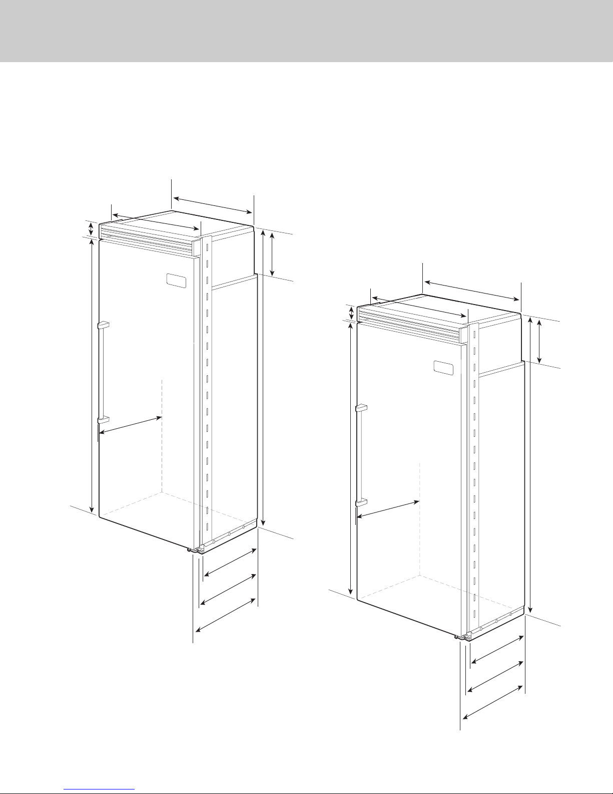
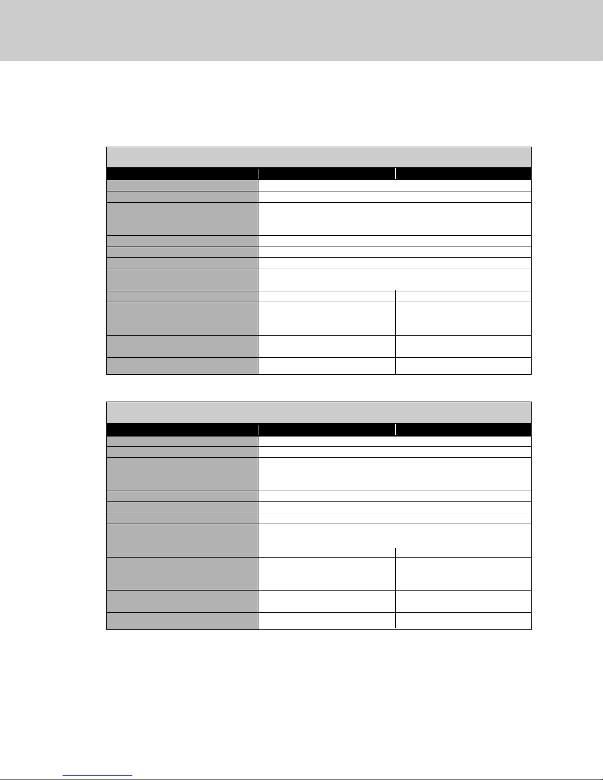
D i m e n s i o n s & S p e c i f i c a t i o n s ( 3 0 ” & 3 6 ” ) _ _ _ _ _ _ _ _ _ _ _ _ _ _ _ _ _ _ _ _ _ _ _ _ _ _ _ _ _ _ _ _ _ _ _ _ _ _ _ _ _ _ _ 6
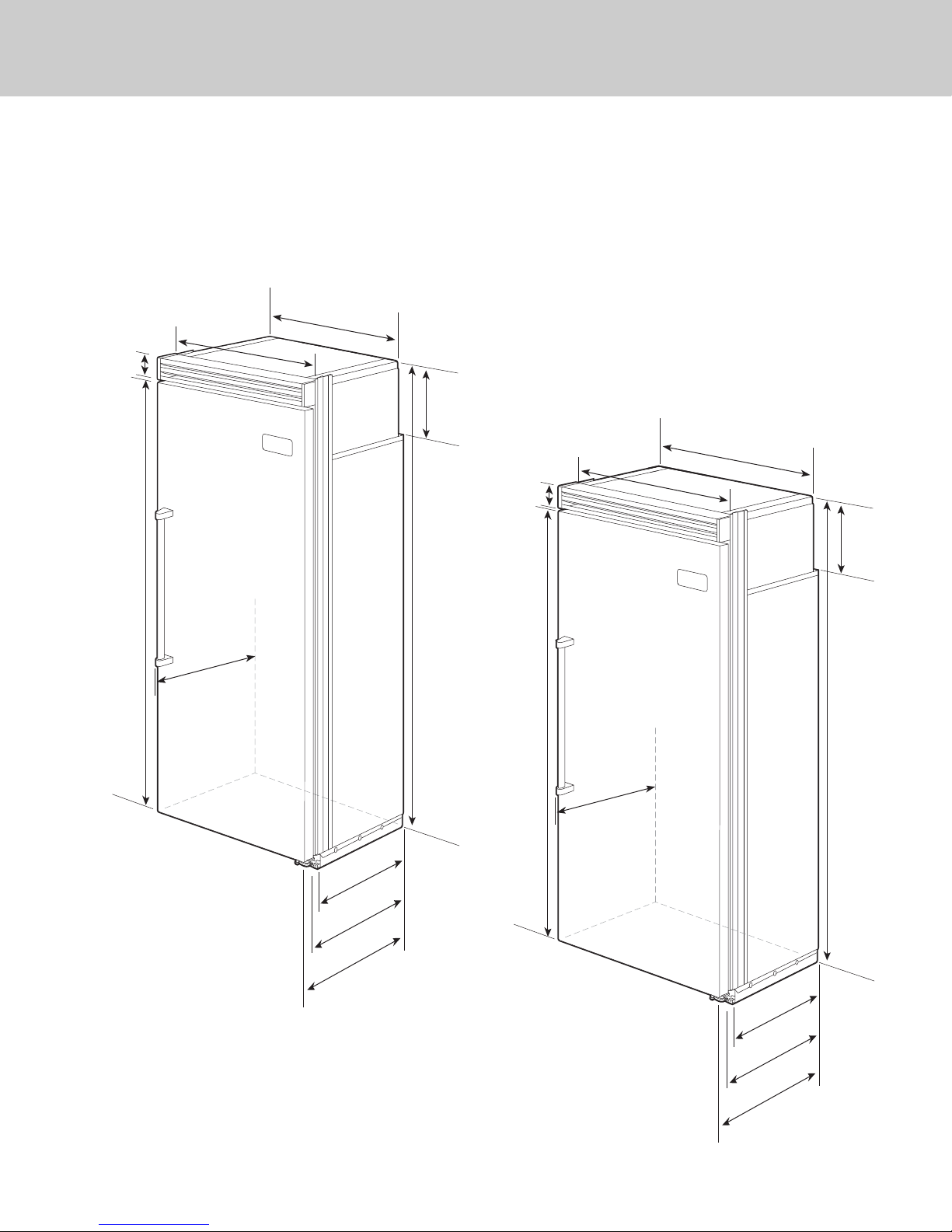
D i m e n s i o n s & S p e c i f i c a t i o n s ( 3 0 ” & 3 6 ” w i t h f l u s h m o u n t t r i m ) _ _ _ _ _ _ _ _ _ _ _ _ _ _ _ _ _ _ _ _ _ _ _ 8
C u t o u t D i m e n s i o n s ( 3 0 ” ) _ _ _ _ _ _ _ _ _ _ _ _ _ _ _ _ _ _ _ _ _ _ _ _ _ _ _ _ _ _ _ _ _ _ _ _ _ _ _ _ _ _ _ _ _ _ _ _ _ _ _ _ _ _ _ _ 1 0
A n t i - T i p D i m e n s i o n s ( 3 0 ” ) _ _ _ _ _ _ _ _ _ _ _ _ _ _ _ _ _ _ _ _ _ _ _ _ _ _ _ _ _ _ _ _ _ _ _ _ _ _ _ _ _ _ _ _ _ _ _ _ _ _ _ _ _ _ _ 1 1
C u t o u t D i m e n s i o n s ( 3 6 ” ) _ _ _ _ _ _ _ _ _ _ _ _ _ _ _ _ _ _ _ _ _ _ _ _ _ _ _ _ _ _ _ _ _ _ _ _ _ _ _ _ _ _ _ _ _ _ _ _ _ _ _ _ _ _ _ _ 1 2
A n t i - T i p D i m e n s i o n s ( 3 6 ” ) _ _ _ _ _ _ _ _ _ _ _ _ _ _ _ _ _ _ _ _ _ _ _ _ _ _ _ _ _ _ _ _ _ _ _ _ _ _ _ _ _ _ _ _ _ _ _ _ _ _ _ _ _ _ _ 1 3
D i m e n s i o n s & S p e c i f i c a t i o n s ( D u a l 3 0 ” / D u a l 3 0 ” & 3 6 ” ) _ _ _ _ _ _ _ _ _ _ _ _ _ _ _ _ _ _ _ _ _ _ _ _ _ _ _ _ 1 4
Dimensions & Specifications (Dual 30”/ Dual 30” & 36” with flush mount trim) _________ 18
C u t o u t D i m e n s i o n s ( D u a l 3 0 ” ) _ _ _ _ _ _ _ _ _ _ _ _ _ _ _ _ _ _ _ _ _ _ _ _ _ _ _ _ _ _ _ _ _ _ _ _ _ _ _ _ _ _ _ _ _ _ _ _ _ _ _ _ 2 2
A n t i - T i p D i m e n s i o n s ( D u a l 3 0 ” ) _ _ _ _ _ _ _ _ _ _ _ _ _ _ _ _ _ _ _ _ _ _ _ _ _ _ _ _ _ _ _ _ _ _ _ _ _ _ _ _ _ _ _ _ _ _ _ _ _ _ _ 2 3
C u t o u t D i m e n s i o n s ( D u a l 3 0 ” & 3 6 ” ) _ _ _ _ _ _ _ _ _ _ _ _ _ _ _ _ _ _ _ _ _ _ _ _ _ _ _ _ _ _ _ _ _ _ _ _ _ _ _ _ _ _ _ _ _ _ 2 4
A n t i - T i p D i m e n s i o n s ( D u a l 3 0 ” & 3 6 ” ) _ _ _ _ _ _ _ _ _ _ _ _ _ _ _ _ _ _ _ _ _ _ _ _ _ _ _ _ _ _ _ _ _ _ _ _ _ _ _ _ _ _ _ _ _ 2 5
C u t o u t D i m e n s i o n s ( D u a l 3 6 ” ) _ _ _ _ _ _ _ _ _ _ _ _ _ _ _ _ _ _ _ _ _ _ _ _ _ _ _ _ _ _ _ _ _ _ _ _ _ _ _ _ _ _ _ _ _ _ _ _ _ _ _ _ 2 6
A n t i - T i p D i m e n s i o n s ( D u a l 3 6 ” ) _ _ _ _ _ _ _ _ _ _ _ _ _ _ _ _ _ _ _ _ _ _ _ _ _ _ _ _ _ _ _ _ _ _ _ _ _ _ _ _ _ _ _ _ _ _ _ _ _ _ _ 2 7
Cabinet Information _______________________________________________________ _ _ _ _ _ 2 8
Cabinet Information (with flush mount trim) ________________________________________ 30
Custom Side Panel Dimensions __________________________________________________ _ _ _ _ 3 2
Custom Side Panel Dimensions (with flush mount trim)__________________________________ 33
General Information _______________________________________________________ _ _ _ _ _ _ _ _ _ 3 4
U n p a c k i n g & M o v i n g _ _ _ _ _ _ _ _ _ _ _ _ _ _ _ _ _ _ _ _ _ _ _ _ _ _ _ _ _ _ _ _ _ _ _ _ _ _ _ _ _ _ _ _ _ _ _ _ _ _ _ _ _ _ _ _ _ _ _ _ 3 6
F l u s h M o u n t S i d e Tr i m I n s t a l l a t i o n _ _ _ _ _ _ _ _ _ _ _ _ _ _ _ _ _ _ _ _ _ _ _ _ _ _ _ _ _ _ _ _ _ _ _ _ _ _ _ _ _ _ _ _ _ _ _ _ _ _ _ _ 3 7
I n s t a l l a t i o n _ _ _ _ _ _ _ _ _ _ _ _ _ _ _ _ _ _ _ _ _ _ _ _ _ _ _ _ _ _ _ _ _ _ _ _ _ _ _ _ _ _ _ _ _ _ _ _ _ _ _ _ _ _ _ _ _ _ _ _ _ _ _ _ _ _ _ _ _ _ _ _ _ 3 7
H i n g e A d j u s t m e n t _ _ _ _ _ _ _ _ _ _ _ _ _ _ _ _ _ _ _ _ _ _ _ _ _ _ _ _ _ _ _ _ _ _ _ _ _ _ _ _ _ _ _ _ _ _ _ _ _ _ _ _ _ _ _ _ _ _ _ _ _ _ 3 8
K i c k p l a t e I n s t a l l a t i o n _ _ _ _ _ _ _ _ _ _ _ _ _ _ _ _ _ _ _ _ _ _ _ _ _ _ _ _ _ _ _ _ _ _ _ _ _ _ _ _ _ _ _ _ _ _ _ _ _ _ _ _ _ _ _ _ _ _ _ _ 4 0
Door Stop Adjustment _______________________________________________________ _ _ _ 4 1
F i n a l I n s t a l l a t i o n _ _ _ _ _ _ _ _ _ _ _ _ _ _ _ _ _ _ _ _ _ _ _ _ _ _ _ _ _ _ _ _ _ _ _ _ _ _ _ _ _ _ _ _ _ _ _ _ _ _ _ _ _ _ _ _ _ _ _ _ _ _ _ _ 4 1
Performance Checklist ______________________________________________________ _ _ _ _ _ _ _ _ 4 3
C o n t r o l P a n e l s _ _ _ _ _ _ _ _ _ _ _ _ _ _ _ _ _ _ _ _ _ _ _ _ _ _ _ _ _ _ _ _ _ _ _ _ _ _ _ _ _ _ _ _ _ _ _ _ _ _ _ _ _ _ _ _ __ _ _ _ _ _ _ _ _ _ _ _ 4 4
Service & Registration______________________________________________________ _ _ _ _ _ _ _ _ _ 4 5

3
IMPORTANT–Please Read and Follow!
• Make sure that incoming voltage is the same
as unit rating. An electric rating plate
specifying voltage, frequency, wattage,
amperage, and phase is attached to the
product.
• To reduce the risk of fire, electric shock, or
injury to persons, installation work and
electrical wiring must be done by qualified
people in accordance with all applicable
codes and standards, including fire-rated
construction.
• The installer should leave these instructions
with the consumer who should retain them
for local inspector’s use and for future
reference.
Your safety and the safety of others is very
important.
We have provided many important safety
messages in this manual and on your
appliance. Always read and obey all
safety messages.
This is the safety alert symbol. This
symbol alerts you to hazards that
can kill or hurt you and others.
All safety messages will be preceded by the
safety alert symbol and the word“DANGER”
or “WARNING.”These words mean:
DANGER
You will be killed or seriously injured if
you don’t follow instructions.
WARNING
You can be killed or seriously injured if
you don’t follow instructions.
All safety messages will identify the
hazard, tell you how to reduce the chance
of injury, and tell you what can happen if
the instructions are not followed.

IMPORTANT–Please Read and Follow!
4
A GFI
shall be used if required by NFPA-70 (National Electric Code), federal/state/local laws, or
local ordinances.
• The required use of a GFI is normally related to the location of a receptacle with respect to
any significant sources of water or moisture.
• Viking Range, LLC will NOT warranty any problems resulting from GFI outlets which are not
installed properly or do not meet the requirements below.
If the use of a GFI is required
, it should be:
• Of the receptacle type (breaker type or portable type NOT recommended)
• Used with permanent wiring only (temporary or portable wiring NOT recommended)
• On a dedicated circuit (no other receptacles, switches or loads in the circuit)
• Connected to a standard breaker of appropriate size (GFI breaker of the same size NOT
recommended)
• Rated for Class A (5 mA +/- 1 mA trip current) as per UL 943 standard)
• In good condition and free from any loose-fitting gaskets (if applicable in outdoor situations)
• Protected from moisture (water, steam, high humidity) as much as reasonably possible

IMPORTANT–Please Read and Follow!
5
WARNING
ELECTRICAL SHOCK
HAZARD
Disconnect power or turn
power disconnect switch to
OFF position before removing
top grille. Failure to do so can
result in death or electrical shock.
WARNING
TIP OVER HAZARD
Appliance is top
heavy and tips easily
when not completely
installed. Keep doors
closed until appliance
is completely installed
and secured per installation instructions.
Use two or more people to move and
install appliance. Failure to do so can
result in death or serious injury.
Most of the unit’s weight is at the top. Extra care is needed when moving the unit to prevent
tipping. Use cardboard shipping material or plywood under unit until it is installed in the
operating position to protect floor surface.
It is your responsibility to:
• comply with installation specifications and dimensions.
• properly install unit.
• remove any moldings or decorative panels that prevent the unit from being serviced.
• make sure that you have these materials (not provided with your unit), which are necessary
for proper installation:
• 1/4” (6 mm) copper tubing with shutoff valve
• 6– #8 x 3” (7.6 cm) wood screws (longer screws may be required)
• 1– Saddle valve (do not use self-piercing feature of the valve)
• assure that floor will support unit, door panels and contents (approximately 1200 pounds [540 kg]).
• provide a properly grounded electrical outlet.
• assure that location will permit appliance doors to open 90° minimum.

24”
(61.0 cm)
35”
(88.9 cm)
75–15/16”
(192.9 cm)
3–19/32”
(9.1 cm)
)
36”
36”
(91.5 cm)
(91.5 cm)
36”
(91.5 cm)
26-1/2”
(67.3 cm)
9–5/32”
(23.3 cm)
82–3/4”
(210.2 cm)
min.
to
84–1/16”
(213.5 cm)
max.
20–3/4”
(52.7 cm)
22–3/16”
(56.4 cm)
24”
(61.0 cm)
29”
(73.7 cm)
75–15/16”
(192.9 cm
)
3–19/32”
(9.1 cm)
30”
30”
(76.2 cm)
(76.2 cm)
30”
(76.2 cm)
9–5/32”
(23.3 cm)
82–3/4”
(210.2 cm)
min.
to
84–1/16”
(213.5 cm)
max.
20–3/4”
(52.7 cm)
22–3/16”
(56.4 cm)
26-1/2”
(67.3 cm)
Dimensions
6
30” All Refrigerator/All Freezer
36” All Refrigerator/All Freezer

7
Specifications
30” All Refrigerator/All Freezer
Description CVCFB CVCRB
Overall width 30” (76.2 cm)
Overall height from bottom 82-3/4” (210.2 cm) min. to 84-1/16” (213.5 cm) max.
Overall depth from rear To front edge of side trim: 22-3/16” (56.4 cm)
To front of top grille: 24” (61.0 cm)
To front of handle endcap: 26-1/2” (67.3 cm)
Cutout width 29-5/8” (75.2 cm) min. to 29-3/4” (75.6 cm) max.
Cutout height 82-7/8” (210.5 cm) min. to 84-1/16” (213.5 cm) max.
Cutout depth 24” (61.0 cm) min.
Electrical requirements 115 volt, 60 Hz, 15 amp dedicated circuit; 3-wire cord with
grounded 3-prong plug attached to product
Maximum amp usage 9.1 amps 5.7 amps
Inlet water requirements 1/4” copper tubing inlet
waterline; minimum 20 psi; N/A
maximum 120 psi
Overall interior dimensions
Total capacity 15.9 cu. ft. (450 liters) 18.4 cu. ft. (522 liters)
Approximate shipping weight 550 lbs. (247.5 kg) 525 lbs. (236.3 kg)
36” All Refrigerator/All Freezer
Description CVCFB CVCRB
Overall width 36” (91.5 cm)
Overall height from bottom 82-3/4” (210.2 cm) min. to 84-1/16” (213.5 cm) max.
Overall depth from rear To front edge of side trim: 22-3/16” (56.4 cm)
To front of top grille: 24” (61.0 cm)
To front of handle endcap: 26-1/2” (67.3 cm)
Cutout width 35-5/8” (90.5 cm) min. to 35-3/4” (90.8 cm) max.
Cutout height 82-7/8” (210.5 cm) min. to 84-1/16” (213.5 cm) max.
Cutout depth 24” (61.0 cm) min.
Electrical requirements 115 volt, 60 Hz, 15 amp dedicated circuit; 3-wire cord with
grounded 3-prong plug attached to product
Maximum amp usage 9.5 amps 6.5 amps
Inlet water requirements 1/4” copper tubing inlet
waterline; minimum 20 psi; N/A
maximum 120 psi
Overall interior dimensions
Total capacity 19.2 cu. ft. (544 liters) 22.8 cu. ft. (646 liters)
Approximate shipping weight 605 lbs. (272.3 kg) 590 lbs. (265.5 kg)

24”
(61.0 cm)
35”
(88.9 cm)
75–15/16”
(192.9 cm)
3–19/32”
(9.1 cm)
36”
36”
(91.5 cm)
(91.5 cm)
36”
(91.5 cm)
26–1/2”
(67.3 cm)
9–5/32”
(23.3 cm)
82–3/4”
(210.2 cm)
min.
to
84–1/16”
(213.5 cm)
max.
20–3/4”
(52.7 cm)
23–3/8”
(59.4 cm)
24”
(61.0 cm)
29”
(73.7 cm)
75–15/16”
(192.9 cm
)
3–19/32”
(9.1 cm)
30”
30”
(76.2 cm)
(76.2 cm)
30”
(76.2 cm)
9–5/32”
(23.3 cm)
82–3/4”
(210.2 cm)
min.
to
84–1/16”
(213.5 cm)
max.
20–3/4”
(52.7 cm)
23–3/8”
(59.4 cm)
26–1/2”
(67.3 cm)
Dimensions
8
30” All Refrigerator/All Freezer
with Flush Mount Trim
36” All Refrigerator/All Freezer
with Flush Mount Trim
Note: Flush Mount Trim (PBIRFTKSS) purchased separately.

Specifications
9
30” All Refrigerator/All Freezer with Flush Mount Trim
Description CVCFB/Flush Mount CVCRB/Flush Mount
Overall width 30” (76.2 cm)
Overall height from bottom 82-3/4” (210.2 cm) min. to 84-1/16” (213.5 cm) max.
Overall depth from rear To front edge of side trim: 23-3/8” (59.4 cm)
To front of top grille: 24” (61.0 cm)
To front of handle endcap: 26-1/2” (67.3 cm)
Cutout width 30” (74.9 cm)
Cutout height 82-7/8” (210.5 cm) min. to 84-1/16” (213.5 cm) max.
Cutout depth 24” (61.0 cm) min.
Electrical requirements 115 volt, 60 Hz, 15 amp dedicated circuit; 3-wire cord with
grounded 3-prong plug attached to product
Maximum amp usage 9.1 amps 5.7 amps
Inlet water requirements 1/4” copper tubing inlet
waterline; minimum 20 psi; N/A
maximum 120 psi
Overall interior dimensions
Total capacity 15.9 cu. ft. (450 liters) 18.4 cu. ft. (522 liters)
Approximate shipping weight 550 lbs. (247.5 kg) 525 lbs. (236.3 kg)
36” All Refrigerator/All Freezer with Flush Mount Trim
Description CVCFB/Flush Mount CVCRB/Flush Mount
Overall width 36” (91.5 cm)
Overall height from bottom 82-3/4” (210.2 cm) min. to 84-1/16” (213.5 cm) max.
Overall depth from rear To front edge of side trim: 23-3/8” (59.4 cm)
To front of top grille: 24” (61.0 cm)
To front of handle endcap: 26-1/2” (67.3 cm)
Cutout width 36” (91.4 cm)
Cutout height 82-7/8” (210.5 cm) min. to 84-1/16” (213.5 cm) max.
Cutout depth 24” (61.0 cm) min.
Electrical requirements 115 volt, 60 Hz, 15 amp dedicated circuit; 3-wire cord with
grounded 3-prong plug attached to product
Maximum amp usage 9.5 amps 6.5 amps
Inlet water requirements 1/4” copper tubing inlet
waterline; minimum 20 psi; N/A
maximum 120 psi
Overall interior dimensions
Total capacity 19.2 cu. ft. (544 liters) 22.8 cu. ft. (646 liters)
Approximate shipping weight 605 lbs. (272.3 kg) 590 lbs. (265.5 kg)

9”
(22.9 cm)
73–3/8”
(186.4 cm)
82–7/8”
(210.5 cm) min.
anti-tip board &
opening height
84–1/16”
(213.5 cm) max.
anti-tip board &
opening height
29–5/8”
(75.2 cm) min.
to
29-3/4”
(75.6 cm) max.
30”
(76.2 cm)
Flush Mount only
24”
(61.0 cm)
Electric Outlet Location
Water Line Entry Area
Note: Shown for All Freezer Only
29–5/8”
(75.2 cm)
6–3/4”
(17.1 cm)
7–5/8”
(19.4 cm)
3”
(7.6 cm)
5/8”
(1.5 cm)
5/8”
(1.5 cm)
10–1/2”
(26.7 cm)
5/8”
(1.5 cm)
10–3/4”
(27.3 cm)
1”
(2.5 cm)
3–5/8”
(9.2 cm)
Optional floor
water line entry
30”
(76.2 cm)
Flush Mount only
See Anti-Tip board installation
6”
(15.2 cm)
9”
(22.9 cm)
Cutout Dimensions
10
30” All Refrigerator/All Freezer

Bottom of anti-tip board is 3–7/8” (9.8 cm) below opening height.
Note: Top of unit must be placed firmly under anti-tip board.
Anti-Tip Location
Flush Mount Anti-Tip Location
NOTE: If unit is installed deeper than
24” (61.0 cm),then shim behind the mounting
board by the difference.
NOTE: If unit is installed deeper than
24” (61.0 cm), then shim behind the mounting
board by the difference.
Two 2”x 4” mounting boards
3” (7.6 cm) x 3-1/2” (8.9 cm)
One 2”x 4” mounting board
1–1/2” (3.8 cm) x 3-1/2” (8.9 cm)
79–3/8”
(201.6 cm) min.
to bottom of
anti-tip board
80–1/2”
(204.6 cm) max.
to bottom of
anti-tip board
23”
(58.4 cm)
3–1/2”
(8.9 cm)
3”
(7.6 cm)
23”
(58.4 cm)
3–1/2”
(8.9 cm)
1–1/2”
(3.8 cm)
Anti-Tip Dimensions
11
30” All Refrigerator/All Freezer

9”
(22.9 cm)
73–3/8”
(186.4 cm)
82–7/8”
(210.5 cm) min.
anti-tip board &
opening height
84–1/16”
(213.5 cm) max.
anti-tip board &
opening height
35–5/8”
(90.5 cm) min.
to
35-3/4”
(90.8 cm) max.
36”
(91.4 cm)
Flush Mount only
24”
(61.0 cm)
Electric Outlet Location
Water Line Entry Area
Note: Shown for All Freezer Only
35–5/8”
(90.5 cm)
6–3/4”
(17.1 cm)
7–5/8”
(19.4 cm)
3”
(7.6 cm)
5/8”
(1.5 cm)
5/8”
(1.5 cm)
10–1/2”
(26.7 cm)
5/8”
(1.5 cm)
10–3/4”
(27.3 cm)
1”
(2.5 cm)
3–5/8”
(9.2 cm)
Optional floor
water line entry
36”
(91.4 cm)
Flush Mount only
See Anti-Tip board installation
6”
(15.2 cm)
9”
(22.9 cm)
Cutout Dimensions
12
36” All Refrigerator/All Freezer

Bottom of anti-tip board is 3–7/8” (9.8 cm) below opening height.
Note: Top of unit must be placed firmly under anti-tip board.
79–3/8”
(201.6 cm) min.
to bottom of
anti-tip board
80–1/2”
(204.6 cm) max.
to bottom of
anti-tip board
Anti-Tip Location
Flush Mount Anti-Tip Location
NOTE: If unit is installed deeper than
24” (61.0 cm), then shim behind the mounting
board by the difference.
NOTE: If unit is installed deeper than
24” (61.0 cm), then shim behind the mounting
board by the difference.
Two 2”x 4” mounting boards
3” (7.6 cm) x 3-1/2” (8.9 cm)
One 2”x 4” mounting board
1–1/2” (3.8 cm) x 3–1/2” (8.9 cm)
29–1/2”
(74.9 cm)
3–1/2”
(8.9 cm)
3”
(7.6 cm)
29–1/2”
(74.9 cm)
3–1/2”
(8.9 cm)
1–1/2”
(3.8 cm)
Anti-Tip Dimensions
13
36” All Refrigerator/All Freezer

24”
(61.0 cm)
1”
(2.54 cm)
Between Units
9–5/32”
(23.3 cm)
82–3/4”
(210.2 cm)
min.
to
84–1/16”
(213.5 cm)
max.
20–3/4”
(52.7 cm)
22–3/16”
(56.4 cm)
75–15/16”
(192 .9 cm
)
3–19/32”
(9.1 cm)
29”
(73.7 cm)
29”
(73.7 cm)
30”
30”
(76.2 cm)
(76.2 cm)
30”
(76.2 cm)
30”
30”
(76.2 cm)
(76.2 cm)
30”
(76.2 cm)
26-1/2”
(67.3 cm)
Dimensions
14
Dual 30” All Refrigerator/All Freezer

24”
(61.0 cm)
1”
(2.54 cm)
Between Units
35”
(88.9 cm)
36”
36”
(91.5 cm)
(91.5 cm)
36”
(91.5 cm)
9–5/32”
(23.3 cm)
82–3/4”
(210.2 cm)
min.
to
84–1/16”
(213.5 cm)
max.
20–3/4”
(52.7 cm)
22–3/16”
(56.4 cm)
29”
(73.7 cm)
75–15/16”
(192 .9 cm
)
3–19/32”
(9.1 cm)
30”
30”
(76.2 cm)
(76.2 cm)
30”
(76.2 cm)
26-1/2”
(67.3 cm)
Dimensions
15
Dual 30” & 36” All Refrigerator/All Freezer

24”
(61.0 cm)
1”
(2.54 cm)
Between units
35”
(88.9 cm)
35”
(88.9 cm)
36”
36”
(91.5 cm)
(91.5 cm)
36”
(91.5 cm)
36”
36”
(91.5 cm)
(91.5 cm)
36”
(91.5 cm)
9–5/32”
(23.3 cm)
82–3/4”
(210.2 cm)
min.
to
84–1/16”
(213.5 cm)
max.
20–3/4”
(52.7 cm)
22–3/16”
(56.4 cm)
75–15/16”
(192 .9 cm
)
3–19/32”
(9.1 cm)
26-1/2”
(67.3 cm)
Dimensions
16
Dual 36” All Refrigerator/All Freezer

Specifications
17
Dual All Refrigerator/All Freezer*
Description (2) 30” Units (1) 36” & (1) 30” Unit (2) 36” Units
Overall width 60” (152.4 cm) 66” (167.6 cm) 72” (182.9 cm)
Overall height from bottom 82-3/4” (210.2 cm) min. to 84-1/16” (213.5 cm) max.
Overall depth from rear To front edge of side trim: 22-3/16” (56.4 cm)
To front of top grille: 24” (61.0 cm)
To front of handle endcap: 26-1/2” (67.3 cm)
Cutout width 59-5/8” (151.4 cm) 65-5/8” (166.7 cm) 71-5/8” (181.9 cm)
Cutout height 82-7/8” (210.5 cm) min. to 84-1/16” (213.5 cm) max.
Cutout depth 24” (61.0 cm) min.
Electrical requirements (2) 115 volt, 60 Hz, 15 amp dedicated circuit; 3-wire cord with
grounded 3-prong plug attached to product
Maximum amp usage 30” Freezer 9.1 amps per unit 30” Refrigerator 5.7 amps per unit
36” Freezer 9.5 amps per unit 36” Refrigerator 6.5 amps per unit
Inlet water requirements 1/4” copper tubing inlet waterline; minimum 20 psi;
(All Freezer only) maximum 120 psi
Overall interior dimensions
30” Freezer 15.9 cu. ft. (450 liters)
30” Refrigerator 18.4 cu. ft. (522 liters)
36” Freezer 19.2 cu. ft. (544 liters)
36” Refrigerator 22.8 cu. ft. (646 liters)
Approximate shipping weight 30”- Freezer 550 lbs. (247.5 kg) each; Refrigerator 525 lbs. (236.3 kg) each
36”- Freezer 605 lbs. (272.3 kg) each; Refrigerator 590 lbs. (265.5 kg) each
*For installation of two units side-by-side, a separate grille kit accessory must be purchased.

24”
(61.0 cm)
1”
(2.54 cm)
Between Units
9–5/32”
(23.3 cm)
82–3/4”
(210.2 cm)
min.
to
84–1/16”
(213.5 cm)
max.
20–3/4”
(52.7 cm)
23–3/8”
(59.4 cm)
75–15/16”
(192 .9 cm
)
3–19/32”
(9.1 cm)
29”
(73.7 cm)
29”
(73.7 cm)
30”
30”
(76.2 cm)
(76.2 cm)
30”
30”
(76.2 cm)
(76.2 cm)
30”
(76.2 cm)
30”
(76.2 cm)
26–1/2”
(67.3 cm)
Dimensions
18
Dual 30” All Refrigerator/All Freezer
with Flush Mount Trim
Note: Flush Mount Trim is shipped with the
refrigerator in a box marked “Refrigerator
Trim Parts - DO NOT DISCARD”.

Dimensions
19
24”
(61.0 cm)
1”
(2.54 cm)
Between Units
35”
(88.9 cm)
36”36”
(91.5 cm)(91.5 cm)
36”
(91.5 cm)
9–5/32”
(23.3 cm)
82–3/4”
(210.2 cm)
min.
to
84–1/16”
(213.5 cm)
max.
20–3/4”
(52.7 cm)
23–3/8”
(59.4 cm)
29”
(73.7 cm)
75–15/16”
(192 .9 cm
)
3–19/32”
(9.1 cm)
30”30”
(76.2 cm)(76.2 cm)
30”
(76.2 cm)
26–1/2”
(67.3 cm)
Dual 30” & 36” All Refrigerator/All Freezer
with Flush Mount Trim
Note: Flush Mount Trim is shipped with the
refrigerator in a box marked “Refrigerator
Trim Parts - DO NOT DISCARD”.

24”
(61.0 cm)
1”
(2.54 cm)
Between units
35”
(88.9 cm)
35”
(88.9 cm)
36”
36”
(91.5 cm)
(91.5 cm)
36”
36”
(91.5 cm)
(91.5 cm)
36”
(91.5 cm)
36”
(91.5 cm)
9–5/32”
(23.3 cm)
82–3/4”
(210.2 cm)
min.
to
84–1/16”
(213.5 cm)
max.
20–3/4”
(52.7 cm)
23–3/8”
(59.4 cm)
75–15/16”
(192 .9 cm
)
3–19/32”
(9.1 cm)
26–1/2”
(67.3 cm)
Dimensions
20
Dual 36” All Refrigerator/All Freezer
with Flush Mount Trim
Note: Flush Mount Trim (PBIRFTKSS
purchased separately.
This manual suits for next models
3
Table of contents
Other Brigade Refrigerator manuals
Popular Refrigerator manuals by other brands

GE
GE GE Energy Star GDS18SBRSS Dimensional information

RAPA
RAPA RCh-O TRANSLATED FROM ORIGINAL USER MANUAL

LG
LG GN-H702HXHC owner's manual

Max Burton
Max Burton 6984 30 operating instructions

Beko
Beko RA 110 Installation, operation & food storage instructions

Russell Hobbs
Russell Hobbs RHBU60FRIDGE-N instruction manual