Briggs & Stratton EnergyTrak User manual

EnergyTrak™
Install and User
Manual for Pros
CONNECT / MONITOR / CONTROL

ENERGYTRAK USER MANUAL | 2
Safety Alert Symbol and Signal Words
This safety alert symbol identifies safety information about hazards that could result
in personal injury or damage to the system. A signal word (DANGER, WARNING,
or CAUTION) is used to indicate the likelihood and the potential severity of injury.
In addition, a hazard symbol is used to represent the type of hazard.
DANGER indicates a hazard which, if not avoided, will result in death or serious injury.
WARNING indicates a hazard which, if not avoided, could result in death or serious injury.
CAUTION indicates a hazard which, if not avoided, could result in minor or moderate injury.
NOTICE indicates information considered important but not hazard-related.
Warranty Statement
The following abbreviated guidelines do NOT encompass all EnergyTrak Warranty details. Failure to
adhere to the Warranty and Installation Manual requirements will violate the terms of the Warranty.
Read the complete Warranty and Installation Manual related to EnergyTrak and its connected
Energy Solutions products (i.e., SimpliPHI™ Energy Storage System) prior to installation, which can
be found at www.briggsandstratton.com.
Table of Contents
Important Safety Instructions _________________________________________2
Warranty Statement ________________________________________________3
Energy Solutions Product Compatibility _________________________________4
Site Network and Internet Requirements ________________________________5
Getting Started with EnergyTrak for Pros ________________________________6
EnergyTrak Gateway Installation _______________________________________ 7
EnergyTrak for Pros _________________________________________________9
SimpliPHI ESS Commissioning with EnergyTrak _________________________ 12
Important Safety Instructions
Symbol Meaning Symbol Meaning
Safety alert symbol shows a possible personal
injury hazard or damage to the system. Chemical Burn
Read Manual. Failure to obey warnings,
instructions, installation manual, and
Operator’s Manual could result in death or
serious injury.
Toxic Fume
Explosion Eye Protection
Electric Shock Hot Surface
Auto-Start Rotating Parts
Fire
ENERGYTRAK USER MANUAL | 3

ENERGYTRAK USER MANUAL | 4
Energy Solutions
Product Compatibility
SimpliPHI Energy Storage System (ESS)
This manual is written for EnergyTrak installations with the SimpliPHI ESS using
one (1) SimpliPHI 6kW Inverter and up to the maximum number of SimpliPHI
4.9kWh Batteries supported by a single inverter. For parallel inverter installations
of SimpliPHI ESS, contact our Pro Technical Support at 800-759-2744.
Install
Manual
NOTICE:
Using the
instructions in this
manual to connect
the EnergyTrak Gateway to a
SimpliPHI ESS parallel inverter
installation, and using the
EnergyTrak platform to configure
or control that system, can
result in undesired inverter
configuration and operation,
including damage to the system.
Doing so may violate the terms
of the warranty. Only use this
manual for EnergyTrak with
single inverter installations.
>>>
Site Network and
Internet Requirements
General Network & Internet Requirements
At the site of installation, the system owner is responsible for providing an
internet connection to the EnergyTrak Gateway using one of the following:
• Hardwired network connection using an ethernet cable
(RECOMMENDED), or
• WiFi network connection with a strong signal at the location of the EnergyTrak Gateway.
All network equipment associated with connecting the EnergyTrak Gateway to the
Internet (i.e., router, modem, network switches) should be powered from the critical loads
panel so that these systems maintain operation in all power scenarios.
Hardwired Network Requirements (recommended)
A hardwired network connection to the EnergyTrak Gateway requires:
• Available Ethernet port for the Gateway to connect to the local area network, and
• A Cat-5e or Cat-6 ethernet cable (100 meters or less in length).
WiFi Network Requirements
A WiFi network connection to the EnergyTrak Gateway requires:
• Frequency band of either 2.4 or 5 GHz, and
• Adequate signal strength at the installed location
of the EnergyTrak Gateway.
An internet connection is
REQUIRED for using EnergyTrak
with the SimpliPHI ESS.
>>>
NOTICE
An unreliable
WiFi network
connection
can disrupt timely firmware
updates, which could lead
to critical system failures.
It is important that owners
maintain the WiFi network
being used to connect
EnergyTrak to the Internet.
>>>
ENERGYTRAK USER MANUAL | 5

ENERGYTRAK USER MANUAL | 6
Creating Your Company’s
First Pro User Account
To begin using the EnergyTrak Mobile
App as a Pro, you will need to create your
company’s first Pro user account: a Pro
Admin. For improved security, creating your
first Pro Admin account is controlled by
Briggs & Stratton.
In order to create your first Pro Admin account, contact Briggs
This manual step is only required to create your first Pro Admin account. You will then be able to use
that account to create additional Pro Admin users and Pro Technician users (more information on user
types in the below section titled EnergyTrak for Pros). Once your Pro Admin account has been created,
you will receive instructions via email for logging in to your account on the EnergyTrak app.
Getting Started with
EnergyTrak for Pros
Complete this
initial step well
in advance
of your first
SimpliPHI ESS
installation.
>>>
EnergyTrak Gateway Installation
BATTERY
DEVICE
(-) (+)
CAN
LAN
USB
INTERNET
BMS
RS-232
INVERTER COMMS BOARD
48V
GATEWAY ENCLOSURE
BOUNDARY
GATEWAY
DC-DC
3A FUSE
TERMINAL
BLOCK
(+)
(-)
BATTERY
120 OHM
TERMINATING
RESISTOR
V OUT
24V
V IN
24V
18AWG
POWER
GW-10
GW-12
GW-5
GW-4
GW-6 GW-3
GW-9
GW-1
GW-8
GW-2
GW-7
GW-11
Not Included (Customer Provided)
GW-8 Battery CAN Bus Ethernet Cable
(Cat-5e or Cat-6)
GW-9 Inverter RS-232 Ethernet Cable
(Cat-5e or Cat-6, 30 meters or less)
GW-10 Inverter CAN Bus Ethernet Cable
(Cat-5e or Cat-6, 100 meters or less)
GW-11 Local Area Network Ethernet Cable
(Cat-5e or Cat-6, 100 meters or less)
GW-12 Battery to Gateway Enclosure Electrical
Wires (two (2) wires; 18 AWG)
Required Cables and Adapters
Included with the EnergyTrak Gateway
GW-1 Crossover Cable Adapter
GW-2 CAN to RJ45 Adapter
GW-3 DB9 to RJ45 RS-232 Adapter
GW-4 Gateway to Power Supply DC Power Cables
GW-5 Fuse DC Jumper Cable (pre-installed)
GW-6 USB to DB9 RS-232 Adapter
GW-7 Battery Power to Gateway Enclosure Ring Terminals
(two (2) units)
Installation Diagram
1The overall length of all ethernet cables used across the entire battery bank CAN bus cannot exceed 100 meters; this includes the ethernet cable (GW-8) between the EnergyTrak Gateway
and the Battery it is connected to, and all ethernet cables running from battery to battery (not pictured here)
WARNING: Connecting
the EnergyTrak Gateway to
the SimpliPHI ESS requires
physical contact with the
SimpliPHI 6kW Inverter and
SimpliPHI 4.9kWh Battery
that could result in shock
or serious injury. Follow
proper safety precautions as laid out in
the SimpliPHI 6kW Inverter Installation
Manual and SimpliPHI 4.9kWh Battery
Installation Manual.
>>>

Installing the EnergyTrak Mobile App
You can download the EnergyTrak mobile app from the respective app store for your mobile device. Scan the QR code
below from your mobile device for easy access! You can also navigate to www.energytrak.app/mobile in your
browser for quick forwarding to the app store for your device
Alternatively, you can search “EnergyTrak” in the respective app store to find and install the app.
User Creation and Management
Users can be managed and created from the Users screen in the EnergyTrak Mobile App. User account types include:
Pro Admins
With the most permissions available to Pro users, Pro Admins have the ability to:
• Create and manage users, including Pro Admins, Pro Technicians, and System Owners
• Create and manage customer sites
• Add or remove sites to Pro Technician user accounts
• Setup new products
• Reconfigure installed products
• View all customer sites under their business
• Receive notifications for all registered sites
Pro Technicians
Designed for Pro users who are working with customer products every day, Pro Technicians have a streamlined feature
set to help them focus on what needs to get done:
• Create new sites
• Create new System Owner users
• Setup new products
• View assigned customer sites
• Reconfigure installed products at assigned customer sites
• Receive notifications from assigned customer sites
System Owners
For users purchasing an EnergyTrak-enabled product and installing it at their site, System Owners get the information
and control they need over their site and installed products, including:
• View site and product details
• Control installed products
• Change WiFi network settings
• Receive notifications from registered sites
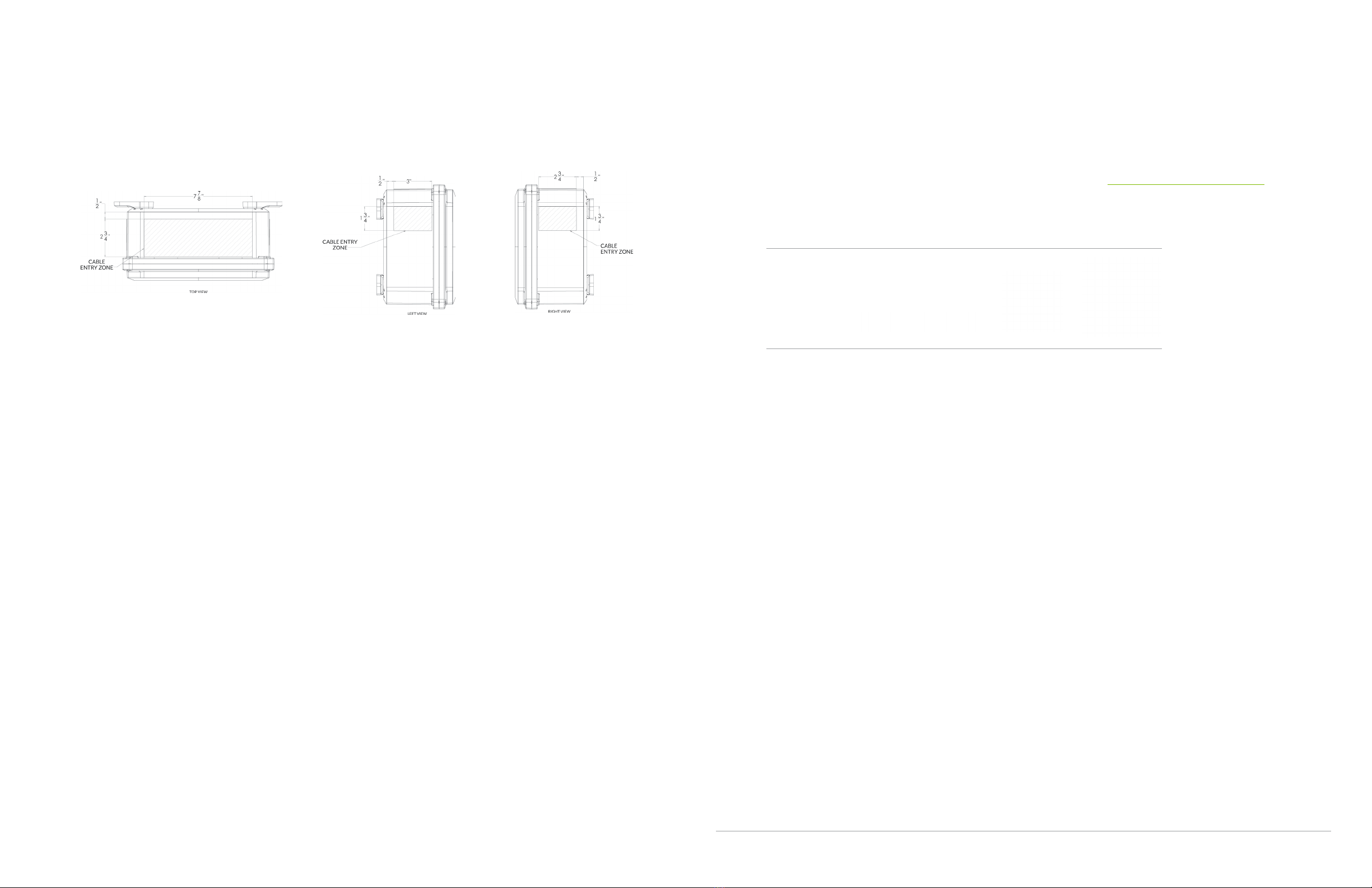
Gateway Enclosure Conduit Entry Points
1. Entry points for cabling should be drilled into the flat surface plane on the top of the gateway enclosure and/or the upper sides of the
gateway enclosure. Use the visual diagrams in this section for more specific guidance on proper entry point locations.
2. It is recommended to drill the fewest possible entry points to accommodate the required cabling based on the specific installation.
3. Use the appropriate conduit fittings for the installation to maintain the outdoor rating per local AHJ (authority having jurisdiction).
Wiring Install Instructions
4. Connect GW-1 to the RJ45 port labeled BMS on the SimpliPHI 6kW Inverter.
5. Connect one end of GW-8 to the RJ45 port on GW-1 and the other end to the RJ45 port labeled DEVICE on one of the SimpliPHI
4.9kWh Batteries. If there are multiple batteries installed in parallel, the installer can connect this to the port on any of the
batteries.
6. Connect the 3 position connector on GW-2 to the CAN port on the EnergyTrak Gateway.
7. Connect one end of GW-10 to the RJ45 port on GW-2 and the other end to one of the two open RJ45 ports labeled BATTERY on
the battery bank. An available RJ45 terminator should be installed in the other open RJ45 port labeled BATTERY on the battery
bank.
8. Connect GW-3 to GW-6 using the DB9 connectors.
9. Connect GW-6 to any of the four open USB ports on the EnergyTrak Gateway.
10. Connect one end of GW-9 to GW-3 and the other end to the RJ45 port labeled RS-232 on the SimpliPHI 6kW Inverter.
11. Connect the 2 position connector on GW-4 to the POWER port on the EnergyTrak Gateway.
12. Connect the black wire on GW-4 to the -Vin port on the DC-DC power supply unit.
13. Connect the red wire on GW-4 to the +Vin port on the DC-DC power supply unit.
14. Connect one end of GW-11 to the ETHERNET port on the EnergyTrak Gateway and the other end to an open port on the site’s
network switch or router (customer owned). NOTE: Verify with the site owner that the port on the site’s network switch or router
can provide Internet access to the Gateway. This step is optional if using WiFi to connect the EnergyTrak Gateway to the Internet.
15. Ensure GW-5 is securely installed between the fuse terminal block and the DC-DC power supply unit. This wire was pre-installed
prior to shipping.
16. Connect GW-7 ring terminals onto the GW-12 electrical wires. It is recommended to use one red wire and one black wire for easy
identification of the DC circuit.
17. Connect the red electrical wire assembly to the positive power terminal on the SimpliPHI 4.9kWh Battery using the GW-7 ring
terminal, and connect the other end to the 3A Fuse Terminal Block.
18. Connect the black electrical wire assembly to the negative power terminal on the SimpliPHI 4.9kWh Battery using the GW-7 ring
terminal, and connect the other end to the -Vo port on the DC-DC power supply unit.
Once the SimpliPHI ESS and EnergyTrak Gateway installations are complete, proceed with setup in the EnergyTrak app.
Review the following section for guidance on using EnergyTrak.
>>>
EnergyTrak
Briggs & Stratton
EnergyTrak for Pros
ENERGYTRAK USER MANUAL | 9

ENERGYTRAK USER MANUAL | 10
Site Fleet Tracking
Pro users can monitor the status of their customer sites from the Sites screen in the EnergyTrak app.
Each site has a status that indicates its current operating state, including:
Healthy: All systems are functional and normal
Warning: Some non-essential systems have been lost, but no reported critical failures
Critical: Essential failures with a system have been detected
Ready for Setup: The site has been created but no products have been set up
Deactivated: Site has been unregistered from the EnergyTrak platform
The Sites screen is also where Pro users can create new Sites for new installations.
Site Dashboard
The Site Dashboard will show a summarized view of the site’s connected product, the systems
related to the configuration, and the EnergyTrak Gateway.
From this screen, Pro users are able to view greater detail about and remotely edit the
configuration of the installed products for any site registered to their account.
For safety reasons, System Owner users are not able to edit the configuration of the ESS, but they
do have the ability to edit network settings of the EnergyTrak Gateway (i.e., WiFi network settings)
and toggle the time-of-use (TOU) settings OFF/ON. An owner may want to temporarily turn o
TOU settings if they expect a disruption to their grid power availability (i.e., encroaching storm)
and prefer to reserve the stored battery power for backup needs.
Change Configuration
The Change Configuration feature allows users to adjust settings at a specific Site related to En-
ergyTrak and the connected products. This capability can be accessed from the Change Configu-
ration button found on the Site Dashboard. A particular user can only access this feature on sites
which they are registered to.
ENERGYTRAK USER MANUAL | 11

ENERGYTRAK USER MANUAL | 12
SimpliPHI ESS
Commissioning
with EnergyTrak
Before You Start
There are several preparations and pieces
of information to collect before you start
commissioning the SimpliPHI ESS from the
EnergyTrak app.
SimpliPHI ESS Install
Ensure your SimpliPHI ESS has been properly
installed as outlined in the SimpliPHI 6kW Inverter
Installation Manual and SimpliPHI 4.9kWh
Installation Manual.
Gateway Install
Ensure the EnergyTrak Gateway has been installed properly as outlined in the section above titled
EnergyTrak Gateway Installation.
WiFi Info (optional)
If using a WiFi network connection to connect the EnergyTrak Gateway to the Internet, confirm the WiFi
network credentials (network name/SSID and password) for the site’s network.
WARNING: An unreliable wireless network connection can disrupt timely firmware
updates, which could lead to critical system failures. Therefore, Briggs & Stratton does
not recommend the use of a wireless connection.
Gateway Proximity
Ensure you are within Bluetooth range (10 feet) of the EnergyTrak Gateway.
Grid Profile
Confirm the appropriate “Grid Profile” that should be set in the SimpliPHI 6kW Inverter based on the
installation. Options include IEEE 1547 Default or O-Grid.
Operating Profile
Confirm the appropriate “Operating Profile” that should be set in the SimpliPHI 6kW Inverter based on
the installation. See the section below titled Choose Operating Profile for more details.
Site Info
The SimpliPHI ESS will be registered to a Site within EnergyTrak. To create a new site, you will need:
• Site name
• Street address
• City
• State
• Zip code
A new Site can be created at any time prior to commissioning the system.
System Owner Info
Towards the end of commissioning, you can optionally create a System Owner user account to help
simplify the owner’s use of EnergyTrak and their new SimpliPHI ESS (recommended). Confirm the
owner’s full name, email address, and phone number in order to complete this.
Mobile Device Battery Level
To ensure the commissioning process is not interrupted, ensure the mobile device being used to
perform commissioning in the EnergyTrak app has at least 50% battery level.
SimpliPHI 4.9kWh Battery Charge Level
Ensure that the connected battery (or batteries) have at least a 30% charge level (SoC) prior to
beginning. This ensures that critical processes are not interrupted due to a loss of power.
ENERGYTRAK USER MANUAL | 13

ENERGYTRAK USER MANUAL | 14
Create a New Site
To create a new Site, navigate to the Sites list and press the CREATE NEW SITE button at the bottom of
the screen.
More information: Before you are able to commission the SimpliPHI ESS using the EnergyTrak app,
you will first need to create a new Site in the app. A Site represents the physical location where the
product is being installed (typically, a residence or a business).
Start Commissioning
Before you are able to commission the SimpliPHI ESS using the EnergyTrak app, you will first need
to create a new Site in the app. A Site represents the physical location where the product is being
installed (typically, a residence or a business).
Establish Power to the Inverter
Before continuing further, establish power to the inverter (and turn on the batteries, if applicable) at
this time.
The app provides an abbreviated walkthrough on how to do this. However, technicians who are new
to the SimpliPHI ESS are encouraged to review the more detailed guide provided in the SimpliPHI
6kW Inverter Installation Manual and SimpliPHI 4.9kWh Installation Manual. This walkthrough can
optionally be skipped by clicking the SKIP THE INSTRUCTION button.
Connect to Gateway over Bluetooth
Select the appropriate Bluetooth network from the list for the EnergyTrak Gateway that was installed,
and then press the CONTINUE button. If prompted by the mobile device, be sure to allow both the
Bluetooth connection and location services.
More information: EnergyTrak uses a Bluetooth connection between the EnergyTrak Gateway and
the mobile device running the EnergyTrak app. The Bluetooth list will show all available Bluetooth
networks that are in range of the mobile device. The name of the gateway’s Bluetooth network
matches its ID#, which is printed on the label of the gateway.
If the EnergyTrak Gateway is not in the network list…
For security reasons, the EnergyTrak Gateway is designed to limit the length of time it remains in
pairing mode. The gateway will enter pairing mode for five (5) minutes after it powers ON. After
this period of time elapses, the gateway will need to be power cycled in order to force it back into
pairing mode.
To power cycle the gateway, simply unplug its power cable for 20 seconds and then plug it back
in. After about one (1) minute, the gateway will enter Bluetooth pairing mode and broadcast its
presence to the app.
If you are already on the “Connect to gateway” screen in the app, you can remain on this screen
to see it refresh automatically once the network is detected. If the list does not refresh within one
(1) minute of power cycling the gateway, go back to the previous screen and then advance to the
Connect to gateway screen again to force this list to refresh.
Once a mobile device has been paired with an EnergyTrak Gateway, it will retain this device in
its memory and connect automatically when the device is in range. The gateway does NOT need
to remain in pairing mode throughout the commissioning process; once connected to a mobile
device, it will maintain its connection as long as the mobile device remains in range.
ENERGYTRAK USER MANUAL | 15

ENERGYTRAK USER MANUAL | 16
Equipment Details
Ensure the proper inverter and battery quantities are detected.
More information: The EnergyTrak Gateway will automatically search for and detect the compatible equipment
which is (a) powered ON and (b) properly connected to the gateway. The Equipment Details screen will show the
SimpliPHI 6kW Inverter and SimpliPHI 4.9kWh Battery (or Batteries) it is able to detect.
Update Firmware
If the firmware files on the inverter or battery are up-to-date, press the CONTINUE button (it will be the only
button shown).
If the firmware files on the inverter or battery need to be updated, press the UPDATE FIRMWARE button (it
will be the only button shown) to begin the update process.
More information: The EnergyTrak mobile app stores and maintains the current firmware files for
the SimpliPHI 6kW Inverter and SimpliPHI 4.9kWh Battery. When the Equipment details screen opens,
EnergyTrak will automatically check the current version of the firmware files in the app with the version of the
firmware files currently installed on the inverter and battery.
Firmware File Transfer to Gateway
The mobile app will first transfer the firmware files from the mobile device to the gateway using the Bluetooth
connection. Please allow up to two minutes for the transfer to be completed. BE SURE TO REMAIN IN
BLUETOOTH RANGE UNTIL THIS IS COMPLETED.
Firmware Update to Inverter and Battery
Once the files have been transferred to the gateway, updating of the inverter and battery will begin using the
hardwired connection between the gateway and the devices. This process can take upwards of 20 minutes
or more to complete. This process is NOT reliant on the Bluetooth connection between the mobile device and
the gateway, so it is okay to take the mobile device out of Bluetooth range (go get a snack!).
If the mobile device leaves Bluetooth range once the gateway has begun updating the firmware on the
inverter and/or battery, the firmware update process will continue between the EnergyTrak Gateway and the
SimpliPHI ESS).
Press the CONTINUE button once the firmware files are up to date.
Choose Grid Profile
Select the appropriate Grid Profile and then press the CONTINUE button.
More information: The “Grid Profile” is a selection made during commissioning the SimpliPHI ESS
in EnergyTrak which defines specific operating parameters of the SimpliPHI 6kW Inverter, ensuring the
system is compliant and interoperable with the site’s electric utility. Select either IEEE 1547 Default or
O-Grid, depending on the application.
Choose Operating Profile
Select the appropriate Operating Profile and then press the CHOOSE PROFILE button.
More information: The “Operating Profile” is a selection made during commissioning the SimpliPHI
ESS in EnergyTrak which acts like an “easy button” for getting the system online. Each operating profile
has a pre-defined template of settings that are applied to the SimpliPHI 6kW Inverter. Most of these
settings can be customized prior to completing the commissioning process. See the section below for
more information related to Operating Profiles.
If you select the Grid-Tied Backup profile, you will be prompted to optionally define the desired time-
of-use settings. Follow the on-screen instructions to complete this section.
Note: If you selected the O-Grid Grid Profile in the previous menu, then the system will default to the
O-Grid Operating Profile and you will skip this step.
ENERGYTRAK USER MANUAL | 17

ENERGYTRAK USER MANUAL | 18
Operating Profile Descriptions
Grid-Tied Backup
Parameter Setting
Solar Distribution Priority Battery > Load > Grid
Enable Charging Enabled
Enable AC Charging Enabled
Enable feed to Utility Enabled
Enable discharge to Load when PV present Disabled
Enable discharge to Load when PV absent Disabled
Grid-Tied Backup with Time-of-Use
Parameter Setting
Solar Distribution Priority: On-Peak Load > Battery > Grid
Solar Distribution Priority: O-Peak Battery > Load > Grid
Enable Charging Enabled
Enable AC Charging Enabled
Enable feed to Utility Disabled
Enable discharge to Load when PV present Enabled
Enable discharge to Load when PV absent Enabled
Grid-Tied Zero Export
Parameter Setting
Solar Distribution Priority Load > Battery
Enable Charging Enabled
Enable AC Charging Enabled
Enable feed to Utility Disabled
Enable discharge to Load when PV present Enabled
Enable discharge to Load when PV absent Enabled
Grid-Tied Solar
Parameter Setting
Solar Distribution Priority Grid
Enable Charging Disabled
Enable AC Charging Disabled
Enable feed to Utility Enabled
Enable discharge to Load when PV present Disabled
Enable discharge to Load when PV absent Disabled
O-Grid
Parameter Setting
Solar Distribution Priority Load > Battery
Enable Charging Enabled
Enable AC Charging Disabled
Enable feed to Utility Disabled
Enable discharge to Load when PV present Enabled
Enable discharge to Load when PV absent Enabled
ENERGYTRAK USER MANUAL | 19

ENERGYTRAK USER MANUAL | 20
Summary and Edit Configuration
Review the listed settings on the Summary screen and verify these are the correct settings to apply
to the inverter.
When the configuration parameters for the SimpliPHI ESS are ready to be set, press the DONE
button to continue with the EnergyTrak setup.
More information: The summary screen will show a high-level view of the settings which will be
applied to the SimpliPHI 6kW Inverter once complete. If you would like to change any of the inverter’s
parameters, press the corresponding EDIT button for configuration options within that section. See
the following section of this manual titled Edit Configuration Details for more information.
Note: Only a select subset of the SimpliPHI 6kW Inverter configuration parameters are available
in EnergyTrak. The “source of truth” for these settings resides in EnergyTrak, and changes made to
these settings outside of EnergyTrak (i.e., from the front panel on the inverter) will be overwritten.
It is important to only change these settings within the EnergyTrak app. See the complete list of
EnergyTrak settings below.
To change settings which are not available in EnergyTrak, you will need to use the LCD panel on the
front of the inverter. Refer to the SimpliPHI 6kW Inverter Installation Manual and SimpliPHI 4.9kWh
Installation Manual for more information.
EnergyTrak SimpliPHI 6kW Inverter Settings
• Grid Profile
• Max Charge Current
• Max AC Charge Current
• Bulk Charge Voltage
• Float Charge Voltage
• LBCO When Grid is Available
• LBCO When Grid is Unavailable
• Max Discharge Current in Hybrid Mode
• Battery Ok to Discharge When Grid is Unavailable
• Frequency
• Grid Monitoring/Reconnect Time
• Max Power to Grid
• Load Output
• Generator as Power Source
• Buzzer/Alarm
• Mute Alarm in Standby Mode
• System Date
• System Time
• Solar Distribution Priority
• Enable Charging
• Enable AC Charging
• Enable feed to Utility
• Enable discharge to Load when PV present
• Enable discharge to Load when PV absent
• AC Charge Time Window
• AC Support Load Time Window
Add System Owner
Enter the required information for the System Owner and press the ADD button. This will create a
new EnergyTrak System Owner user account.
More information: If the email address is NOT associated with an existing EnergyTrak account,
recommended to confirm that the customer received the email before completing the job.
If the email address is already associated with an EnergyTrak account, you must skip this step and
add the System Owner from the Site Dashboard screen once commissioning is complete.
Even though this is an optional step during the commissioning process, adding a system owner
to the site must be completed before the owner can associate the SimpliPHI ESS with their
EnergyTrak account and see it in the EnergyTrak app.
Connect Gateway to the Internet
If the EnergyTrak Gateway has already been connected to the Internet using a hardwired Ethernet
cable connection, then this step can be skipped. Optionally, the WiFi network connection can also
be set up as a redundant connection to the Ethernet connection.
If using WiFi as the primary network for the Internet connection (NOT RECOMMENDED), this step
should NOT be skipped.
To set up the WiFi network connection, select the appropriate WiFi network from the list, press
CONNECT, enter the network’s password, and then press the JOIN button.
Note: EnergyTrak requires an Internet connection to operate. Establishing an Internet connection
to the EnergyTrak Gateway does rely on the site’s local network and its Internet connection. This
requires the system owner to provide and maintain a healthy, reliable network and Internet connection
for EnergyTrak. See the section above titled Site Network and Internet Requirements for specific
requirements.
WARNING: An unreliable wireless network connection can disrupt timely firmware updates, which
could lead to critical system failures. Therefore, Briggs & Stratton does not recommend the use of a
wireless connection.
ENERGYTRAK USER MANUAL | 21

ENERGYTRAK USER MANUAL | 22
Setup Confirmation
Setup complete! At this time, the EnergyTrak Gateway should be connected to the Internet, and the
SimpliPHI ESS should be working as configured.
The site should be viewable from the Sites screen in the EnergyTrak app, and the status of the site should
be HEALTHY unless something needs to be addressed. Selecting the site will show the Site Dashboard
with a detailed view of the current power flow through the SimpliPHI ESS.
The Site Dashboard and Change Configuration features can be used to view and validate the settings
which have been applied to the system, including details about the SimpliPHI ESS. Pros are highly
encouraged to review this detail and validate the system’s operation prior to completing their work.
Troubleshooting
At this point, if the SimpliPHI ESS is producing any faults, or the system is not operating as intended, the
technician should troubleshoot the system using the self-help resources available. Technical Support
from Briggs & Stratton is also available to assist technicians with troubleshooting. The Help screen in
the EnergyTrak app (found in the primary menu) includes links to resources and contact information for
Technical Support, if needed.
This manual suits for next models
7
Table of contents
Popular Storage manuals by other brands

Norcent
Norcent SDT-1GB UPC # TBD Specification sheet

Quantum
Quantum DAT 320 CD320UE quick start guide

Storehouse
Storehouse 97563 Assembly, operating, and maintenance instructions

Quantum
Quantum FastStor 1 user guide

Symantec
Symantec NetBackup 5230 Maintenance Guide

Western Digital
Western Digital WD2503ABYZ Specifications