P/N 760-0000331 Rev C December 2005 Page 1
000331c.doc 18-Dec-05 2:30 PM
BroadAccess
Installation Instructions
PSBC12XX Charger
Description
The PSBC12XX charger is a power supply unit installed in outdoor/indoor
cabinets or standard 19” racks, which is used for charging batteries and powering
equipment directly. Overcurrent and overvoltage protection is provided to prevent
damage that might be caused by a faulty battery and/or external load. Temperature
compensation is employed to enhance battery life.
The PSBC12XX charger supports battery sets, which are charged as long as AC
power is on. When AC power is off, the batteries supply current directly to the
load.
If alarm monitoring, event logs or detailed PSBC12XX charger parameters are
required, the PSM1006 GUI software supplied with the PSBC12XX charger can
be installed on a PC which connects to the PSBC12XX charger controller. For
more information, refer to the BroadAccess PSBC 12XX-X Charger Management
Software User Guide.
Table 1. PSBC12XX Charger - Features
Power
Supply
(VDC)
Max No. of
Rectifiers Battery Sets
Supported Input
Voltage
(VAC)
Output
Voltage
(VDC)
Current Output Per
Rectifier Module
48 5 285-275 54 12A at 230 Vac input
Compatibility
The PSBC12XX charger is suitable for use with BroadAccess systems Ver 40
Release 3.0 and higher, or cabinets adapted for this charger.
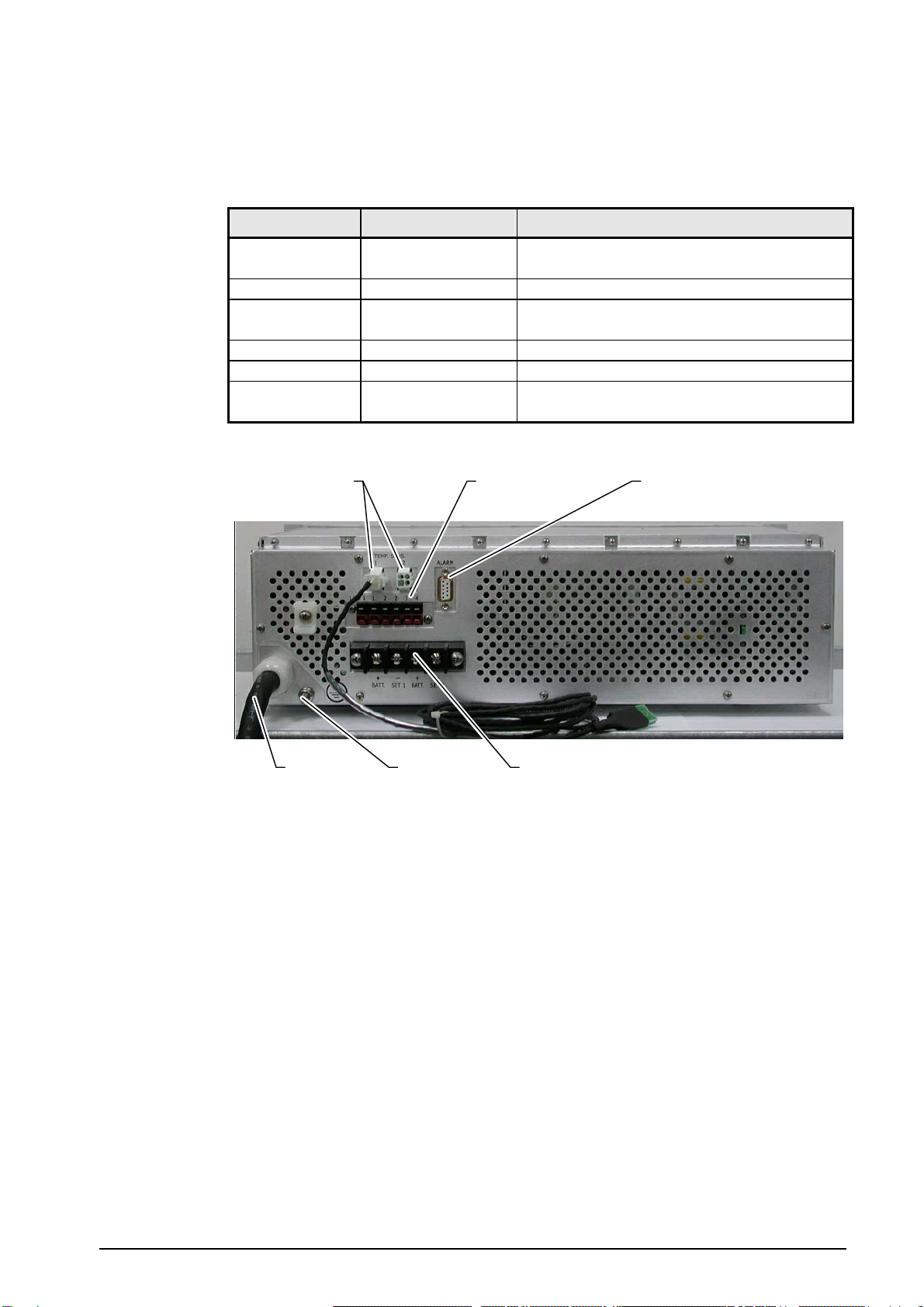
Charger Controls and Indicators
PSBC12XX charger front panel controls and indicators are shown in Figure 1 and
described in Table 2.
Table 2. Front Panel Components
Designation Description Function
Mounting
Brackets - Enables mounting of chargers in cabinets and racks
Rectifier
Modules 1 to 5
rectifiers Convert AC power to DC power. The modules operate in
parallel in “N+1” configuration. Each rectifier supplies
12A/600W. The rectifiers are capable of load sharing.