Brotech RH-9820 User manual

RH-9820
上糸つかみ装置
この説明書を読んでから、製品をご使用ください。
この説明書は、必要なときにすぐに取り出せる場所に、保管してください。
UPPER THREAD NIPPER DEVICE SET
Please read this manual before using the machine.
Please keep this manual within easy reach for quick reference.
面线夹线装置
在使用本装置之前请先阅读该装置的使用说明书。
请将本使用说明书放在便于查阅的地方保管。
PINZA DE HILO SUPERIOR
Por favor lea este manual antes de usar la máquina.
Por favor guarde este manual al alcance de la mano para una rápida referencia.
取扱説明書
INSTRUCTION MANUAL
使用说明书
MANUAL DE INSTRUCCIONES

目次
1. 仕様 ··························································· 1
2. 取り付け方 ················································ 2
2-1. バルブユニットの取り付け方 ···························3
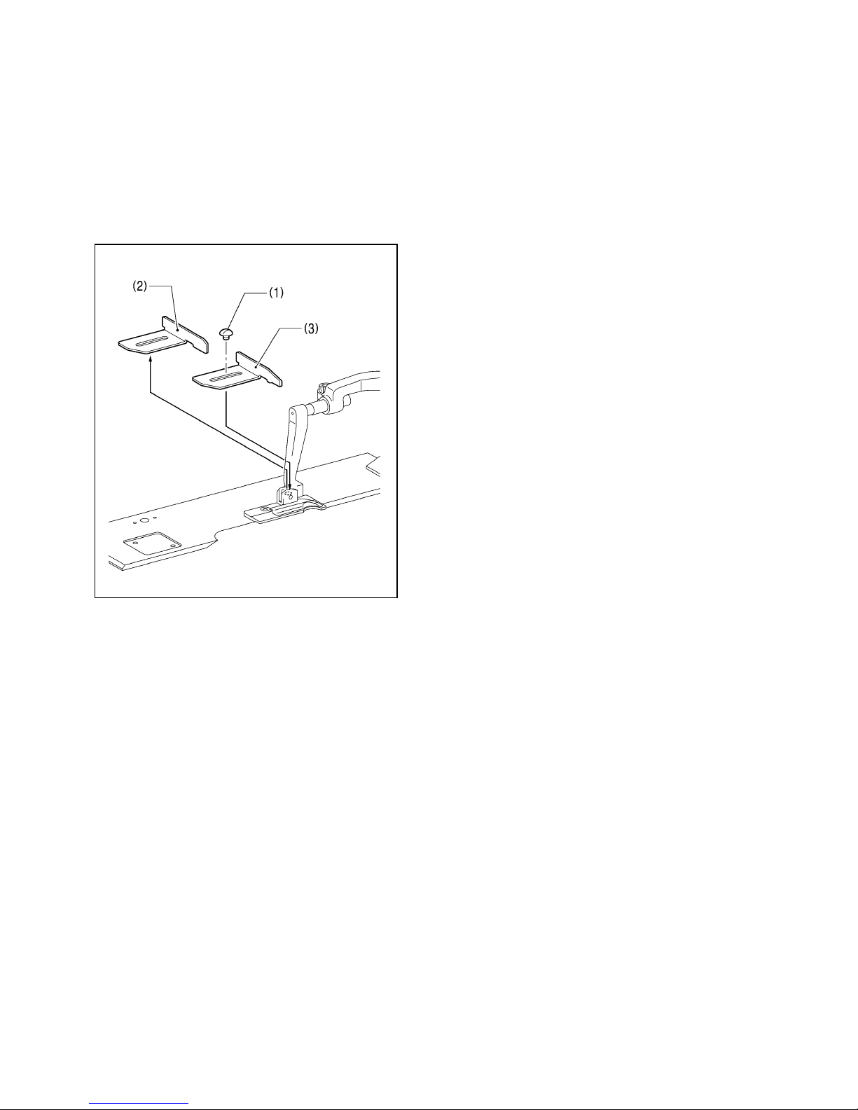
2-2. 布ガイドの交換 ················································4
2-3. 上糸つかみ装置本体の取り付け方····················5
2-4. エアーチューブの配線······································6
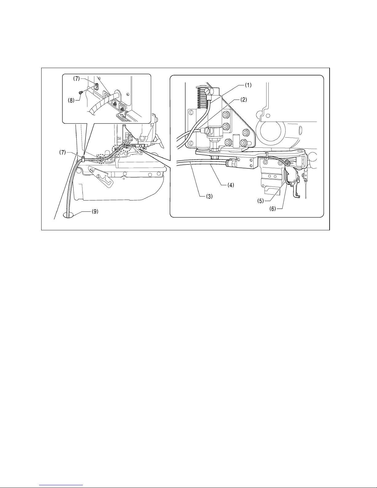
2-5. エアーチューブの接続······································7
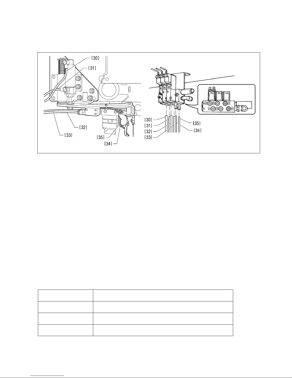
2-6. バルブハーネスの接続······································8
2-7. エアーチューブ、ハーネスの固定··················12
3. 上糸つかみ装置に関する設定·················· 13
4. 標準調整·················································· 15
4-1. 糸つかみの左右位置調整 ································15
4-2. 糸つかみの上下位置調整 ································17
4-3. 糸つかみの上下移動速度の調整 ·····················18
4-4. 上糸繰り出し量の調整····································19
5. パーツリスト··········································· 20
目 录
1. 规格 ··························································· 1
2. 安装方法···················································· 2
2-1. 阀门组的安装法 ················································3
2-2. 布料导向的交换 ················································4
2-3. 面线夹线装置本体的安装法·······························5
2-4. 空气接管的配线 ················································6
2-5. 空气接管的接续 ················································7
2-6. 阀门组电线的接续·············································8
2-7. 空气接管,电线的固定····································12
3. 有关面线夹线装置的设定························· 13
4. 标准调整·················································· 15
4-1. 线夹左右位置的调整 ·······································15
4-2. 线夹上下位置的调整 ·······································17
4-3. 线夹的上下移动速度的调整·····························18
4-4. 面线放出量的调整···········································19
5. 零部件清单 ·············································· 20
CONTENTS
1. Specifications ··········································1
2. Installation················································ 2
2-1. Installing the valve unit····································· 3
2-2. Replacing the cloth guides ······························· 4
2-3. Installing the upper thread nipper unit ·············· 5
2-4. Routing the air tubes ········································ 6
2-5. Connecting the air tubes ·································· 7
2-6. Connecting the valve harness·························· 8
2-7. Securing the air tubes and harnesses············ 12
3. Upper thread nipper settings ···············13
4. Standard adjustments··························· 15
4-1. Adjusting the sideways position of the thread
nipper ····························································· 15
4-2. Adjusting the vertical position of the thread
nipper ····························································· 17
4-3. Adjusting the vertical movement speed
of the thread nipper ········································ 18
4-4. Adjusting the upper thread feeding amount ··· 19
5. Parts list ················································· 20
CONTENIDO
1. Especificaciones ·····································1
2. Instalación················································2
2-1. Instalación del unidad de válvula ····················· 3
2-2. Volviendo a colocar las guías de tejido ············ 4
2-3. Instalación de la unidad de la pinza de hilo
superior ···························································· 5
2-4. Ruteando los tubos de aire ······························ 6
2-5. Conexión de los tubos de aire·························· 7
2-6. Conexión del mazo de conductores
de válvula························································· 8
2-7. Asegurando los tubos de aire y los mazos de
conductores ··················································· 12
3. Ajustes de pinza de hilo superior ········13
4. Ajustes estandares································ 15
4-1. Ajuste de la posición lateral de la pinza
de hilo ···························································· 15
4-2. Ajuste de la posición vertical de la pinza
de hilo ···························································· 17
4-3. Ajuste de la velocidad de movimiento vertical
de la pinza de hilo ·········································· 18
4-4. Ajuste de la alimentación de hilo superior······ 19
5. Lista de partes ······································· 20

RH-9820 UPPER THREAD NIPPER DEVICE SET 1
仕様/Specifications
规格/Especificaciones
縫い長さ
42mm を超える縫い長さにはご使用いただけません。
* 縫い長さが 22mm 以下の場合、上糸端がうまく縫い目の中に巻き込まれないことがあります。
この場合、縫製後にはみ出した上糸の端を切り取る必要があります。
上糸つかみ装置をミシンに取り付けたままで無効にするには
メモリースイッチモードにて、上糸つかみ装置の使用を“OFF”に設定してください。(「3.上糸つかみ装置に関する設定」参
照)
Sewing length
The upper thread nipper cannot be used if the sewing length exceeds 42 mm.
* If the sewing length is 22 mm or less, the end of the upper thread may not be wound properly into the stitches.
In such cases, it will be necessary to trim the ends of the upper thread that protrude after sewing is finished.
Deactivating the upper thread nipper while leaving it installed to the sewing machine
In memory switch mode, change the setting for using the upper thread nipper to “OFF”. (Refer to “3. Upper thread nipper
settings”.)
锁缝长度
超过 42mm 以上的长度不能使用。
* 锁缝长度在 22mm 以下时,面线的线头有可能不能很好的被卷入到锁缝中去。
出现该情况时,缝纫完了后,必须将面线的线头剪去。
只将面线夹线装置安装在缝纫机上是无效的
在存储开关模式中,请将面线夹线装置的使用设定为“OFF”。(参考「3. 有关面线夹线装置的设定」)
Largo de costura
La pinza de hilo superior no se puede usar si el largo de costura excede 42 mm.
* Si el largo de costura es 22 mm o menos, el extremo del hilo superior podría no enrollarse correctamente en las
puntadas.
En esos casos, será necesario cortar los extremos del hilo superior que sobresale después de terminar la costura.
Desactivando la pinza de hilo superior dejándola instalada en la máquina de coser
En el modo de interruptor de memoria, cambie el ajuste para usar la pinza de hilo superior en “OFF”. (Consulte la sección
“3. Ajustes de pinza de hilo superior”.)
1

RH-9820 UPPER THREAD NIPPER DEVICE SET
2
取り付け方/Installation
安装方法/Instalación
危険/DANGER/危险/PELIGRO
コントロールボックスのカバーを開ける時は必ず電源スイッチを切り、電源プラグを抜いて、その後
5 分間待ってからカバーを開けてください。高電圧部分にふれると、大けがをすることがあります。
Wait at least 5 minutes after turning off the power switch and disconnecting the power cord from the wall
outlet before opening the cover of the control box. Touching areas where high voltages are present can
result in severe injury.
在关闭电源开关并将电源插头从插座上拔下后,至少等待 5 分钟,再打开控制箱盖。
触摸带有高电压的区域将会造成人员伤亡。
Después de desconectar el interruptor principal y desenchufar el cable de alimentación del
tomacorriente en la pared esperar al menos 5 minutos antes de abrir la cubierta de la caja de controles.
El tocar las áreas donde exista alto voltaje puede ocasionar heridas graves.
注意/CAUTION/注意/ATENCION
作業の前に電源スイッチを切り、電源プラグを抜いてください。
誤ってスタートスイッチを押すと、ミシンが作動してけがの原因となります。
エアー供給源のエアーコックを閉じ、ドレインコックよりエアーを抜き、圧力計の指針を「0」にして
ください。
Turn off the power switch and disconnect the power cord before carrying out this operation. If this is not
done, the sewing machine may operate if the start switch is pressed by mistake, which could result in
serious injury.
Close the air cock of the air supply source, and then open the drain cock to bleed the air until the needle
of the pressure gauge points to “0”.
作业前请先关闭电源开关,并将电源插头从插座上拔下。
当误按启动开关时,缝纫机动作会导致人员受伤。
请先关闭气源开关,然后从排放栓中将余气排放出,并等压力表指针下降到 「0」为止。
Desconectar el interruptor principal y desconectar el cable de alimentación antes de comenzar esta
operación. De lo contrario, la máquina de coser podría comenzar a funcionar si por descuido se
accionara el interruptor de arranque, lo que podría resultar en heridas graves.
Cierre el grifo de aire de la alimentación de aire, y luego abra el grifo de drenaje para purgar el aire
hasta que la aguja del indicador de presión apunte a “0”.
2

RH-9820 UPPER THREAD NIPPER DEVICE SET 3
2-1. バルブユニットの取り付け方
2-1. Installing the valve unit
2-1. 阀门组的安装法
2-1. Instalación del unidad de válvula
1. バルブユニット(1)のNo.34 とNo.35 の穴に、レジューサ(2)[2
本]を差し込みます。
2. バルブユニット(1)をエアーユニット(3)の横に、木ねじ(4) [2
本]で取り付けます。
* 他の部品のじゃまにならない位置に取り付けてください。
1. Insert the two reducers (2) into holes No.34 and No.35 in
the valve unit (1).
2. Install the valve unit (1) to the side of the air unit (3) with the
two screws (4).
* Install the valve unit in a position where it will not obstruct
any other parts.
1. 在阀门组(1)的No.34 和No.35 的孔处,插入变径销(2)[2 个]。
2. 在空压装置(3)的旁边用木螺钉(4)[2 个]将阀门组(1)固定。
* 请安装在不妨碍别的零部件的位置。
1. Inserte las dos tapas (2) en los agujeros No.34 y No.35 en
la unidad de válvula (1).
2. Instale la unidad de válvula (1) a un costado de la unidad
neumática (3) con los dos tornillos (4).
* Instale la unidad de válvula en una posición donde no
obstruya ninguna otra parte.
バルブユニット(1)の[A]へ
To [A] of valve unit (1)
连接到阀门组(1)的[A]上
[A] de la unidad de válvula (1)
3. エアーユニット(3)からエアーチューブ(5)を取り外します。
4. 継ぎ手(6)を使用し、エアーチューブ(5)、(7)、(8)を図のように接続します。
3. Disconnect the air tube (5) from the air unit (3).
4. Use the joint (6) to connect the air tubes (5), (7) and (8) as shown in the illustration.
3. 将空压装置(3)从空气接管(5)处取下。
4. 使用管接头(6),如图所示,连接空气接管(5),(7),(8)。
3. Desconecte el tubo de aire (5) de la unidad neumática (3).
4. Use la unión (6) para conectar los tubos de aire (5), (7) y (8) tal como se indica en la figura.
0572B
0945B

RH-9820 UPPER THREAD NIPPER DEVICE SET
4
2-2. 布ガイドの交換
2-2. Replacing the cloth guides
2-2. 布料导向的交换
2-2. Volviendo a colocar las guías de tejido
* 下記は、左側の布ガイドの交換を説明したものです。右側の布ガイドも同様に交換してください。
* The following steps explain how to replace the left cloth guide. Replace the right cloth guide in the same way.
* 以下是对左侧的布料导向的交换进行说明。请按同样的方法对右侧的布料导向进行交换。
* Los siguientes pasos explican como volver a colocar la guía de tejido izquierda. Vuelva a colocar la guía de tejido derecha
de la misma manera.
1. 締ねじ(1)を外して、布ガイド L(2)を取り外します。
2. 付属の布ガイド L(3)を取り付け、締ねじ(1)で固定します。
1. Remove the screw (1), and then remove cloth guide L (2).
2. Install the accessory cloth guide L (3) and then secure it
with the screw (1).
1. 旋下螺钉(1),取出布料导向 L(2)。
2. 安装附件中的布料导向 L(3),使用螺钉(1)将其固定。
1. Quite el tornillo (1) y a continuación retire la guía de tejidos
L (2).
2. Instale la guía de tejido accesoria (3) y a continuación
asegúrela con el tornillo (1).
0946B

RH-9820 UPPER THREAD NIPPER DEVICE SET 5
2-3. 上糸つかみ装置本体の取り付け方
2-3. Installing the upper thread nipper unit
2-3. 面线夹线装置本体的安装法
2-3. Instalación de la unidad de la pinza de hilo superior
上糸つかみ総組(1)を矢印の方向に押さえつけ、穴ボルト(2)[3
本]を締め付けてアームの左側面に取り付けます。
* 糸つかみ(3)およびチューブ(4)が、ハンマー(5)に接触しない
ことを確認してください。
接触する場合は、穴ボルト(2)[3 本]をゆるめ、取り付け位置
を調節してください。
Push the upper thread nipper set (1) in the direction of the
arrow, and install it to the left side of the arm by tightening the
three bolts (2).
* Check that the thread nipper (3) and the tube (4) do not
touch the hammer (5).
If they do touch, loosen the three bolts (2) and adjust the
installation position.
将面线夹总组件(1)向箭头的方向推紧,使用螺栓(2)[3 个]将其安
装在机壳的左侧面。
* 请确认线夹(3)以及接管(4)有没有碰到气锤(5)。如有碰到时,
松开螺栓(2)[3 个],请调整安装位置。
Empuje el juego de pinza de hilo superior (1) en la dirección
de la flecha, e instálela del lado izquierdo del brazo apretando
los tres pernos (2).
* Verifique que la pinza de hilo (3) y el tubo (4) no toque el
martillo (5).
Si toca, afloje los tres pernos (2) y ajuste la posición de
instalación.
0947B

RH-9820 UPPER THREAD NIPPER DEVICE SET
6
2-4. エアーチューブの配線
2-4. Routing the air tubes
2-4. 空气接管的配线
2-4. Ruteando los tubos de aire
1. エアーチューブ(1)、(2)、(3)、(4)、(5)、(6)を図の位置でコードホルダ#8(7)に通し、締ねじ(8)で固定します。
2. エアーチューブ類をコード穴(9)に通します。
1. Pass the air tubes (1), (2), (3), (4), (5) and (6) through cord holder #8 (7) in the place shown in the illustration, and then
secure them by tightening the screw (8).
2. Pass the air tubes through the cord hole (9).
1. 空气接管(1),(2),(3),(4),(5),(6)在如图上所示的位置,通过线夹#8(7)后,使用螺钉(8)将其固定。
2. 然后,再将其穿过电线孔(9)。
1. Pase los tubos de aire (1), (2), (3), (4), (5) y (6) a través del soporte de cable #8 (7) en el lugar que se muestra en la
figura, y luego asegúrela apretando el tornillo (8).
2. Pase los tubos de aire a través del agujero del cable (9).
0949B

RH-9820 UPPER THREAD NIPPER DEVICE SET 7
2-5. エアーチューブの接続
2-5. Connecting the air tubes
2-5. 空气接管的接续
2-5. Conexión de los tubos de aire
エアーチューブには番号ラベルが付いています。
エアーチューブ[30]、[31]、[32]、[33]、[34]、[35]を、番号に合わせてバルブユニットの穴に差し込みます。
* エアーチューブが長すぎる場合は、適切な長さに切ってお使いください。チューブやハーネスが絡まるのを防止するため
です。
* バルブには[50]~[53]の表示もありますが、これはフライインデクサー装置取り付け用の表示です。
ここでは必要ありません。
The air tubes have numbered labels on them.
Insert air tubes [30], [31], [32], [33], [34] and [35] into the holes in the valve unit so that the numbers match.
* If the air tubes are too long, cut them to suitable lengths before using them. This will prevent the tubes and harnesses
from getting twisted.
* The valves are also indicated by [50] to [53], but these indications are used when the fly indexer is installed. They are not
needed at the present time.
空气接管均带有标签号
将空气接管[30],[31],[32],[33],[34],[35]插到阀门组上有着同样号码的孔中。
* 如果空气接管太长时,请剪成适当的长度后使用。主要是为了防止接管和电线的相互缠绕。
* 关于在阀门组上表示的[50]~[53]号码,这是安装引导装置时使用的,在这里没有关系。
Los tubos de aire tienen etiquetas de numeración.
Inserte los tubos de aire [30], [31], [32], [33], [34] y [35] en los agujeros en la unidad de válvula de manera que los números
coincidan.
* Si los tubos de aire son demasiado largos, córtelos a los largos adecuados antes de usarlos. Esto impedirá que los tubos
y los mazos de cables se enreden.
* Las válvulas también están indicadas por [50] a [53], pero estas indicaciones son usadas cuando el indizador de
braguetas está instalado. No son necesarios en el momento.
ラベル No./Label No.
标签号 No./No. de etiqueta
ソレノイドバルブの種類/Solenoid valve type
电磁阀的种类/Válvula de tipo solenoide
[30] [31] 上下シリンダ用/For vertical feeding cylinder
上下气缸用/Para el cilindro de alimentación vertical
[32] [33] 前後シリンダ用/ For forward/back feeding cylinder
前后气缸用/Para el cilindro de alimentación hacia adelante/atrás
[34] [35] 開閉シリンダ用/ For opening/closing cylinder
开关气缸用/Para abrir/cerrar el cilindro
0950B

RH-9820 UPPER THREAD NIPPER DEVICE SET
8
2-6. バルブハーネスの接続
2-6. Connecting the valve harness
2-6. 阀门组电线的接续
2-6. Conexión del mazo de conductores de válvula
上糸つかみバルブハーネス(1)には番号ラベルが付いています。
1. 上糸つかみバルブハーネス(1)のピンコネクタ[8]、[9]、[10]
を、番号に合わせてバルブユニット(2)のソレノイドバルブ
の穴に差し込みます。
* バルブには[11]~[13]の表示もありますが、これはフライ
インデクサー装置取り付け用の表示です。
ここでは必要ありません。
The thread nipper valve harness (1) has numbered labels on it.
1. Insert the pin connectors [8], [9] and [10] on the thread
nipper valve harness (1) into the holes in the solenoid
valves of the valve unit (2) so that the numbers match.
* The valves are also indicated by [11] to [13], but these
indications are used when the fly indexer is installed.
They are not needed at the present time.
面线夹线阀门电线(1)上带有标签号。
1. 将面线夹线阀门电线(1)上的 3个插头[8],[9],[10]插到阀门
组(2)上有着同样号码的孔中。
* 关于在阀门组上表示的[11]~[13]号码,这是安装引导装置
时使用的,在这里没有关系。
El mazo de conductores de válvula de pinza de hilos (1) tiene
etiquetas numeradas.
1. Inserte los conectores de clavijas [8], [9] y [10] en el mazo
de conductores de válvula de pinza de hilos (1) en los
agujeros de la válvula de solenoide de la unidad de válvula
(2) de modo que coincidan los números.
* Las válvulas también están indicadas por [11] a [13],
pero estas indicaciones son usadas cuando el indizador
de braguetas está instalado. No son necesarios en el
momento.
ラベル No./Label No.
标签号 No./No. de etiqueta
ソレノイドバルブの種類/Solenoid valve type
电磁阀的种类/Válvula de tipo solenoide
[8] 上下バルブ用/For vertical feeding valve
上下气缸用/Para la válvula de alimentación vertical
[9] 前後バルブ用/For forward/back feeding valve
前后气缸用/Para la válvula de alimentación hacia adelante/atrás
[10] 開閉バルブ用/For opening/closing valve
开关气缸用/Para abrir/cerrar la válvula
0951B

RH-9820 UPPER THREAD NIPPER DEVICE SET 9
2. 上糸つかみバルブハーネス(1)をコードホルダ 18N(3)と24N(4)に通して、コントロールボックス(5)の中に取り入れます。
3. コントロールボックス(5)の蓋を開けます。
2. Pass the thread nipper valve harness (1) through cord holder 18N (3) and cord holder 24N (4), and then pass it into the
control box (5).
3. Open the cover of the control box (5).
2. 将面线夹线阀门电线(1)通过线夹 18N(3)和线夹 24N(4)后,再穿入到控制箱(5)的孔中。
3. 打开控制箱(5)的盖。
2. Pase el mazo de conductores de válvula de pinza de hilos (1) a través del soporte de cable 18N (3) y el soporte de cable
24N (4), y luego páselo dentro de la caja de controles (5).
3. Abra la cubierta de la caja de controles (5).
0952B

RH-9820 UPPER THREAD NIPPER DEVICE SET
10
4. 上糸つかみバルブハーネス(1)をコードクランプ(6)に通します。
5. メイン基板上の P25 コネクタからハンマーバルブハーネスのコネクタ(7)を取り外し、上糸つかみバルブハーネス(1)のピ
ン[2]、[3]、[4]、[9]を番号に合わせてコネクタ(7)のピン穴に差し込みます。
6. コネクタ(7)をメイン基板上の P25 コネクタに接続します。
4. Pass the thread nipper valve harness (1) through the cord clamps (6).
5. Disconnect the connector (7) of the hammer valve harness from connector P25 on the main P.C. board, and then insert
pins [2], [3], [4] and [9] of the thread nipper valve harness (1) into the pin holes in the connector (7) so that the numbers
match.
6. Connect the connector (7) to connector P25 on the main P.C. board.
4. 将面线夹线阀门电线(1)通过电线夹(6)。
5. 从主基板上的 P25 插座上取下气锤阀门电线的插座(7)后,根据面线夹线阀门电线(1)的插头号码[2],[3],[4],[9]插到插座(7)
上有着同样号码的孔中。
6. 将插座(7)插到主基板上的 P25 插座上。
4. Pase el mazo de conductores de válvula de pinza de hilos (1) a través de las abrazaderas de cables (6).
5. Desconecte el conector (7) del mazo de conductores de válvula de martillo del conector P25 en el tablero P.C. principal,
y luego inserte las clavijas [2], [3], [4] y [9] del mazo de conductores de válvula del hilo (1) en los agujeros de clavijas en
el conector (7) de modo que coincidan los números.
6. Conecte el conector (7) al P25 en el tablero P.C. principal.
0953B

RH-9820 UPPER THREAD NIPPER DEVICE SET 11
7. ハーネスの接続と配線が全て完了したら、コントロールボッ
クス(5)の蓋を閉めます。
7. Once routing and connection of the harnesses are
complete, close the cover of the control box (5).
7. 电线类的接续和配线全部完了后,将控制箱(5)的盖关上。
7. Una vez que haya terminado con el ruteado y la conexión,
cierre la cubierta de la caja de controles (5).
0954B

RH-9820 UPPER THREAD NIPPER DEVICE SET
12
2-7. エアーチューブ、ハーネスの固定
2-7. Securing the air tubes and harnesses
2-7. 空气接管,电线的固定
2-7. Asegurando los tubos de aire y los mazos de conductores
エアーチューブとハーネスを、図に示す 6箇所に付属のユニタイバンド(1)[6 本]で固定します。
[ご注意]
ミシン頭部を倒したときに、エアーチューブとハーネスが引っ張られないように、余裕を持たせて配線してください。
Secure the air tubes and harnesses in six places using the six accessory bands (1) as shown in the illustrations.
[NOTE]
Route the air tubes and harnesses with enough slack so that they do not get pulled when the machine head is tilted back.
如图所示,在 6个地方使用附件电线夹(1)[6 个],将空气接管和电线进行固定。
[注意]
缝纫机头倒下时,空气接管和电线的配线均应带有余量,不可拉的过紧。
Asegure los tubos de aire y los mazos de conductores en seis lugares usando las seis bandas accesorias (1) tal como se
indica en las figuras.
[NOTA]
Rutee los tubos de aire y los mazos de conductores dejándolos lo suficientemente sueltos para que no queden estirados
cuando se incline la cabeza de la máquina.
0955B

RH-9820 UPPER THREAD NIPPER DEVICE SET 13
上糸つかみ装置に関する設定
Upper thread nipper settings
有关面线夹线装置的设定
Ajustes de pinza de hilo superior
上糸つかみ装置に関する設定は、操作パネルを使用し、必要なメモリースイッチ番号を呼び出して行ないます。
* メモリースイッチ番号“564”で上糸つかみ装置 ON(有効)/OFF(無効)の設定、“565”で上糸つかみの閉じタイミング補
正を行なうことができます。(設定方法は次ページ参照)
メモリー
スイッチ No. 設定値 内容 初期値
上糸つかみ装置の ON/OFF
OFF 上糸つかみ装置を無効にします
564
ON 上糸つかみ装置を有効にします
OFF
上糸つかみ閉じタイミング補正(mm)
565 -10~10 値を小さくすると通常よりも早く上糸をつかみます
値を大きくすると通常よりも遅く上糸をつかみます
0
Settings for the upper thread nipper are made using the operation panel by retrieving the required memory switch numbers.
* Memory switch No. 564 is used for the upper thread nipper ON (enabled)/OFF (disabled) setting, and No. 565 can be
used to correct the upper thread nipper closing timing. (Refer to the next page for the setting method.)
Memory switch
No.
Setting
value Setting items Default
value
Upper thread nipper ON/OFF
OFF Upper thread nipper is disabled.
564
ON Upper thread nipper is enabled.
OFF
Upper thread nipper closing timing correction (mm)
565 -10 - 10 If a smaller value is set, the upper thread is clamped earlier than normal.
If a larger value is set, the upper thread is clamped later than normal.
0
关于面线夹线装置的设定,使用操作盘来设定,叫出必要的存储开关号码 No。
* 用存储开关号码 No“564”上设定面线夹线装置 ON(有效)/OFF(无效),可以使用“565”进行面线夹的关闭时序的补正。(设
定方法请参阅下一页)
存储开关
号码(No.)设定值 内容 初始值
面线夹线装置的 ON/OFF
OFF 面线夹线装置无效
564
ON 面线夹线装置有效
OFF
面线夹的关闭时序的补正(mm)
565
-10~10 数值越小表示比通常时间早夹面线
数值越大表示比通常时间晚夹面线
0
Los ajustes para pinza de hilo superior son hechos usando el panel de control recuperando los números de interruptor de
memoria necesario.
* El interruptor de memoria No. 564 se usa para el ajuste de pinza de hilo superior ON (activada)/OFF (desactivada), y No.
565 se puede usar para corregir la sincronización de cierre de pinza de hilo superior. (Juego de dispositivo de pinza de
hilo.)
Interruptor de
memoria
número
Valor de
ajuste Items a ajustar Valor por
defecto
Pinza de hilo superior activada/desactivada
OFF Pinza de hilo superior desactivada.
564
ON Pinza de hilo superior activada.
OFF
Corrección de sincronización de cierre de pinza de hilo superior (mm)
565 -10 - 10
Si se ajusta un valor menor, el hilo superior será apretado antes de lo
normal.
Si se ajusta un valor mayor, el hilo superior será apretado después de lo
normal.
0
(次ページに続く)
(Continued on next page)
(下一页继续)
(Continúa en la página siguiente)
3

RH-9820 UPPER THREAD NIPPER DEVICE SET
14
設定のしかた/Setting method/设定方法/Método de ajuste
1. TEST キー(1)とPROGRAM キー(2)を押しながら、電源スイ
ッチの ON 側(3)を押します。
* 管理者用のメモリースイッチモードに入ります。
* 表示部の上段にメモリースイッチ番号(A)、下段に現在の
設定値(B)が表示されます。
2. △キーまたは▽キー(4)を押して、変更したいメモリースイ
ッチ番号を選択します。
1. While pressing the TEST key (1) and the PROGRAM key
(2), push the POWER switch at the ON side (3).
* The mode will switch to memory switch mode for
administrator.
* The memory switch number (A) will appear in the top
part of the display, and the setting value (B) for that
number will appear in the bottom part of the display.
2. Press the △or ▽key (4) to select the number for the
memory switch to be changed.
1. 在按下 TEST 键(1)和PROGRAM 键(2)的同时按下电源开关
(ON)侧(3)。
* 进入管理者用的存储开关模式。
* 在显示部的上段表示了存储开关号码(A),在下段表示了现
在的设定值(B)。
2. 按下△键或是▽键(4),选择想要变更的存储开关号码。
1. Mientras presiona la tecla TEST (1) y la tecla PROGRAM
(2), presione el interruptor POWER del lado ON (3).
* El modo cambiará al modo de interruptor de memoria
para administrador.
* El número del interruptor de memoria (A) aparecerá en
la parte superior de la exhibición, y el valor de ajuste (B)
para el número aparecerá en la parte de debajo de la
exhibición.
2. Presione la tecla △o ▽(4) para seleccionar el número
para el interruptor de memoria a cambiar.
3. ▲キーまたは▼キー(5)を押して、設定値(B)を変更します。
4. ENTER キー(6)を押します。
* 変更内容が確定します。
5. 続いて他のメモリースイッチの設定変更を行なう場合は、上
記2~4の操作を繰り返します。
6. メモリースイッチモードを終了するには、TEST キー(7)を押
します。
* 通常の立ち上げ状態になります。
3. Press the ▲or ▼key (5) to change the setting value (B).
4. Press the ENTER key (6).
* The changed setting will be applied.
5. To change the setting for another memory switch, repeat
steps 2 to 4 above.
6. To end memory switch mode, press the TEST key (7).
* The sewing machine will return to normal startup mode.
3. 按下▲键或是▼键(5),变更设定值(B)。
4. 按下 ENTER 键(6)。
* 变更了的内容被确定。
5. 如果想要继续进行别的存储开关设定变更时,反复进行上述 2
~4的操作。
6. 如果要终了存储开关模式,按 TEST 键(7)。
* 变成通常的开机状态。
3. Presione las teclas ▲o ▼(5) para cambiar el valor de ajuste (B).
4. Presione la tecla ENTER (6).
* Los ajustes cambiados serán aplicados.
5. Para cambiar los ajustes para otros interruptores de memoria, repita los pasos 2 a 4 anteriores.
6. Para finalizar el modo de interruptor de memoria, presione la tecla TEST (7).
* La máquina de coser volverá al modo de inicio normal.
0962B
0976B

RH-9820 UPPER THREAD NIPPER DEVICE SET 15
標準調整/Standard adjustments
标准调整/Ajustes estandares
注意/CAUTION/注意/ATENCION
電源スイッチやエアーを入れたまま調整を行なう必要がある場合、安全には十分に注意してください。
If the power switch and air need to be left on when carrying out some adjustment, be extremely careful
to observe all safety precautions.
在必须接上电源开关和气源开关进行调整时,务必十分小心遵守所有的安全注意事项。
Si el interruptor principal y el aire deben de quedar activados mientras se realiza un ajuste, tenga
mucho cuidado en tener en cuenta todas las precauciones de seguridad.
4-1. 糸つかみの左右位置調整
4-1. Adjusting the sideways position of the thread nipper
4-1. 线夹左右位置的调整
4-1. Ajuste de la posición lateral de la pinza de hilo
選択した模様によって、縫い終わりの位置が(A)と(B)のように変わります。
そのため、糸つかみ(1)の左右位置を調整する必要があります。
The position at the sewing end can be set to either (A) or (B) depending on the pattern selected.
Because of this, it is necessary to adjust the sideways position of the thread nipper (1).
根据选择的花样的不同,缝纫终了的位置也如图中位置(A)和(B)一样有所不同的。
为此,有必要对线夹(1)的左右位置进行调整。
La posición al final de la costura se puede ajustar a (A) o (B) dependiendo del patrón seleccionado.
Debido a eso, será necesario ajustar la posición lateral de la pinza de hilo (1).
1. 手動モードに切り替えます。
2. 上軸プーリ(2)を回して、糸つかみ(1)が前進するところまで
作動させます。(ミシンの取扱説明書「7-6.手動縫製(手動モ
ード)」参照)
1. Switch the sewing machine to manual mode.
2. Turn the upper shaft pulley (2) to move the thread nipper
(1) to the forward position. (Refer to “7-6. Manual sewing
(manual mode)”) in the sewing machine instruction
manual.)
1. 切换成手动模式。
2. 回转上轴手轮(2),直到线夹(1)要向前进为止停止动作。(参考
缝纫机的使用说明书「7-6.手动缝纫(手动模式)」)
1. Cambie la máquina de coser al modo manual.
2. Gire la polea de eje superior (2) para mover la pinza de hilo (1) hacia la posición delantera. (Consulte la sección “7-6.
Costura manual (modo manual)” en el manual de instrucciones de la máquina de coser.)
4
0956B
0957B

RH-9820 UPPER THREAD NIPPER DEVICE SET
16
3. 糸つかみ(1)の開き部[C]に縫い終わりの糸が入るように穴ボルト(2)[2 本]をゆるめ、糸つかみ軸案内(3)を左右に動かして調
整します。
* 鳩目部を縫うときに、糸つかみ(1)と針糸押え板(4)が接触しないことを確認してください。
接触するときは、糸つかみ軸案内(3)を動かして糸つかみ(1)の位置を調整してください。
3. Loosen the two bolts (2) and move the thread nipper shaft guide (3) to the left or right to adjust so that the thread goes
into the opening [C] in the thread nipper (1) at the sewing end.
* Check that the thread nipper (1) and the needle thread holder plate (4) do not touch each other when the eyelet
section is sewn. If they do touch, move the thread nipper shaft guide (3) to adjust the position of the thread nipper (1).
3. 为了线夹(1)的开启部[C]在缝纫终了时,缝线能进入,将螺栓(2)[2 个]松开,移动线夹轴导向(3)向左右移动来进行调整。
* 缝纫圆头部时,请确认线夹(1)和针线压板(4)不能有接触到。
如果有接触时,请移动线夹轴导向(3)来调整线夹(1)的位置。
3. Afloje los dos pernos (2) y mueva la guía de eje de pinza de hilo (3) a la izquierda o derecha para ajustarla de manera
que el hilo vaya en la abertura [C] en la pinza de hilo (1) al final de la costura.
* Verifique que la pinza de hilo (1) y la placa de soporte de hilo de aguja (4) no se toquen entre sí cuando se cose la
sección del ojillo. Si no se tocan, mueva la guía de eje de pinza de hilo (3) para ajustar la posición de la pinza de hilo
(1).
0958B

RH-9820 UPPER THREAD NIPPER DEVICE SET 17
4-2. 糸つかみの上下位置調整
4-2. Adjusting the vertical position of the thread nipper
4-2. 线夹上下位置的调整
4-2. Ajuste de la posición vertical de la pinza de hilo
1. 手動モードで、送り台を縫製開始の位置まで動かします。(ミシンの取扱説明書「7-6.手動縫製(手動モード)」参照)
2. 糸つかみ(1)を下降させたときに、糸つかみ(1)の下面と針板(2)の上面の距離が 5~6mm になるように、穴ボルト(3)[2 本]
をゆるめ、シリンダ(4)を上下に動かして糸つかみ(1)の位置を調整します。
* -01 仕様の場合は、この距離が 10~11mm になるよう調整してください。
* 素材の厚さによっては、この寸法では足りないことがあります。その場合は、素材に合わせて高さを調整してください。
1. In manual mode, move the feed base to the sewing start position. (Refer to “7-6.Manual sewing (manual mode)”) in the
sewing machine instruction manual.)
2. Loosen the two bolts (3) and then move the cylinder (4) up or down to adjust the position of the thread nipper (1) so that
there is a distance of 5 - 6 mm between the bottom of the thread nipper (1) and the top of the needle plate (2) when the
thread nipper (1) is lowered.
* For -01 specifications, adjust so that this distance is 10 - 11 mm.
* This distance may not be enough for some material thicknesses. If it is not enough, adjust the height to suit the
material.
1. 使用手动模式,移动送布台到缝纫开始的位置。(参考缝纫机的使用说明书「7-6.手动缝纫(手动模式)」)
2. 当线夹(1)被下降时,为了使线夹(1)的下面到针板(2)的上面的距离成为 5~6mm,松开螺栓(3)[2 个],上下移动气缸(4)来调
整线夹(1)的位置。
* -01 规格时,请将该距离调整为 10~11mm 之间。
* 根据布料的厚薄,也有可能出现该尺寸不够的情况。这时,请根据布料的实际厚度情况来调整该高度。
1. En el modo manual, mueva la base de alimentación a la posición de comienzo de costura. (Consulte la sección “7-6.
Costura manual (modo manual)” en el manual de instrucciones de la máquina de coser.)
2. Afloje los dos pernos (3) y luego mueva el cilindro (4) hacia arriba o abajo para ajustar la posición de la pinza de hilo (1)
de manera que haya una distancia de 5 - 6 mm entre la parte de debajo de la pinza de hilo (1) y la parte superior de la
placa de aguja (2) cuando se baja la pinza de hilo (1).
* Para especificaciones -01, ajuste de manera que esta diferencia sea 10 - 11 mm.
* Esta distancia podría no ser suficiente para el grosor de algunos materiales. Si no es suficiente, ajuste la altura para
estar de acuerdo con el material.
0959B

RH-9820 UPPER THREAD NIPPER DEVICE SET
18
4-3. 糸つかみの上下移動速度の調整
4-3. Adjusting the vertical movement speed of the thread nipper
4-3. 线夹的上下移动速度的调整
4-3. Ajuste de la velocidad de movimiento vertical de la pinza de hilo
A側ニードル弁(1)とB側ニードル弁(2)を回して、糸つかみの
上下移動速度を調整します。
[ご注意]
糸つかみの上下移動速度は、出荷時に適正な速度に調整さ
れています。むやみに調整しないでください。
出荷時の設定位置
A側ニードル弁
B側ニードル弁
バルブ本体面より約 11.5mm
(いっぱいに締めた状態から 7回転ゆる
めた位置)
Turn the A-side needle valve (1) or the B-side needle valve (2)
to adjust the vertical movement speed of the thread nipper.
[NOTE]
The vertical movement speed of the thread nipper is
adjusted to an appropriate speed at the time of shipment
from the factory. It should not be changed unnecessarily.
Setting position at shipment from factory
A-side needle
valve
B-side needle
valve
At a height of approximately 11.5 mm
from the surface of the valve body
(Position after having been turned 7
times from the fully-tightened position)
将A侧的针阀旋钮(1)和B侧的针阀旋钮(2)回转,来调整线夹的
上下移动速度。
[注意]
线夹的上下移动速度一般在出厂时均已调整完毕。除在万不
得已的情况下,请不要随意调整。
出厂时的设定位置
A侧的针阀旋钮
B侧的针阀旋钮
从阀体表面到旋钮顶部约 11.5mm
(从完全拧紧的状态到松开 7圈的位置)
Gire la válvula de la aguja del lado A (1) o la válvula de la
aguja del lado B (2) para ajustar la velocidad de movimiento
vertical de la pinza de hilo.
[NOTA]
La velocidad de movimiento vertical de la pinza de hilo se
ajusta a una velocidad apropiada al momento de salir de la
fábrica. No deberá cambiarse innecesariamente.
Posición de ajuste al momento de salir de fábrica
Válvula de la
aguja del lado A
Válvula de la
aguja del lado B
A una altura de aproximadamente 11,5
mm desde la superficie del cuerpo de la
válvula
(Posición después de haber girado 7
veces desde la posición de
completamente apretado)
0960B
0602B
遅くなる
Becomes slower
变慢
Más lenta
速くなる
Becomes faster
变快
Más rápida
約11.5mm
A
pprox. 11.5mm
约11.5mm
A
prox. 11,5 mm
Table of contents