manuals.online logo
Brands
  1. Home
  2. •
  3. Brands
  4. •
  5. Brother
  6. •
  7. Sewing Machine
  8. •
  9. Brother DB2-B791 User manual

Brother DB2-B791 User manual

Other manuals for DB2-B791

2

Other Brother Sewing Machine manuals

Brother 3534DT User manual

Brother

Brother 3534DT User manual

Brother Quattro 2 6700D Setup guide

Brother

Brother Quattro 2 6700D Setup guide

Brother PR-600 User manual

Brother

Brother PR-600 User manual

Brother DB2-B773 User manual

Brother

Brother DB2-B773 User manual

Brother PE-300S User manual

Brother

Brother PE-300S User manual

Brother LS-1717 User manual

Brother

Brother LS-1717 User manual

Brother S-7250A User manual

Brother

Brother S-7250A User manual

Brother 882-T51 User manual

Brother

Brother 882-T51 User manual

Brother Exedra DB2-B737 User manual

Brother

Brother Exedra DB2-B737 User manual

Brother PR-650 Setup guide

Brother

Brother PR-650 Setup guide

Brother Innov-is 2500D User manual

Brother

Brother Innov-is 2500D User manual

Brother Computerized Embroidery Sewing Machine User manual

Brother

Brother Computerized Embroidery Sewing Machine User manual

Brother HE 120 User manual

Brother

Brother HE 120 User manual

Brother S-7200A User manual

Brother

Brother S-7200A User manual

Brother TN-845B User manual

Brother

Brother TN-845B User manual

Brother BES-1241 User manual

Brother

Brother BES-1241 User manual

Brother SB3734T User manual

Brother

Brother SB3734T User manual

Brother 884-T13 User manual

Brother

Brother 884-T13 User manual

Brother 884-B31 User manual

Brother

Brother 884-B31 User manual

Brother Disney SE-270D User manual

Brother

Brother Disney SE-270D User manual

Brother RH-9800 User manual

Brother

Brother RH-9800 User manual

Brother SE2000 User manual

Brother

Brother SE2000 User manual

Brother BAS-326 User manual

Brother

Brother BAS-326 User manual

Brother 884-T20 User manual

Brother

Brother 884-T20 User manual

Popular Sewing Machine manuals by other brands

Singer 569U1100 Operator's guide

Singer

Singer 569U1100 Operator's guide

ELNA 2002 instruction manual

ELNA

ELNA 2002 instruction manual

Siruba DL7200D-NM1 Instruction book

Siruba

Siruba DL7200D-NM1 Instruction book

Silver Viscount 9500e instruction manual

Silver

Silver Viscount 9500e instruction manual

Pfaff 3588-05/020 instruction manual

Pfaff

Pfaff 3588-05/020 instruction manual

JUKI DDL-9000A instruction manual

JUKI

JUKI DDL-9000A instruction manual

Pfaff 284 Instruction book

Pfaff

Pfaff 284 Instruction book

Reliable MSK-335B Specification sheet

Reliable

Reliable MSK-335B Specification sheet

Kenmore 385. 19000 owner's manual

Kenmore

Kenmore 385. 19000 owner's manual

Husqvarna Viking Designer SE user guide

Husqvarna Viking

Husqvarna Viking Designer SE user guide

Singer 645 owner's manual

Singer

Singer 645 owner's manual

Riccar RL634DE user manual

Riccar

Riccar RL634DE user manual

ZOJE ZJ9800 Operation manual

ZOJE

ZOJE ZJ9800 Operation manual

Siruba C007JP Instruction book

Siruba

Siruba C007JP Instruction book

IKEA SY user guide

IKEA

IKEA SY user guide

Pfaff 571 instruction manual

Pfaff

Pfaff 571 instruction manual

Singer 15-91 Adjusters manual

Singer

Singer 15-91 Adjusters manual

Pegasus WT100 Series instructions

Pegasus

Pegasus WT100 Series instructions

manuals.online logo
manuals.online logoBrands
  • About & Mission
  • Contact us
  • Privacy Policy
  • Terms and Conditions

Copyright 2025 Manuals.Online. All Rights Reserved.

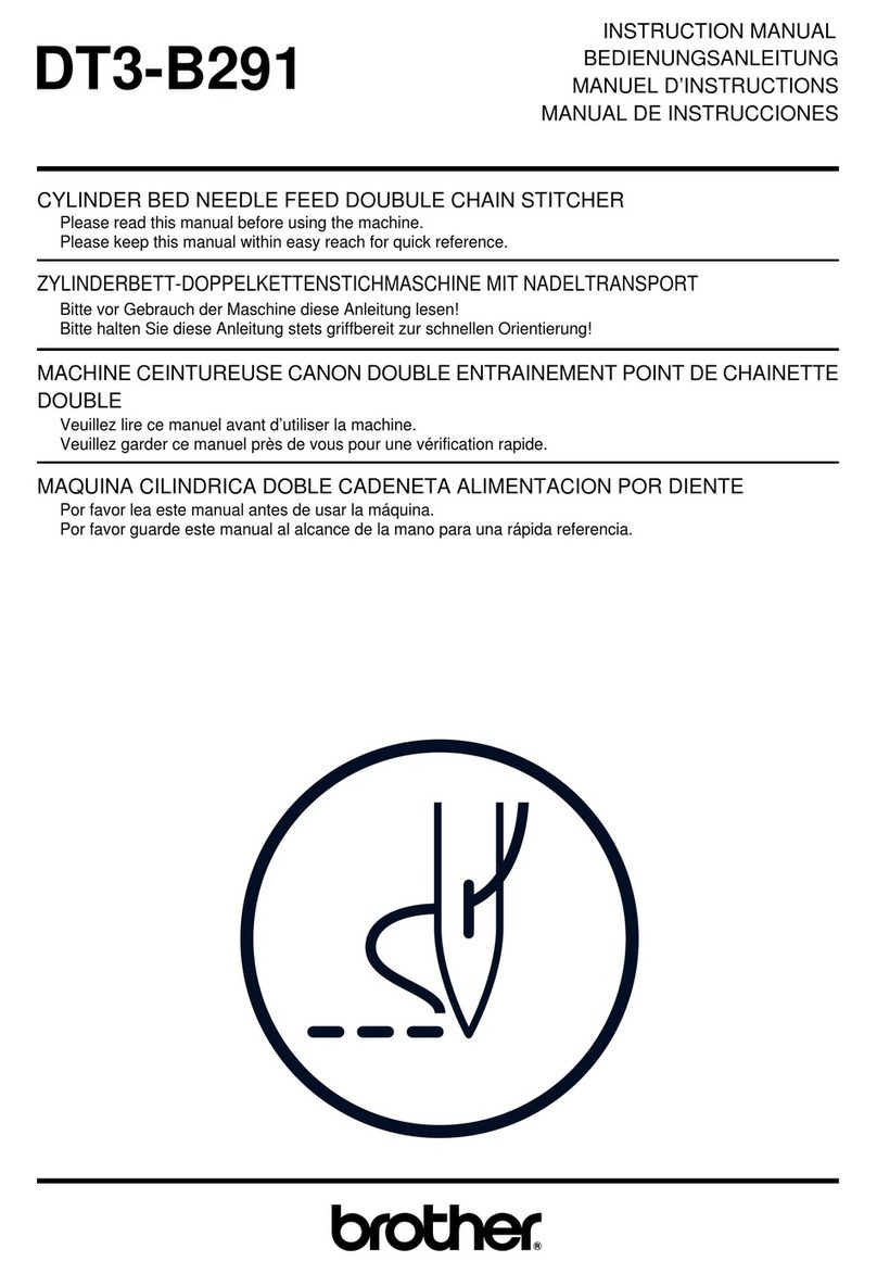
INSTRUCTION MANUAL
BEDIENUNGSANLEITUNG
MANUEL D'INSTRUCTIONS
MANUAL DE INSTRUCCIONES
...
~
/
082-8791
D
--·----~
~~
.
~--~
~
·~~
I
SINGLE NEEDLE NEEDLE FEED LOCKSTITCH MACHINE
EINNADEL-STEPPSICH-MASCHINE
MIT
NADELTRANSPORT
I
MACHINE A UNE AIGUILLE A ENTRAINEMENT PAR AIGUILLE ET POINT D'ARRET
MAQUINA DE COSTURA RECTA DOBLE ARRASTRE
AGUJA
Y DIENTES
BROTHER
INDUSTRIES, LTO.
NAGOYA,
JAPAN
From the library of: Superior Sewing Machine & Supply LLC
Ill
Thank
you
very much
for
your
purchase
of
a BROTHER sewing machine.
The
full performance
of
y
our
new
sewing machine
depends
, above all, on
cor
rect
operatio
n.
Be sure
to
carefully read
the
f
ol
low
ing
instr
uct
i
ons
before u
se.
Ill
Vielen Dank, daB Sie sich fUr eine BR
OTHER-Niihmaschine
entsc
hie
de
n haben.
Die Leistungsfiih
igke
it
lh
rer neuen
Nii
hmaschine
hii
n
gt
vor
allem von
der
ric
htigen
Bedi
enu
ng ab.
Lesen Sie
daher
bitte
vor
Gebrauch
di
ese Bedienungsa
nl
eitung
sorgfiiltig
durch.
Ill
Nous vous remercions d'
avoir
achete une
machine
a
coudre
BROTHER.
Les performances
de
votre nouvelle machine a
coudre
dependent
, avant tout, de son utilisation
corre
cte.
Lisez attentivement les i
nstru
ctio
ns suivantes avant
ut
ilisation.
Ill
Muchas
gracias
por
haber
adq
u
irido
una maq
ui
na
de
coser
BROTHER.
El buen rendimien
to
de
su nueva maquina de
coser
de
pende sobre
todo
de
su
correcto
funcionamie
n
to
.
No
deje
de
leer cuidadosamente las
instrucciones
siguientes antes de
comenzar
a
usar
la.
Specifications
/
Technische
Daten
/Sp
ec
ification
s/E
sp
e
clficacion
es
8---i
I""
0 Needle
bar
Nadelstange
Barre
aiguille
Barra
de
aguja
0
I
T '
8 Pres
se
r-regulation
thumb
screw
StoffdruckerfuB-Regulierschraube
Vis aoreille
du
regulateur
de
pressi
on
Torn
il
lo
de
mariposa para
regulaci6n
del prensatelas
9 Thread retainer
FadendurchfUhrung
Retenue
de
fil
Retenedor del
hilo
@
BROTHER
INDUSTRIES
,
LTD.
082-8791-
~·~~
~
1-
MADE
IN
JAPAN
1--
J I
DB2-
B791
-5
Use For medium For thick
materials materials
Sewing speed
5000
spm
35
00 spm
Maximum stitch length 4
mm
5
mm
Pre
ssure by Stopper 6
mm
foot
height
by
Knee lifter
10
mm
or more
Feed
dog height 0.8
mm
Needles DB X 1
#1
1
-#
18
0 Pre-ten
sio
n
Vorspannung
Pretension
Tension
prelim
inar
0 Pulley
Riemenscheibe
Poulie
Po
lea
0 Feed-reverse lever
Umk
ehrhebel
1.2
mm
#19
-
#22
Levier d'inversion d'
entralnement
Palanca
de
retroceso
de
Ia
alimentaci6n
* With
automat
ic
thread
trimme
r machines
for
medium
thick materials, use a sewing speed of 4500 spm.
* Bei
Ma
schinen
mit
automatischem Fadenabschneider muB fUr
mitteldicke
Stoffe
eine
Niihg
eschw
indigkeit
von
4500
Stichen
pro
Minute
gewiihlt
werden.
*
Pour
les machines avec
coupure
de
fil
automatique
et avec
un
travail a
courdre
d'epaisseur
moyenne
,
utiliser
Ia vitesse
de
couture
de
4500
pts
/min.
*
En
las maquinas de
coser
con
cortahilos
automaticos, para tejidos
de
prosor
medio,utilizaru
na
ve
loc
idad
de
4.500 ppm.
-
1-
From the library of: Superior Sewing Machine & Supply LLC
Setting the cushions at the
four
corners
* Set the oil pan 0 as above.
* Put the hinges8 intothe holes of the bed and adjust them to the rubberhinge0 then place the machine
onto
thehead
cushion 0
for
head
at
four
corners.
Aufstellung der Niihmaschlne
* Die Olwanne 0 wie in der oberen Abbildung gezeigt ahbringen.
* Die Scharniere
f)
in die Tischaussparung einpassen, auf
die
Gummiauflagen0 ausricten unddas Maschinenoberteil
auf
die
an allen vier Ecken vorhandenen
Dumpier
0 stellen.
Mise
en
place des tampons aux quatre
coins
* Mettre le reservoir d'huile 0 comme ci
-de
ssus.
* Mettre lescharnieres
f)
dans lestrousdu socle et les regleravec
Ia
base
caoutchouc
articulee
o.
Place
Ia
machine
sur
les quatre amortisseurs 0 de
Ia
tete
aux
quatre coins.
Colocacl6n
de almohadlllas en las
cuatro
esqulnas
* Coloque Ia charola del aceite 0
como
se indica arriba.
* Ponga las bisagras
f)
en losagujeros de
Ia
cama y ajuste estas a
Ia
base de hule
de
las bisagras0 entonces
coloque
Ia
cabeza de
Ia
maquina
en
las almohadillas de hule 0 que hay en l
as
cuatro esquinas de Ia charola del aceite.
about 1
mm
Adjustment of the knee
lifter
stoppers
1.
Adjust the screw0 so that there will be a clearance
of
about
2 mm between the knee
lifter
0 and knee
lifter
complying
bar
f)
and then fasten
it
securely with the nut.
2.
Adjust the screw0 so that there will be a clearance
of
about
1
mm
between the knee
lifterO
and the oil pan when the
knee
lifter
plate is pushed.
Elnstellen
der
Andruckvorrlchtung-Abstandsbolzen
1.
Den IInken Abstandsbolzen 0 so einstellen, daB der Abstand zwischen der Andruckvorrichtung 0 und der
Schiebestange
f)
ungefiihr
2 mm betriigt; dann den Bolzen mit der
Mutter
festsc
hr
auben.
2.
Den rechten Abstandsbolzen 0 so einstellen, daB der Abstand zwischen
der
Andruckvorrichtung0 und
der
Olwanne
ungefiihr
1 mm betriigt, wenn
die
Andruckplatte
hochgedruckt
ist.
Reglage des butees
du
poussolr coude
1. Regier
Ia
buteeguache0 de sorte
qu
'il ya
it
unjeud'environ2mm entrele
poussoircoudeO
et
Ia
tige
poussoirG.
Puis,
bien serrer
Ia
dite butee au moyen de l'ecrou.
2.
Regier
Ia
butee
droiteO
de sorte qu'il
yait
unjeu d'environ 1mm entrele
poussoircoudeO
et
lecarterd'huile
lor
sque
Ia
plaque de poussoir
co
ude est poussee.
Ajuste de
los
retenes del
alzador
de rodllla
1.
Regular el reten de izquierda0 de suerte que haya un espacio libre de unos 2 mm. entreel alzador de rodilia0 y Ia
varilla de empuje
f)
apretandolo, luego, bien
con
el tornillo. ·
2. Regular el
formllo
0 de sue
rt
e tal que haya un espacio
libre
aproximado de 1 mm. entreel alzador de rodilia0 y
Ia
charola de aceite cuando
Ia
placa del alzador de rodilla este empujada.
-2
-
From the library of: Superior Sewing Machine & Supply LLC
\_
Lubrication
1.
Slowlypouroil into the oil pan to the HIGH mark. Ifthe
oil level falls below the LOW mark, add oil.
2. If the oil becomes contaminated, remove the oil cover
screw
0.
3. Wipe away contamination from the magnet
8.
and the
oil pan.
3aE
Use
the oil specified by BROTHER: Hi-White 70.
Schmlerung
1. Langsam
OJ
bis zur linken Markierung (,HIGH") einfUIIen.
Wenn
der Olstand unter die rechte Markierung (
..
LOW")
abfallt,
01
nachfUIIen.
2.
Wenn das
01
verschmutzt ist, die OlablaBschraube 0 entfernen.
3.
Den
Schmutz vom Magneten
Gundder
Olwanne entfarnen.
3aE
Cas
von BROTHER empfohlene WeiBol 70 verwenden.
Lubrlflcatlon
1.
Verser l'huile lentement jusqu'an repere "HIGH" situe agauche.
Si
le
niveau d'huile tombe en dessous du repere "LOW" situe adroite, ajouter
de
l'huile.
2.
Si
l'huile deviant sale, retirer
Ia
vis du carter d'huile
o.
3.
Retlrer led dechets de l'aimant
8.
3aE
Utlliser l'huile recommandee par BROTHER: Hi-white 70.
Lubrlcaclon
1. Echar aceite lentamente hasta alcanzar
Ia
marca ("HIGH") de
Ia
izquierda.
Sl
el
nivel del aceite baja
mas
alia de
Ia
marca ("LOW))
de
Ia
derecha, agregar aceite.
2.
Si
el
aceite
se
pone sucio, quitar
el
tornillo de
Ia
cubierta de aceite
o.
3.
Limpiar
Ia
suciedad
en
los imanes
8,
yen
Ia
charola de aciete.
3aE
Usar
el
aceite expecificado BROTHER: Hi-White 70.
Rotating direction of machine
How
to
Install the belt
* The correct operating direction of the machine is counter-
clockwise
as
viewed from the pulley side.
* Press belt 0 with your thumb, and adjust the belt tension by
turning
nut
8
so
that the belt 0 can
be
depressed
15"'
20
mm
with a finger
Gurtmontage
*
Von
der Riemenscheibe aus betrachtet
muB
die Maschinegegen
den Uhrzeigersinn Iauten.
*
Den
Gurt 0 mit dem Daumen drucken. Mit der Mutter 8 die
Gurtspannung so einstellen,
daB
der Gurt 0
15
bis
20
mm
nachgibt.
Installation de
Ia
courrole
*
Le
sens exact de
Ia
marche de
Ia
machineest
en
sens inversedes
aiguilles d'une montre,
vu
du
cOte
de
Ia
poulie.
* Appuyersur
Ia
courroie0 avec le pouceetajuster
Ia
tension de
Ia
courroie
en
tournant l'ecrou8 de sorte que
Ia
fleche soitde
15
"'
20mm.
Manera de colocar Ia correa
*
El
sentido de funcionamiento correcto de
Ia
maquina
es
hacia
Ia
izquierda
si
se
mira desde
el
lado de
Ia
polea.
* Habra que apretar
Ia
correaO
con
el
pulgary
regular
Ia
tensi6nde
Ia
misma haciendo girar
Ia
tuerca8 de manera tal que
Ia
correa
ceda hacia adentro de unos
15
a
20
mm.
-3-
From the library of: Superior Sewing Machine & Supply LLC
Precautions
be
f
ore
installing
the
belt
cov
er:
1.
Fi
t the V belt
onto
the sewing machine pulle
y.
2.
Bring the sewing machine
down
toward the horizontal position, and then install the belt cover.
3. The set screws
for
belt cover instalation are in the accessories pocket.
Vorkehrungen
vor
dem
Anbrlngen
des
Rlemenschutzes
1. Den
Ke
ilriemen an
der
Motorriemenscheibe anbringen.
2. Die N
iih
ma
sc
hine in die Horizontalstellung umklappen und den Riemenschutz montieren.
3. Die Schrauben
fur
den Riemenschutz befinden sich in der Zubehortasche.
Precautions
a
prendre
avant
de
monter
le
couvercle
de
courrole:
1. Monter Ia courroie trapezo'idale
sur
Ia
poulie de Ia machine.
2.
De
scen
dr
e Ia machine vers
Ia
position horizontals, puis
monter
le couvercle de
courro
i
e.
3.
Les vis de montage
pour
Ia
pose du couvercle
de
courroie se trouvent dans
Ia
poche
tt
e des accessoires.
Precauclones
a
tomar
antes
de
instalar
Ia
cublerta
de
Ia
corr
ea:
1. Colocar
Ia
correa trapozoidal en Ia polea de
Ia
maquina de coser.
2.
Bajar
Ia
maquina a su posicion horizontal normal, e instalar Ia cubierta de
Ia
correa.
3. Los
tornillos
de fijaci6n para Ia instalaci6n de
Ia
cubierta de Ia
cor
rea
se
encuentran en Ia bolsa de accesorios.
1. Screw the white stud 0 into the machine head.
2. Temporarily tighten screw A
f)
and the spring was
her
0 to the white stud.
3.
Install belt cover U 0 with screw A 8
as
shown in the figure at the abave.
4.
Install belt cover U 0 with screw B 0 and the spring washer 0 .
* When installing belt cover U
0.
plea
se
bring
down
the machine.
5.
In
stall belt cover D 8 with screws 0 and washers
f).
* When installing belt cover D
f),
plea
se
set up the machine.
*When replacing the belt, remove belt cover U 0 .
1. Die weiBe Stiftsc
hr
aube 0 an
der
Maschinenseite einschrauben.
2. Die Schraube A
f)
und den Federring 0 provisorisch an
der
wei
Ben
Stiftschraube 0 festziehen.
3.
Den Riemenschutz U 0
mit
der
Schraube A 8 befestigen (siehe obenstehende Abbildung).
4.
Den Riemenschutz U 0
mit
der Schraube B 0 und dem Federring e befestigen.
* Den
Ri
emensc
hutz
U 0 in
der
heruntergeklappten stellung
der
Maschine anbringen.
5.
Den Riemenschutz D
f)
mit
den
beiden Schrauben 0 und Unterlegscheiben 0 befestigen.
* Zum Anbringen des Riemensc
hu
tzes D
f)
die
Maschine aufstel
le
n.
* Zum Austausch des Riemens den Riemenschutz U 0 entfernen.
1. Visser le
gOUJ')n
blanc
0 dans Ia tete de Ia machine.
2. Visser tempor;;irement
Ia
vis A
f)
et
Ia
rondelle de ressort 0 sur le goujon blanc 0 .
3.
Installer le couvercle de
courroie
U 0 avec
Ia
vis A
f)
comme montre dans Ia figure superieure.
4.
Installer le couvercle de
courroie
U 0 avec
Ia
vis B 0 et Ia rondelle
de
ressort e.
* Quand on installe le couvercle
de
courroie U
0.
descendre
Ia
machine.
5.
Install
er
le couvercle de
cou
rroie D 0 avec vis 0 et
ronde
lles
f)
.
* Quand
on
installe le couvercle de
courro
ie D
f),
dresser Ia machine.
* Quand on remplace Ia
courro
i
e,
retirer le couvercle de courroie U 0 .
1.
Atornillar
el esparrago blanco 0 en Ia cabeza de
Ia
maquina.
2.
Apretar provisionalmente el t
orn
illo A
f)
y Ia arandela de resorte 0 en el esparrago blanco 0 .
3.
lnstalar Ia tapa U 0 de
Ia
correa
con
el
tornillo
A 0 tal
co
mo
se muestra
en
Ia figura de Ia arriba.
4. lnstalar Ia tapa U 0 de Ia correa
con
el
tornillo
B 8 y Ia arande
Ia
de resorte e.
* AI instalar
Ia
tapa U de Ia
co
rrea
0.
poner Ia maquina de costado.
5. lnstalar Ia tapa D de Ia correa
f)
con
sus
tornillos
0 y arande
la
s
C)
.
*
AI
instalar Ia tapa D de
Ia
correa
f)
, levantar Ia maquina.
*A
I cambiar
Ia
correa,
quitar
Ia tapa U de
Ia
co
rrea 0 .
-4-
From the library of: Superior Sewing Machine & Supply LLC
0
Removal of the bobbin case
1.
Raise
the needle above the needle plate.
For Standard
For
Thread
Trimmer
2.
Pull the latch of bobbin case 0 out and remove the bobbin case from the rotary hook.
3.
The bobbin 8 will come out when the latch is released.
4.
Bobbin case 0 Installation is the reverse of removal order.
~
Be
sure to place the bobbin case seat8 inside thebobbincase. Alsoabobbinspring8 is included on automaticthread
trimming machines.
Herausnehmen der Spulenkapsel
1.
Die Nadel hochstellen, so
daB
sie uber der stichplatte steht.
2.
Die Sperrlasche der Spulenkapsel 0 herausklapen. Dann die Spulenkapsel vom Greifer nehmen.
3.
Die Spule 8 fallt heraus, wenn die Sperrlasche losgelassen wird.
4.
Das
Elnsetzen der Spulenkapsel 0 erfolgt in umgekehrter Reihenfolge des Herausnehmens.
3SE
Der Spulenkapselsitz 8
muB
in die Spulenkapsel eingesetzt warden. Bel Maschinen mit automatischem
Fadenabschnelder ist eine Spulenfeder 8 vorhanden.
~
D6pose de Ia caneHe
1.
Elever l'algullle au-dessus de
Ia
plaque aaiguille. .
2.
Lever le clip du boitier de Ia canette
o.
Sortir le boitier de
Ia
canette du crochet rotatif.
3.
La
canette 0 sortira lorsque le clip est relache.
4.
Pour
Ia
mise en place du boitler de
Ia
canette
0.
proceder com
me
pour le retrait du boitierde Ia canette, mais dans
l'ordre inverse.
*Veilleraplacerlesiegedu boitierdecanette8 al'interieurduboitierde
Ia
canette. Unressortdecanette8 est inclus
sur.
les machines avec coupure de fll automatique.
Manera de sacar
Ia
caja de Ia boblna
1.
Levantar
Ia
aguja sobre
Ia
placa
de
aguja.
2.
Tirar para arriba
el
cerrojo de
Ia
caja de
Ia
bobina 0 y sacar
Ia
caja de
Ia
bobina del cangrejo.
3.
La
bobina 8 saldra
al
soltar el pesflllo.
4.
El
orden de instalaci6n de
Ia
caja de
Ia
bobina 0
es
el inverso al de desmontaje.
~ Verificarque
se
haya colocadoel asientode
Ia
cajade
Ia
boblna8 dentro
de
Ia
cajade
Ia
bobina.Tambien
se
ha incluido
un
resorte de bobina 8
en
las
maquinas de coser con cortahflos automatico. •
Threading the bobbin case
1.
Insert the bobbin into the bobbin case.
2.
Pass
the thread through the slot 0 and under the lower thread adjustment spring
8.
3.
Pull the thread through delivery
eye
8 at one end of the lower thread adjustment spring
8.
4.
Holding the bobbin case latch, insert the bobbin case Into the rotary hook.
FadenfQhrung In der Spulenkapsel
1.
Die Spule
In
die Spulenkapsel stecken.
2.
Den
Faden
durch den Schlitz 0 und unter die Unterfaden-Einstellfeder0 fuhren.
3.
Den
Faden
durch das Zufuhrloch 8
am
Ende der Unterfaden-Einstellfeder 8 zlehen.
4.
Ole
Sperrlasche halten und die Spulenkapsel in den Greifer einsetzen.
Enfllage
du
bottler de
Ia
canette
1.
Mettre
Ia
canette dans le boitier de
Ia
canette.
2.
Passer
le
til dans
Ia
fente 0 et so
us
le ressort
de
reglage du fil inferieur
0.
3.
Tirer le fll par le chas de passage 8 al'une des extremites du ressort de reglage du fil inferieur
8.
4.
Tenir le boitler de
Ia
canette par le
clip
et introduire le boitier dans le crochet rotatif.
Enhebrado de Ia caja de Ia boblna
1.
Meter
Ia
bobina
en
Ia
caja de
Ia
bobina.
2.
Pasar el hilo
por
Ia
ranura 0 y
por
debajo del resorte de ajuste del hilo inferior
0.
3.
Tirar
el
hilo a traves del ojo de entrega 8
en
una de las puntas del resorte de ajuste del hilo inferior
o.
4.
Sostener el pestillo de
Ia
caja de
Ia
bobina e introducir
Ia
caja de
Ia
bobina
en
el
cangrejo.
-5-
From the library of: Superior Sewing Machine & Supply LLC
~\
•
Gufwlckeln des unterfadens
1.
Die Spule 0 auf die Spulerspindel 8 stecken.
2.
Den
Spulerhebel 8 ganz nach oben drucken.
Lower thread winding
1.
Fit the bobbin 0 onto the bobbin winder spindle
8.
2.
Push the bobbin winderstop latch8 completely upward.
3.
Afterwinding the thread around the bobbin0 afewtimes
In the direction of the arrow, operate the machien.
4.
If
the thread cannot
be
wound evenly, adjust the bobbin
winder tension bracket e by moving
it
to the left
or
right
after loosening the set screw
8.
~To
wind more thread on the bobbin
0.
tighten the
adjustment screw
o.
3.
Den
Faden elnlnge Male
In
Pfeilrichtung
urn
die Spul 0 wlckeln und die Nahmaschine betatigen.
4.
Wenn der
Faden
nlchtgleichmaBigaufgewickeltwerden kann, dieStellschraube8 losen und den Spulerspannhaltere
nach links oder rechts verschieben.
~
Urn
mehr Faden auf die Spule 0 zu wickeln, die Schraube
ct
anziehen.
Boblnage du fll lnferleur
1.
Placer
Ia
canette 0 sur
Ia
broche du bobineur
e.
2.
Pousser le loquat d'arr6t du bobineur 8 completement vers le haut.
3.
Faire fonctionner
Ia
machine apres avoir enroule
le
til plusieur fois autour
de
Ia
canette 0 dans le sens de
Ia
fleche.
4.
Si
le til ne peut pas 6tre
~nroule
de
fa~on
reguliere, regler le supportdetension du
bobineure
en
le
depla~ant
vers
Ia
gauche ou
Ia
droite apres avoir desserre
Ia
vis d'arr6t
8.
~.
Pour enrouler plus de til sur
Ia
canette
0,
serrer
Ia
vis de reglage
8.
Boblnado de hllo Inferior
1.
Colocar Ia canilia 0 en
el
huso de Ia canillera
8.
2.
Tirar de
Ia
traba de tope de
Ia
canillera 8 completamente hacia arriba.
3.
Luego de enrollarel hiloalrededorde
Ia
canilia0 varias vueltasen el sentidoindicado
porIa
flecha, hacerfuncionar
Ia
maquina.
4.
Si
el hilo no queda bobinado de forma pareja, ajustar
Ia
mensula 8 para
Ia
tension de
Ia
canillera moviendo
Ia
mlsma
hacia
Ia
derecha y hacia
Ia
izquierda luego de aflojar
el
tornillo de fijaci6n
8.
~ Para boblnar
mas
hilo
en
Ia
canilla
0.
apretar
el
tornillo de ajuste
ct.
Long groove
Attachment
of
the needle
Insert the needle 0 completely, making sure that the long groove of
the needle is on the left, and tighten it with the screw
8.
~ Use a DB X 1 machine needle.
Befestlgung der Nadel
Die
Nadel 0 ganz hineinschieben, wobei sich die Nadelrille links
befinden
muB.
Dann die Nadel mit der Klemmschraube 8
befestigen.
~
Eine Nadel
DB
X 1 verwenden.
Mise
en
place de l'algullle
lntroduire l'aiguille 0 afond. S'assurer que
sa
gorge
se
trouve a
gauche, puis serrer al'aide de
Ia
vis de serrage de l'aiguille
8.
~
Utiliser une aiguille de machine
DB
X
1.
Manera de colocar Ia aguja
Meter bien
Ia
aguja 0 asgurandose de que
Ia
ranura larga de
Ia
misma quede hacia
Ia
izquierda apretando luego
Ia
misma con
el
tornillo
e.
~
Usar una aguja para maquina
de
coser
DB
X
1.
Upper threadlng/Einfiideln des Oberfadens/Enfllage superleur/Enhebrado superior
-6-
From the library of: Superior Sewing Machine & Supply LLC
0
Thread tension
Stitches when upper thread
tension
is
too loose
-
Stitches when upper thread
tension
is
too tight
-
Id
eal
seam
* Adjust the l
ower
thread tension by using the
lower
thread tensionadjustmentscrew0
so
thatthe bobbin case
will
slip
down
of
its
own
weight when
it
is suspended from the lower thread
with
the end
of
the thread held by hand.
* L
ower
the presser foot and adjust the
upper
thread tension by using the
nut
f)
.
Fadenspannung
* Mittels der Unterfaden-Einstellschraube0 die Spannung des Unterfadens so einstellen,
daB
die
Spulenkapsel durch
ihr
Eigengewicht nach unten rutscht, wenn sie vom Faden gleitet.
* Den NahfuB aufsetzen und mittels
der
Oberfaden-Einstellschraube 0 die Spannung des Oberfadens einstellen.
Tension de
fll
* Regi
er
Ia tension
du
til
inf
er
ieurau moyen
de
Ia vis
de
reglage de Ia tension
du
fil inferieurO desorteque le
boitierde
Ia
canette glisse de son
pr
o
pr
e poids lorsqu'il est suspendu par le til inferi
eu
r,
l'extremite de celui-ci etant tenu dans Ia
main.
* Baisser le pied de biche et r
eg
ler Iatensiondu filsuperi
eur
au moyen deIavis dereglagede
Ia
tensiondufil
superieurO.
Tensl6n del hllo
* RegularIa tension del
hila
inferior
usandoel
tornillo
correspondientede ajustedetensiondel
hila
inf
eriorO
de manera
tal
que
Ia
caja de
Ia
bobinase caiga
por
su pesoal suspenderla del
hilo
inferior
sujetando
Ia
puntadel
hila
con
Ia mano.
* Bajarel prensatelas y regular
Ia
tension del
hilo
superior
usando Ia tuercocorrespondiente deajuste
de
Ia
tension
del
hilo s
up
er
ior
f)
.
Fadenabnahmefeder
Tension spring
* The standard operation range of the tension
spring is about 7
~
10 mm. The standard
tension at this time is about
25
~
30 g.
*
To
adjust the operation range of the tension
spring, loosen t
he
screw
0,
and
turn
the upper
thread-tension assembl
y.
* To adjust the tension
of
the tension spring,
fit
a
sc
rewdriver into the slot, and turn the tension
stud 0
as
appropriate.
* Der Abstand
der
Fadenabnahmefeder betragt normalerweise 7
~
10 mm. Dabei ist
die
Spannung ungefahr 25
~
30
g.
* Um den Abstand
der
Abnahmefeder einzustellen, die Schraube 0 losen und
die
obere Faderspannungsvorrichtung
drehen.
*
Um
die Spannung der Abnahmefeder einzustellen, einen Schraubenzieher in den Schlitz sleeken
und
die
Spannungsschraube
f)
in
die
entsprechende R
ichtu
ng drehen.
Ressort du levier du
fll
*
La
plage de fonctionnement standard
du
ressort du levier
du
fil est de 7 a
10
mm environ. La tension standard ace
moment est de
25
a
30
g env
ir
on
.
* Dans lebutde regl
er
Ia
piage de fonctionnementderessortdu l
evierd
u fil, desserrer IavisO et
tourner
lebl
oc
superieur
de Ia tension du fil.
* Dans le but de regler
Ia
tension
du
ressort
du
levier
du
fil,
introduire
un tournevisdans Ia fente et
tourner
le
goujon
de
tension
f)
selon
Ia
necessite.
Resorte de toma del hllo
* El foncionamiento ordinaria
que
abarca
el
resorte detomadel hila
es
deunos7a
10
mm.
La
tension ordinariaen tal caso
es
de unos
25
a 30 gramos.
* Cuando
se
quiera regular el radio abarcado
por
el
resorte
de
tomadel hilo, habra
que
aflojarel
tornillo
0 y hacer
girar
todo el
conjunto
de Ia tension del
hilo
superior.
* Para regular Ia tension del resorte detoma del hilo, habra
que
meterun
destornilladoren
Ia
ranura haci
enda
luegogirar
el esparrago tensor
f)
como corresponda.
Adjustment of stitch length
* P
us
h the reverse lever 0 halfway down, t
urn
the dial
f)
until
the
desired
number
is aligned
with
the
pin
8 at the top, and release
the reverse lever o.
*
Th
e largerthenumber
is
,thelongerthestitch becomes.Maximum
stitch length is 4 mm
for
medium th
ick
material
s,
and 5 mm
for
th
ick
materials. Reverse feed is a maximum
of
3 mm.
*
The
reverse sewing device
is
the automatic-resetting type.
The
work
will
be fed backward when
the
reverse lever 0 is
depressed, and forward again when
it
is released.
-7-
From the library of: Superior Sewing Machine & Supply LLC
,..~
'
Elnstellen der StlchUinge
* Den ROcklaufhebel 0 halb nach unten drOcken, das Riidchen 0 so welt drehen, bis die gewOnschte Zahl
Ober
dem
oberen Stiff 8 steht, und dann den ROcklaufhebel 0 zurOckstellen.
*
Mit
zunehmender Zahl vergroBert sich
die
Stichlange. Die maximale Stichlange betriigt 4
mm
tor
mitteldickeStoffe, 5
mm
fOr
dicke Stoffe und 3 mm
fOr
ROckwiirtsstiche.
* Die ROcklaufvorrichtung schaltet sich automatlsch urn.
Solange der ROcklaufhebel 0 niedergedrOckt wird,
liiuft
die Maschine in umgekehrter Aichtung; wenn der Hebel
losgelassen wird,
liiuft
die Maschine wleder nach vorne.
Reglage de
Ia
longueur des points
* Balsser le levier de marche inverse 0 de moitle de
sa
course, tournerle cadran 0 jusqu'a
ce
que le numerodesire est
aligne avec Ia goupille 8 situee sur le dessus, et reiAcher le levier
demarche
inverse
o.
*Plus grand est le nombre, plus grande est
Ia
longueurdu point. Pourdes materiaux d'epaisseurmoyenne, Ia longueur
maximum des points estde4 mm; pourdes materiaux de grosseepaisseur, elle est de 5 mm. L'entrainement reversible
est d'un. maximum de 3 mm.
* Le disposltif de couture en marche inverse est du type a remise
en
marche avant automatique.
La
couture se fera
en
marche inverse lorsque le levier
demarche
inverse0 est appuye. Le levier rei
Ache,
Ia
couture
en
marche avant est automatique.
Ajuste de
Ia
longltud de puntada
* Empujar Ia palanca de alimentaci6n para marcha atras 0 mitad hacia abajo, girar el disco 0 hasta que el numero
buscado quedealineadocon el pasador8 en
Ia
parte dearribayvolverasoltar
Ia
palancadealimentaci6nparamarcha
atras
o.
'*
Cuanto mayorsea el numero, mas larga sera
Ia
puntada. La longitud maximade Ia puntada
es
de 4
mm
paratejidos de
grosor medio y de 5
mm
para tejidos gruesos. Para el retroceso de Ia alimentaci6n,
el
maximo es de 3 mm.
*
El
dlsposltlvo para costura marcha atras es
uno
de
tipo
de reposici6n automatics. 0
sea,
teniendo apretada Ia palanca
de alimentaci6n marcha atras, el trabajo se realizara para atras volviendo a hacerse para adelante al soltar dicha
palanca.
Adjustment of presser foot pressure
* The pressure on materials during sewing must
be
as weak
as
possible butstill enough
to
prevent slippage. Adjust,
if
necessary,
by using the adjustment screw
0.
~ Loosen the adjustment nut before adjusting.
Elnstellung des StoffdrOckerfuBdrucks
* Beim Niihen sollte der Druck auf das Niihgut so gering wie
moglich sein, aber groB genug,
daB
die Stoffenichtverrutschen.
Wenn notig,
mit
der Schraube 0 einstellen.
iE
Vor
der Einstellung die Mutter losen.
Reglage de
Ia
pressl6n du presseur
* La pression appliqueesurletissu pendant
Ia
couture
do
it
~tre
aussi faiblequepossible
tout
en
emp~chant
tout
patinage.
Regier, si necessaire,
en
utilisant
Ia
vis de reglage
0.
*Avant de proceder
au
reglage, desserrer l'ecrou de reglage.
A)uste de Ia presl6n del pie del prensatelas
* La presl6nsobrelostejidosdurante
lacosturadebeser
lomas
floja posibleperosinque
se
produzcandeslizamientosde
los tejidos. Ajustarla si fuera necesario utllizando el tornillo de ajuste
0.
'*
Aflojar
Ia
tuerca de ajuste antes de realizar este ajuste.
•
•
Hauteur du presseur
Presser
foot height
Presser foot height
* The standard height
of
the presser
foot
0 is 6 mm when the
presser foot is raised with the presser bar lifter lever 0 .
* Loosen the nut 8
of
the adjustment screw and then the presser
footadjustmentscrew8 so that no pressurewill be applied
to
the
presser foot.
Loosen the set screw
8,
and adjust the presser foot height by
raising
or
lowering the presser bar G.
Stoffdr0ckerfu8h6he
* Wenn
der
StoffdrOckerfuB 0
mit
dem StoffdrOckerfuBhebel 0
hochgestellt wird, betriigt die Standardhohe 6 mm.
* Die Mutter 8 und die StoffdrOckerfuB-Regulierschraube 8
losen,
so
daB
kein Druck aufden StoffdrOckerfuB ausgeObt wird.
Die Stellschraube 8 losen und die Hohe des StoffdrOckerfuBes
durch Verschleben der StoffdrOckerstange G nach oben oder
unten einstellen.
* La hauteurstandard
du
presseurO
estde6
mm lorsquelepresseurestleveavecle levierdureleve-barredepresseurO.
* Desserre l'ecrou 8
de
Ia vis
de
reglage, puis Iavis dereglagedu
presseurG
de
fa«;on
quelepresseurnesubisseaucune
pression.
Desserrer
Ia
vis
d'arr~t
8,
et regler
Ia
hauteur du presseur en elevant ou abaissant
Ia
barre de presseur
ct.
Altura del prensatelas
* La altura estandardel prensatelas0
es
de6mm cuandose levantael presatelascon IapalancaparalevantarIa barradel
prensatelas
0.
* Aflojar
Ia
tuerca8 deltornillodeajustey el tornillodeajustedel piedel prensatelasG paraque nohayapresion sobre
el
pie del prensatelas.
Aflojar el tornillo 8 y ajustar Ia altura del pie del prensatelas haciendo subir y bajar
Ia
barra del prensatelas
e.
-8-
From the library of: Superior Sewing Machine & Supply LLC
S~tandards~e
-~:)~
....
A 8
@h
-~-
Feed
dog
height
··~·......,.;)-·
J-
f
Rises
in
the
a forward direction
~
-~-
r-
f
Descends
in
the
forward direction
Feed dog height
1.
When
the feed dog 0 is raised above the needle plate, standard feed dog heights
are:
0.8 mm, for medium thick
materials, and
1.2
mm
for thick materials.
2.
Adjust the feed dog heightby looseningthescrewG when thefeed
dogO
isatitshlghestposltionfromtheneedle plate
surface, and move the feed lifting arm 8 up and down.
Feed
dog angle
1.
The standard angle ofthe feed dog0 (horizontal totheneedleplatesurfacewhen thefeed dog
Is
atitshighestposition)
is obtained by matching the
"0"
mark
of
the feed plate shaft 8 with the notch on the feed bar arm
8.
•.
In order
to
prevent puckering, raise the feed dog 0 in the forward direction.
• In order
to
prevent the material from slipping, slant the feed dog 0 in the forward direction.
2.
In orderto adjustthe feed dogangle, loosen the screws8 and then turnthefeed plate8
goo
in thedirectionsindicated .fltu.
by the arrows. r ·
~
When the feed dog angle has
been
adjusted, check to confirm that its height has not changed.
Transporteurhtihe
1.
Die Standardhohe
des
Transporteurs0 betragt0,8
mm
fur mltteldlcke Stoffeund
1,2
mm
fUrdlckeStoffe, wenn eruber
die Nadelplatte hochgestellt wird.
2.
Der Transporteur 0 in der Hochstellung von der Nadelplatte durch Losen der Schraube 8 einstellen und den
Hochstellhebel 8 nach oben und unten bewegen.
Transporteurwlnkel
1.
DerStandardwinkel des Transporteurs0 (horizontal zurNadelplate, wenn derTransporteurin derHochstellungsteht)
wird durch Ausrichten der "0"-Marke
der
Transporteurplattenwelle 8 mit der Kerbe der Transporteurstange 8
erhalten.
• Urn ein Zusammenschieben des Materials
zu
verhindern,
muB
der Transporteur 0 nach vorne angehoben warden.
• Urn ein Rutschen des Materials
zu
verhindern,
muB
der Transporteur 0 nach vorne geneigt werden.
2.
DerTransporteurwinkel kann eingestelltwerden, wenn die Schraube8 gelost und dieTransporteurplatte8
urn
goo
In
der Pfeilrichtung gedreht wird.
3SE
Nach dem Einstellen des Transporteurwinkels
muB
die Transporteurhohe kontrolliert warden.
Hauteur
de
Ia
griffe d'entrainement
1.
Lorsque
Ia
griffed'entrainement0 est eleveeau-dessus de
Ia
plaqueaaiguille,leshauteursstandard de
Ia
griffesontde
0,8
mm
pour des materiaux d'epaisseur moyenne et de
1,2
mm
pour des materiaux
de
grosse epaisseur.
2.
Regier
Ia
hauteurde
Ia
griffed'entrainement
en
desserrant
Ia
visG
lorsque
Ia
griffed'entrainementest
en
position haute
par rapport
Ia
plaque aaiguille, et deplacer le bras elevateur 8 vers le haut ou vers
le
bas.
Angle de
Ia
griffe d'entrainement
~
1.
L'angle normal
de
ra
griffe d'entrainement 0 (parallele a
Ia
surface
de
Ia
plaque a aiguille lorsque
Ia
griffe
d'entrainement est
en
position haute) est obtenu
en
faisant correspondre le repere
"0"
de
l'axe de
Ia
plaque
d'entrainement 8 avec l'encoche du bras
de
Ia
barre d'entrainement
8.
• Pour eviter le tassement, elever
Ia
griffe d'entrainement 0 vers l'avant.
• Pour eviter le glissement du tissu, incliner
Ia
griffe d'entrainement 0 vers l'avant.
2.
Pour regler l'angle de
Ia
griffe d'entrainement, desserrer
Ia
vis 8 puis tourner
Ia
plaqued'entrainement8 de
goo
dans
les directions indiquees par les fleches.
~
Lorsque l'angle de
Ia
griffe d'entrainement a ate, verifier si
Ia
hauteur n'a pas ete modifiee.
Altura del allmentador
1.
Cuando
el
alimantador 0
se
levanta
por
encimade
Ia
place de aguja, las alturas estandar del alimantadorson: 0,8
mm
para tejodos de grosor medio y
1,2
mm
para tejidos gruesos.
2.
Ajustar
Ia
altura del alimantadoraflojando el
tornilloG
cuando
el
alimentadorO esta
en
su
posici6n
mas
altadesde
Ia
superficie de
Ia
placa de
Ia
aguja, y mover arriba y abajo
el
brazo levantador del alimentador
e.
Angulo del allmentador
1.
El
angulo estandardel alimentadorO (horizontal a
Ia
superficiede
Ia
placede
Ia
agujacuando
el
alimentadoresta
en
su
posici6n
mas
alta)
se
obtiene haciendo coincidir
Ia
marca
"0"
del eje de
Ia
placa
de
alimentaci6n8 con
Ia
muesca
en
el
brazo
de
Ia
barra
de
alimentaci6n
e.
• A fin de evitar acumulaci6n de tejldo, levantar
el
alimantador 0 hacia adelante.
• A fin de evitar que
el
tejido resbale, inclinar
el
alimentador 0 hacia adelante.
2.
Para ajustar
el
angulo del alimentador, aflojar
el
tornillo 8 y luego girar
Ia
placa de alimentaci6n 8
goo
en
las
direcciones indicadas por
las
flechas.
~
Despues de haber ajustado
el
angulo del alimentador, comprobar que
su
altura no ha cambiado.
-9-
From the library of: Superior Sewing Machine & Supply LLC