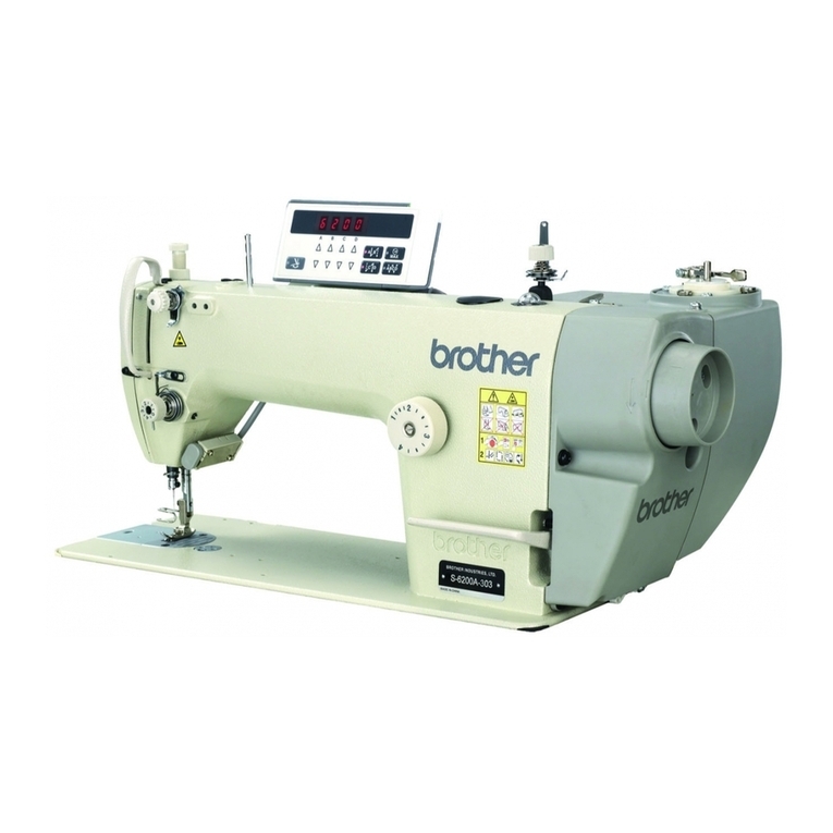
S-7300A
CONTENTS
1. MACHINE SPECIFICATIONS ...............1
2. NOTES ON HANDLING.........................2
3. FUNCTION SETTINGS..........................3
3-1. List of special functions when power is
turned on.......................................................... 3
3-2. Memory switch setting method (Advanced) ....5
3-3. List of memory switch settings ........................6
3-4. Energy saving mode setting method .............21
3-5. Input checking method ..................................23
3-6. Output checking method................................ 25
3-7. Protect setting................................................27
3-8. Error history ................................................... 30
3-9. Maintenance information ...............................32
3-10. Software version checking method .............34
3-11. Software version updating method..............35
3-12. Serial number checking method ..................37
4. MECHANICAL DESCRIPTIONS .........38
4-1. Upper shaft and needle bar mechanism .......38
4-2. Lower shaft and rotary hook mechanism ......39
4-3. Feed mechanism ...........................................40
4-4. Lubrication mechanism..................................41
4-5. Thread trimming mechanism .........................42
4-6. Tension release and presser foot mechanism
(Other than premier specifications) ...............47
4-7. Tension release and presser foot mechanism
(Premier specifications) .................................48
4-8. Thread wiper mechanism ..............................49
5. DISASSEMBLY ...................................50
5-1. Knee lifter assembly ......................................50
5-2. Cable tie ........................................................51
5-3. Connector ......................................................51
5-4. Covers ........................................................... 52
5-4-1. Top cover and pulley cover.................52
5-4-2. Panel ...................................................53
5-5. Tension release wire and thread trimmer
solenoid .........................................................54
5-6. Wick holder and oil tube
(-[]0[] specifications only)...............................56
5-7. Oil tank and bed bottom cover ......................57
5-7-1. Oil tank ................................................57
5-7-2. Bed bottom cover................................ 58
5-8. Stand ............................................................. 58
5-9. Needle and presser foot ................................ 59
5-10. Hand switch and X-over seam sensor.........60
5-10-1. Cord holder and Thread wiper
device assembly ...............................60
5-10-2. Fase plate, X-over seam sensor
and Hand switch assembly .............. 61
5-11. Tension mechanism (Other than
premier specifications)................................ 62
5-12. Tension mechanism (Premier
specifications) ............................................. 63
5-13. Needle plate, feed dog, etc. ........................ 64
5-14. Bobbin case, rotary hook and thread
trimmer mechanism..................................... 65
5-15. Feed mechanism ........................................ 66
5-15-1. Disassembling the feed
mechanism ....................................... 66
5-15-2. Disassembling the feed bar unit....... 67
5-16. Presser foot mechanism ............................. 68
5-17. Knee lifter lever mechanism........................ 69
5-18. Tension pulley............................................. 69
5-19. Needle bar and thread take-up
mechanism.................................................. 70
5-20. Pulley and timing pulley U........................... 71
5-21. Main shaft motor ......................................... 72
5-22. Timing belt................................................... 73
5-23. Lower shaft, lower shaft gear and lower
shaft fan ...................................................... 74
5-24. Plunger, rotary hook shaft, rotary hook
shaft gear and thread trimmer cam............. 75
5-25. Thread wiper ............................................... 76
6. ASSEMBLY .........................................77
6-1. Plunger, rotary hook shaft, rotary hook
shaft gear and thread trimmer cam............... 78
6-2. Lower shaft, lower shaft gear and lower
shaft fan ........................................................ 79
6-3. Upper shaft mechanism ................................ 80
6-4. Timing belt..................................................... 81
6-5. Pulley and main shaft motor ......................... 82
6-6. Tension pulley............................................... 85
6-7. Knee lifter lever mechanism.......................... 85
6-8. Needle bar and thread take-up mechanism.. 86
6-9. Presser foot mechanism ............................... 87
6-10. Feed bar unit mechanism ........................... 88
6-11. Feed mechanism ........................................ 89
6-12. Bobbin case, hook and thread trimmer
mechanism.................................................. 93
6-13. Oil tank and bed bottom cover .................... 94
6-13-1. Bed bottom cover ............................. 94
6-13-2. Oil tank ............................................. 95
6-14. Stand........................................................... 96
6-15. Needle and presser foot.............................. 97
6-16. Hand switch and X-over seam sensor ........ 98
