BRUEL & KJAER 9640 User manual

Technical
Documentation
HEADQUARTERS: DK-2850 Nærum · Denmark · Telephone: +45 4580 0500 · Fax: +45 4580 1405 · www.bksv.com · info@bksv.com
Australia (+61) 2 9889-8888 · Austria (+43) 1 865 74 00 · Brazil (+55)11 5188-8161 · Canada (+1) 514 695-8225
China (+86) 10 680 29906 · Czech Republic (+420) 2 6702 1100 · Finland (+358) 9-521 300 · France (+33) 1 69 90 71 00
Germany (+49) 421 17 87 0 · Hong Kong (+852) 2548 7486 · Hungary (+36) 1 215 83 05 · Ireland (+353) 1 807 4083
Italy (+39) 0257 68061 · Japan (+81) 3 5715 1612 · Korea (+82) 2 3473 0605 · Netherlands (+31)318 55 9290 · Norway (+47) 66 77 11 55
Poland (+48) 22 816 75 56 · Portugal (+351) 21 47 11 4 53 · Singapore (+65) 377 4512 · Slovak Republic (+421) 25 443 0701
Spain (+34) 91 659 0820 · Sweden (+46) 8 449 8600 · Switzerland (+41) 44 880 7035 · Taiwan (+886) 2 2502 7255
United Kingdom (+44) 14 38 739 000 · USA (+1) 800 332 2040
Local representatives and service organisations worldwide
Turntable System Type 9640
English BE 1245 – 13
User Manual
ËBE-1245---ÇÎ
BE1245-13_Cover.fm Page 1 Friday, November 25, 2005 10:30 AM

BE1245–13 November 2005
Turntable System Type 9640
Consisting of:
Controllable Turntable Type 5960
From serial number: 1878678
Turntable Controller Type 5997
From serial number: 1760820
Remote Control WB1254
User Manual
BE124513.book Page i Friday, November 25, 2005 10:21 AM

Trademarks
National Instruments is a trademark of National Instruments Corporation
Copyright ©1993 – 2005, Brüel&Kjær Sound & Vibration Measurement A/S
All rights reserved. No part of this publication may be reproduced or distributed in any form,
or by any means, without prior written consent from Brüel&Kjær Sound & Vibration Meas-
urement A/S, Nærum, Denmark
Safety Considerations
This apparatus has been designed and tested in accordance with IEC61010–1 and
EN61010– 1 Safety Requirements for Electrical Equipment for Measurement, Control
and Laboratory Use. This manual contains information and warnings which must be fol-
lowed to ensure safe operation and to retain the apparatus in safe condition. Special note
should be made of the following:
Safety Symbols
The apparatus will be marked with this symbol when it is important that you refer to the
associated warning statements given in the manual.
Chassis Terminal Protective Earth Terminal Hazardous Voltage
Explosion Hazard
The equipment is not designed to be used in potentially explosive environments. It should not
be operated in the presence of flammable liquids or gases.
Warnings
• Switch off all power to equipment before connecting or disconnecting their digital inter-
face. Failure to do so could damage the equipment.
• Whenever it is likely that the correct function or operating safety of the apparatus has
been impaired, it must be made inoperative and be secured against unintended operation.
• Any adjustment, maintenance and repair of the open apparatus under voltage must be
avoided as far as possible and, if unavoidable, must be carried out only by trained service
personnel.
• Do not dispose of electronic equipment as unsorted municipal waste
• It is your responsibility to contribute to a clean and healthy environment by using
the appropriate local return and collection systems
• Hazardous substances in electronic equipment may have detrimental effects on the
environment and human health
• The symbol shown to the left indicates that separate collection systems must be used
for any discarded equipment marked with that symbol
• Waste electrical and electronic equipment may be returned to your local Brüel& Kjær
representative or to Brüel&Kjær Headquarters for disposal
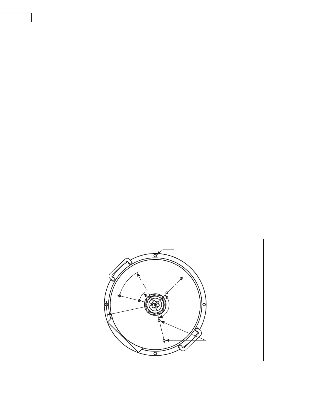
Note: A switch inside Turntable Type 5960 contains mercury. Before destruction of the turnta-
ble, this switch must be removed in order to be recycled or disposed of in a responsible way.
BE124513.book Page ii Friday, November 25, 2005 10:21 AM

Contents
CHAPTER 1
Installation........................................................................................................... 1
Environmental ........................................................................................................................... 1
Power Supply............................................................................................................................ 1
Mounting.................................................................................................................................... 2
CHAPTER 2
Controls and Connectors .................................................................................. 3
Controllable Turntable Type 5960............................................................................................. 3
Front..................................................................................................................................... 3
Rear..................................................................................................................................... 4
Turntable.............................................................................................................................. 4
Turntable Controller Type 5997................................................................................................. 5
Front Panel .......................................................................................................................... 5
Rear Panel........................................................................................................................... 6
Remote Control WB1254.......................................................................................................... 7
CHAPTER 3
Operation............................................................................................................. 9
Manual Use............................................................................................................................... 9
Use of Turntable Controller Type 5997................................................................................ 9
Use of Remote Control WB1245....................................................................................... 10
IEEE Use................................................................................................................................. 11
Installing National Instruments™ IEEE–488.2 Hardware and Software............................ 11
Configuring the IEEE–488.2 for Turntable System Type 9640 ......................................... 11
General.............................................................................................................................. 12
How to Use Turntable System Type 9640 for Measurements ........................................... 13
CHAPTER 4
Service & Repair............................................................................................... 17
CHAPTER 5
The Machinery Directive.................................................................................. 19
Machinery Directive................................................................................................................. 20
Machinenrichtlinie.................................................................................................................... 21
Directive sur la sécurité des machines.................................................................................... 22
CHAPTER 6
Specifications................................................................................................... 23
BE124513.book Page iii Friday, November 25, 2005 10:21 AM

BE124513.book Page iv Friday, November 25, 2005 10:21 AM

1
Chapter 1
Installation
Environmental
Temperature
Turntable System Type 9640 will work reliably at temperatures from +5 to +40°C (+41 to
+104°F) in a relative humidity of up to 90% non-condensing at +40°C (+104°F). The safe
temperature range for storage is −25 to +70°C (−13 to +158°F).
Electromagnetic Compatibility
Type 9640 complies with the U.S. FCC requirements for class B digital devices.
Type 9640 is compatible with EMC standards EN/IEC 61000–6–1 and EN/IEC61000–6–3.
Power Supply
To ensure safe operation of Type 9640, make the following checks and adjustments be-
fore connecting the mains supply.
Mains Voltage Setting
Ensure that the Mains Voltage selector on the rear panel of Turntable Controller Type 5997 is
set correctly according to Table 1.1. If the supply voltage is in overlapping ranges, select the
setting which is closest to the supply voltage.
Table 1.1
Voltage ranges covered
by mains voltage
selector
Voltage Selector Setting Mains Voltage Range
100V
115 V
127V
200V
220V
240V
95 – 105V
109 – 121V
121 – 133V
190 – 210V
209 – 231V
228 – 252V
BE124513.book Page 1 Friday, November 25, 2005 10:21 AM

Turntable System Type 9640 –
User Manual
2
Mains Fuse Rating
Ensure that the correct fuse is fitted:
• 100 – 127V: 316mA slow-blow (T316mA)
• 200 – 240V: 160mA slow-blow (T160mA)
Use only correctly rated fuses of the specified type. Do not attempt to short-circuit the fuse
holder or use “mended” fuses.
Mains Socket Connection
Once the mains voltage setting and fuse are correct, use the Power Cable AN0020 provided to
connect the mains supply to the mains input socket on the rear panel of Type 5997. Type 5997
has a high standard of safety insulation in accordance with Safety Class II of IEC61010–1 and
therefore need not be connected to the protective earth contact of a mains supply outlet.
Mounting
Four 6mm holes are provided for mounting Controllable Turntable Type 5960. These are
spaced at equal distances around the periphery of the turntable. The turntable can, if necessary,
be hung upside down. The maximum load in either position is 100kg (220lb.) at the centre of
the turntable, or 30kg (66lb.) on the periphery, when the table plate is lined up perfectly in the
horizontal plane.
For fixing a test object to the turntable, there are six tapped holes that will accept M5 or
10–32UNF screws. Three of these are positioned 65 mm from the centre of the turntable and
three at 145mm, at 120°angles. Alternatively, the removable chuck can be used. This accepts
rods of up to 16mm diameter and is located in the centre of the turntable.
Fig.1.1
Instrument and test object
mounting positions
930041/2e
For fixing the instrument:
4 equally spaced holes,
6 mm diameter
For attaching the test object:
6 holes tapped UNF 10 - 32
and M 5
120
65 mm R
145 mm R
192 mm R
BE124513.book Page 2 Friday, November 25, 2005 10:21 AM

3
Chapter 2
Controls and Connectors
Controllable Turntable Type 5960
Front
Fig.2.1
Front panel of Type 5960
Motor On/Off
Enables and disables rotation of the turntable without the need to switch the system off. For use
when setting up the test object.
Table Power
For input of a power supply to the test object. This is connected to the Power Connector on
the rotating part of the turntable by slip rings.
Table Signal and Chassis Terminal
For input of a test signal to the test object or for output of a signal from the test object.
Connected to the Signal Connector on the rotating part of the turntable by slip rings. Maxi-
mum current 100mA.
BE124513.book Page 3 Friday, November 25, 2005 10:21 AM

Turntable System Type 9640 –
User Manual
4
Rear
Fig.2.2
Rear Connector of Type
5960
Connector
15-pin male connector accepting power and control signals from Turntable Controller Type 5997.
Turntable
Power Connector
For output of a power supply to the test object. Connected to Table Power on the body of the
turntable by slip rings.
Signal Connector
For connection of an input test signal to the test object or an output signal from the test object.
Connected to Table Signal on the body of the turntable by slip rings.
BE124513.book Page 4 Friday, November 25, 2005 10:21 AM

CHAPTER 2
Controls and Connectors 5
Turntable Controller Type 5997
Front Panel
Fig.2.3
Front panel of Type 5997
<and >
Rotate the turntable clockwise and anticlockwise, respectively, or scroll through the settings
available for the chosen Mode (see “Manual Use” on page 9).
Mode
Enters setup mode for the turntable system:
Set 0°Acc. Max. 360°
Turn_Rel Turn_Abs Cont.
See “Manual Use” on page 9 for descriptions of functions and ranges.
Enter
Stores the new setup selected using Mode.
Start
Initiates movement of the turntable.
BE124513.book Page 5 Friday, November 25, 2005 10:21 AM

Turntable System Type 9640 –
User Manual
6
Stop
Stops the turntable if continuously rotating, or exits setup mode without saving the setup.
Rear Panel
Fig.2.4
Rear panel of Type 5997
Mains Voltage
Mains Voltage selector. See section “Power Supply” on page 1.
Interface IEEE–488 Address Switch
IEEE–488 interface connector and address switch.
Note: The address switch is situated inside Type 5997 and is accessed by removing the
screw at the top centre of the rear panel and sliding the top panel out. The default address
is decimal 10.
Remote Control
9-pin female connector for Remote Control WB1254.
BE124513.book Page 6 Friday, November 25, 2005 10:21 AM

CHAPTER 2
Controls and Connectors 7
Power
Mains Power Switch.
Turntable
15-pin female connector providing power for and transferring control signals to Controllable
Turntable Type 5960.
Trig. Out 0°
BNC connector for output of (positive) trigger signal as turntable passes 0°mark.
Remote Control WB1254
Fig.2.5
Remote Control WB1254
< and >
Rotate turntable clockwise and anticlockwise, respectively.
Set 0°
Enables setting of a new 0°mark.
Enter
Stores the new 0°mark.
Start
Initiates movement of the turntable.
BE124513.book Page 7 Friday, November 25, 2005 10:21 AM

Turntable System Type 9640 –
User Manual
8
Stop
Stops the turntable if continuously rotating.
BE124513.book Page 8 Friday, November 25, 2005 10:21 AM

9
Chapter 3
Operation
Manual Use
Controllable Turntable Type 5960 can be manually controlled either from the front panel of
Turntable Controller Type 5997 or from Remote Control WB1254. Type 5997 allows you to set
the mode of operation and to initiate rotation, while the remote control allows you to control the
turntable once the mode of operation has been selected.
Use of Turntable Controller Type 5997
Setting Up the Turntable System
1) Switch Type 5997 on.
2) Press Mode repeatedly to step to the required operational mode.
3) Use “<” and/or “>” to select the required numerical setting (not relevant for Set 0°).
4) Press Enter to store the setup mode.
Note: When in setup mode (Mode pressed), Stop can be used to exit without accepting
changed parameters.
The operational modes, functions and available settings are detailed in Table 3.1.
Start and Stop
If Mode is set to TURN_REL, TURN_ABS or CONT, Start must be pressed to start rotation of
the turntable.
If Mode is set to CONT, rotation can be stopped at any time by pressing Stop.
Note: Stop has no effect on rotation for TURN_REL or TURN_ABS.
Rotating the Turntable
When not in setup mode, “<” and “>” rotate the turntable clockwise (negative angle of rota-
tion) and anticlockwise (positive angle of rotation), respectively.
BE124513.book Page 9 Friday, November 25, 2005 10:21 AM

Turntable System Type 9640 –
User Manual
10
Table 3.1 Operational modes of Turntable Controller Type 5997
Inverted Turntable
Note: The direction of rotation, anticlockwise or clockwise, does not depend on the orientation
of the turntable. When Type 5997 is switched on, the position of a switch inside the turntable is
read. This ensures that “>” will always give anticlockwise rotation whether the turntable is on
its base or upside down.
Use of Remote Control WB1245
The remote control works in the same way as Type 5997 except that the only available mode is
Set 0°.
•TheMode key is therefore replaced by a Set 0°key.
Mode Function Range
TURN_REL When Start is pressed, the turntable will rotate by the
specified angle relative to its present position.
Positive angles give anticlockwise rotation.
−359°to +359°
TURN_ABS When Start is pressed, the turntable will rotate from its
present position to the specified angle relative to the 0°
reference angle.
If MAX_360 is OFF, rotation is clockwise or anticlockwise,
dependent on which angle of rotation is smallest.
If MAX_360 is ON, the turntable will rotate in the direction
required to avoid cable wrapping.
0 to 359°
CONT. (s/r) When Start is pressed, the turntable will rotate
continuously at the speed specified. If MAX_360 is ON,
the turntable will stop after one rotation. The turntable
can also be stopped at any time by pressing Stop.
The + or – sign before the speed indicates the direction
of rotation: positive values give anticlockwise rotation.
±22.7 to ±720 seconds/
revolution.
Note: The “<” and “>” keys
work in the sequence
−22.7, …, −720, +720, …,
+22.7.
ACC. Sets the acceleration of the turntable. An acceleration
of, for example, 5 is constant regardless of the mass of
the device under test. Lower values of acceleration
should be chosen for heavy objects.
1 (min.) to 10 (max.)
MAX_360 When ON, rotation of the turntable is limited to one
revolution. This avoids cable wrapping when the
turntable’s slip rings are not used.
When OFF, rotation is unlimited.
ON/OFF
SET 0°Sets the 0°reference angle.
BE124513.book Page 10 Friday, November 25, 2005 10:21 AM

CHAPTER 3
Operation 11
This means that the turntable cannot be set up from the remote control but that, once the setup
has been made, all other options are available, including resetting the 0°reference angle.
IEEE Use
WARNING: Switch off all equipment before connecting or disconnecting the digital
interface. Failure to do so could damage the equipment.
Installing National Instruments™ IEEE–488.2 Hardware and Software
Before the IEEE interface can be used to control Turntable System Type 9640 in any applica-
tion, an IEEE–488 Interface card must be properly installed in the PC that will be used to
control Type 9640. After installation of the National Instruments (NI) hardware, the NI 488.2
software must be successfully installed. For more detailed information on how to install the
hardware and software, please refer to the relevant documentation supplied by NI together with
the IEEE–488 card.
Configuring the IEEE–488.2 for Turntable System Type 9640
Using the settings shown in Fig.3.1 will ensure that Turntable System Type 9640 can be con-
trolled by a PC.
Fig.3.1
GPIB configuration for
turntable system
BE124513.book Page 11 Friday, November 25, 2005 10:21 AM

Turntable System Type 9640 –
User Manual
12
General
Checking the Address Setting
The IEEE address of Type 5997 (and thereby of the turntable) can be easily checked when
switching it on:
1) Press and hold Start.
2) Press Power On.
3) Release Start.
The following text then scrolls continuously across the controller’s display:
Bruel&Kjaer Turntable Controller Type QQQQ
Ieee-Addr.= XX Prom YY YYYY ver. Z.Z
where XX is the IEEE address setting (default = decimal 10).
To return to normal operation, press Stop.
Changing the Address Setting
Note: The IEEE address switch is located inside Turntable Controller Type 5997. To
gain access:
1) Switch Type 5997 off.
2) Unscrew the screw at the top centre of the rear panel.
3) Slide the top of the unit off.
The address switch (S1) is situated in the top-left rear corner of the unit. The default setting is:
10001010
where the first figure, if set to zero, bypasses the “upside-down switch” (see “Inverted Turnta-
ble” on page 10), and the last five figures are the IEEE address.
Changing from Remote to Local
If the controller has sent REN (Remote ENable), the display of Type 5997 will show Remote
and operation from the front panel or remote control keys will be disabled.
To enable local operation (as long as a Local LockOut has not been sent), press the following
sequence of keys in quick succession:
1) Mode: The display shows Remote.
2) Mode: The display shows Go to local.
3) Enter: The display shows Local on.
You can now use Type 5997 or WB1254 to move the turntable until the next command is
received from the controller.
BE124513.book Page 12 Friday, November 25, 2005 10:21 AM

CHAPTER 3
Operation 13
IEEE Functions Implemented
The interface of Type 5997 implements the following functions as specified in IEEE Std 488–
1978 – “IEEE Standard Digital Interface for Programmable Instrumentation”. The sections re-
ferred to are the relevant sections of the IEEE standard. The equivalent clauses of IEC Publica-
tion 625–1 are given in parentheses.
For further details of the above functions, refer to the relevant sections of the IEEE or IEC
standards.
IEEE Commands
The interface commands, which have the same functions and ranges as the Mode and Start/
Stop keys described in “Manual Use” on page 9, are:
SET 0 DEG
TURN_REL ±xxx
TURN_ABS ±xxx
CONT. ±xxx.xs/r
ACC. xx
MAX_360 ON
MAX_360 OFF
START
STOP
The commands must be written in full (there are no minimum mnemonics) but can be in either
upper, lower or mixed case.
How to Use Turntable System Type 9640 for Measurements
For measuring the directional response of a Loudspeaker or a Microphone, software such as
PULSE Electroacoustics Type 7907 or PULSE Directivity and Polar Plot BZ 5551 can be used
in connection with a suitable PULSE front-end. The software packages include automated con-
trol of Turntable System Type 9640 and a polar plot for displaying the directional response.
Section 2.3 Source Handshake (SH) Interface Function (Clause 6)
SH1 — complete capability
Section 2.4 Acceptor Handshake (AH) Interface Function (Clause 7)
AH1 — complete capability
Section 2.6 Listener (L) Interface Function (Clause 9)
L3 — complete capability
Section 2.7 Service Request (SR) Interface Function (Clause 10)
SR1 — complete capability
Section 2.8 Remote Local (RL) Interface Function (Clause 11)
RL1 — complete capability
Section 2.10 Device Clear (DC) Interface Function (Clause 13)
DC1 — complete capability
All other functions — no capability
BE124513.book Page 13 Friday, November 25, 2005 10:21 AM

Turntable System Type 9640 –
User Manual
14
Fig.3.2 Test setup for directional response measurements in a normal room
.
Fig.3.3
With PULSE’s
measurement control for
directivity measurements,
the angles at which
measurements are
performed can easily be
setup. Furthermore, the
measurement can be
started, stopped and
paused
l
Au x. I/O
Rx
RS-232
5/1ch.Input/Output
ControllerModuleType 7537A
!
Output1
100Mbit
Brüel BK
7/6-'89
&Kjær
Tacho
MultiFrameControl
No Yes
FirstorLastFrame
Tx L A N
Inp u t
AllS o c k e ts
CableLock
1
1
2
3
4
5
Anechoic Room
>0.9m >0.9m~1m
>1.3m
>1.3m
Loudspeaker
under test
4191 Microphone
2669 L Microphone Preamplifier
BK
7/6-'89
Brüel& K jær
Mode Enter
Start Stop
Power
On
TurntableControllerType5949
5997
Turntable
Controller
5960
Controllable
Turntable
IEEE-488
Interface Bus
930103/2
2716 C-001
Audio Amplifier
Power Amplifier
Type 2716 C
3560 B-T63
BE124513.book Page 14 Friday, November 25, 2005 10:21 AM

CHAPTER 3
Operation 15
Fig.3.4
The turntable control is a
powerful tool that allows
the turntable to be
controlled directly from the
PC using an intuitive
graphical user interface
Fig.3.5
Polar plots are commonly
used when displaying the
directivity of certain
electroacoustic devices
such as loudspeakers and
microphones
BE124513.book Page 15 Friday, November 25, 2005 10:21 AM
Table of contents