Brunswick Black Wolf Pro User manual

SERVICE DEPARTMENT P.O. BOX 68 BRISTOL, WI 53104
EMAIL: BRUNSWICKSER[email protected]
51-906416-001 October 2020
Black Wolf Pro™
POCKET BILLIARD TABLE

NOTE: Please use the instructions in this manual to assemble the tables
shown below. Illustrations may be different depending on the table
being assembled. Also note that careful handling of all components
will assure damage-free assembly.

BRUNSWICK INSTALLATION MANUAL PAGE 3
BLACK WOLF PRO
BASE FRAME AND LEG ASSEMBLY
FIGURE ONE
Step #1: Position the two leg assemblies upside down on
a clean protected surface.
Step #2: Install the four leg levelers into the bottom of
the legs. Thread the levelers all the way into the legs,
then back out two full turns.
FIGURE ONE
FIGURE TWO
Step #3: Turn legs right side up and securely attach the
stretcher between them with two 3/8-16 x 1-3/4” hex
head screws and 3/8 at washers per end.
FIGURE TWO
FOOT
LEVELER
STRETCHER
3/8 FLAT WASHER
3/8-16 x 1-3/4”
HEX HEAD CAP SCREW

PAGE 4 BRUNSWICK INSTALLATION MANUAL
BLACK WOLF PRO
BASE FRAME AND LEG ASSEMBLY
(CONTINUED)
FIGURE THREE
Step #4: Loosely attach the four leg attach brackets to
the top of the legs with 3/8-16 x 1”-1/2” hex head screws
and 3/8 at washers.
FIGURE THREE
FIGURE FOUR
Step #7: Loosely attach the two side sills to the two end
sills and two cross supports with 5/16-18 x 3” hex head
screws, 5/16 at washers and 5/16-18 threaded nut
plates.
Step #8: Securely attach the two slate attach cleats to
each end sill with 5/16-18 x 4-1/2” hex head screws, 5/16
at washers and 5/16 -18 hex nuts.
FIGURE FIVE
3/8 WASHER
3/8-16 X 1-1/2”
HEX HEAD CAP
SCREW
LEG ATTACH
BRACKETS
(4 PLCS.)
5/16-18
THREADED
NUT PLATE
5/16-18
THREADED
NUT PLATE
5/16-18 x 3”
HEX HEAD SCREW
5/16 FLAT WASHER
5/16-18 x 4-1/2”
HEX HEAD SCREW
5/16 FLAT WASHER
5/16 FLAT
WASHER
5/16-18
HEX NUT
CROSS SUPPORT
SIDE SILL
END SILL
CROSS SUPPORT
END SILL
SIDE SILL
5/16 WASHER
5/16-18 x 3”
HEX HEAD SCREW

BRUNSWICK INSTALLATION MANUAL PAGE 5
BLACK WOLF PRO
BASE FRAME AND LEG ASSEMBLY
(CONTINUED)
FIGURE FIVE
Step #9: Carefully lower base frame over the legs and leg
brackets.
Step #10: Align clearance holes in attach brackets with
clearance holes in the side sills and attach securely with
3/8-16 x 3” hex head cap screw, 3/8 at washers and 3/8-
16 hex nuts.
Step #11: Securely tighten all base frame hardware,
making sure that all top surfaces are ush.
Step #12: Drop Pocket Table Only: Attach the triangle
Step #13: Attach two bridge rack brackets to the base
frame side sill, with #10 x 3/4” pan head screws.
FIGURE FIVE
Pilot holes provided.
brackets to the designated foot end base frame sill using
four #10 x 3/4” pan head screws and #6 fender washers,
pilot holes are provided.
Gully Pocket Table Only: Install four 1/4-20UNC tee-nuts
into the mounting holes for the receiver box attachment.
Tee-nuts will need to be installed on the exterior face of the
designated foot end base frame sill with a hammer.
3/8-16 x 3” HEX HEAD CAP SCREW
3/8 FLAT WASHER
3/8-16 HEX NUT
3/8 FLAT WASHER
BRIDGE RACK BRACKET
#6 FENDER WASHER
#10 X 3/4”
PAN HEAD SCREW
TRIANGLE BRACKET
#10 X 3/4”
PAN HEAD
SCREW
BRIDGE RACK
BRACKET
#6 FENDER
WASHER
#10 X 3/4”
PAN HEAD
SCREW
TRIANGLE
BRACKET
#10 X 3/4”
PAN HEAD
SCREW
1/4-20UNC T-NUT
1/4-20UNC TEE-NUT

PAGE 6 BRUNSWICK INSTALLATION MANUAL
BLACK WOLF PRO
FIGURE SIX
FIGURE SIX
Step #14: Square the base frame by measuring the
diagonal corners. Adjust as required.
Step #15: With table in its permanent location, use a
precision level to locate the highest corner of the base
frame. Level the table by adjusting the other three
levelers as required.
BASE FRAME AND LEG ASSEMBLY
(CONTINUED)

BRUNSWICK INSTALLATION MANUAL PAGE 7
BLACK WOLF PRO
SLATE ASSEMBLY
FIGURE ONE
Step #1: Position the center slate section evenly between
the two base frame cross supports as shown, carefully
center the slate section so there is an equal amount of
overhang at each side of the base frame.
FIGURE ONE
FIGURE TWO
Step #2: Position the two end slate sections on the base
frame. Be sure the penciled arc forms a radius. Recheck
to be sure the slate has an equal amount of overhang
around the base frame.
Step #3: Using the 12 countersink holes in the slate as a
template, pilot drill 5/32" diameter holes into the mount-
ing cleats
Step #4: Securely fasten the end slate sections at both
ends of the table (4 holes).
Step #5: With a precision tool, level each end slate
section by driving wooden slate wedges (provided)
between the top of the base frame and bottom of the
slate as needed. Keep the wedges as close to the
countersink holes as possible.
Step #6: With both end slates perfectly level, shim the
center slate section as required to obtain a ush t at
both joints. Then screw center slate down.
Step #7: Slate joints can now be lled with Rock Hard
putty or beeswax. Lightly sand or scrape across the
joints after grouting.
Step #8: Cut strips approximately 1-1/2” x 8” from the
end of the table cloth.
Step #9: Clean top of slate thoroughly with a damp cloth
before applying bed cloth.
CENTER SLATE SECTION
SLATE JOINT SUPPORT SILL
CLOTH STRIP
CENTER SLATE SECTION
END SLATE SECTION
CLOTH
STRIP
END SLATE SECTION
P
E
N
C
I
L
E
D
A
R
C

PAGE 8 BRUNSWICK INSTALLATION MANUAL
BLACK WOLF PRO
ATTACHING BILLIARD CLOTH TO
UNFRAMED SLATE
Before attaching the billiard cloth, clean slate thoroughly.
FIGURE ONE
Step #1: Lay the bed cloth over the top of the slate, nap
side up. Leave an equal amount of cloth overhang at the
ends and sides of the slate.
FIGURE ONE
FIGURE TWO
Step #2: At the head end of the table, fold the cloth back
away from the edge of the slate and spray a coat of
contact adhesive (not included) as indicated by the
shaded area of the edge of the slate. Hold the can
approximately 4-8" from the area to be coated. Coat the
underside of the slate also. Place a piece of protective
paper or card board on the top surface of the cloth.
CAUTION:
Do not allow any adhesive to get on the top
surface of the cloth.
FIGURE TWO
FIGURE THREE
Step #3: Attach the cloth at #1.
Step #4: Stretch the cloth across the table at #2. Fold
the cloth overhang underneath the edge of the slate at
the end.
Step #5: Fold the cloth back at the foot end of the table
and repeat Step 1.
Step #6: Stretch the cloth from #1 to #3 and press into
position.
Step #7: Stretch the cloth #3 to #4, pulling from #1 and
#2. Press into place.
FIGURE THREE
PROTECTIVE
PAPER
EDGE OF SLATE
BOTTOM OF
SLATE
#2
#1
#3
#4

BRUNSWICK INSTALLATION MANUAL PAGE 9
BLACK WOLF PRO
ATTACHING BED CLOTH TO
FRAMED SLATE
Before attaching the billiard cloth, clean slate thoroughly.
FIGURE ONE
Step #1: Lay the bed cloth over the top of the slate, nap
side up, with the nap running from the head end to the
foot end of the table.
NOTE:
In determining the direction of the nap, run
your hand lightly over the surface of the cloth. If it
meets resistance, it is going against the nap.
Step #2: Leave only enough cloth overhang at the head
end and left side to permit tacking into the wood slate
frame. Leave the balance of cloth overhang at the foot
end and right side.
NOTE:
Do not spread tacks on the bed cloth. Keep them
in a container that slides over the cloth.
Step #3: Tack or staple the cloth securely to the wood
frame at #1 with two tacks or staples approximately 2"
apart.
Step #4: Stretch the cloth across the table and tack or
staple securely at #2 with two tacks or staples 2" apart.
FIGURE ONE
FIGURE TWO
Step #5: Stretch the cloth from #1 to #3 and tack or
staple securely into the wood frame at the left side of the
table. See Figure B.
Step #6: Stretching the cloth across the table from #3
and pulling from #2, tack or staple the cloth at #4.
FIGURE TWO
FIGURE THREE
Step #7: On the left side, stretch the cloth tightly from
#1 toward the side pocket opening and tack or staple
securely at #5.
Step #8: Repeat Step 5, stretching the cloth from #3 and
tacking or stapling at #6.
Step #9: On the right side of the table, grasp the cloth
rmly and stretch across the table from #5 and toward
the side pocket from #2 and tack or staple at #7.
Step #10: Repeat Step 7, stretching from #6 and toward
the side pocket from #4 and tack or staple at #8. FIGURE THREE
LEFT SIDE
RIGHT SIDE
FOOT
HEAD
#3
#4
#2
#1
LEFT SIDE FOOT
RIGHT SIDE
HEAD END
#3
#4
#1
#2
HEAD END
LEFT SIDE
FOOT
RIGHT SIDE
#5
#6
#7
#8

PAGE 10 BRUNSWICK INSTALLATION MANUAL
BLACK WOLF PRO
ATTACHING BED CLOTH TO
FRAMED SLATE (CONTINUED)
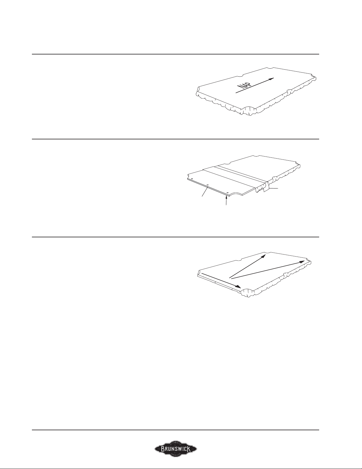
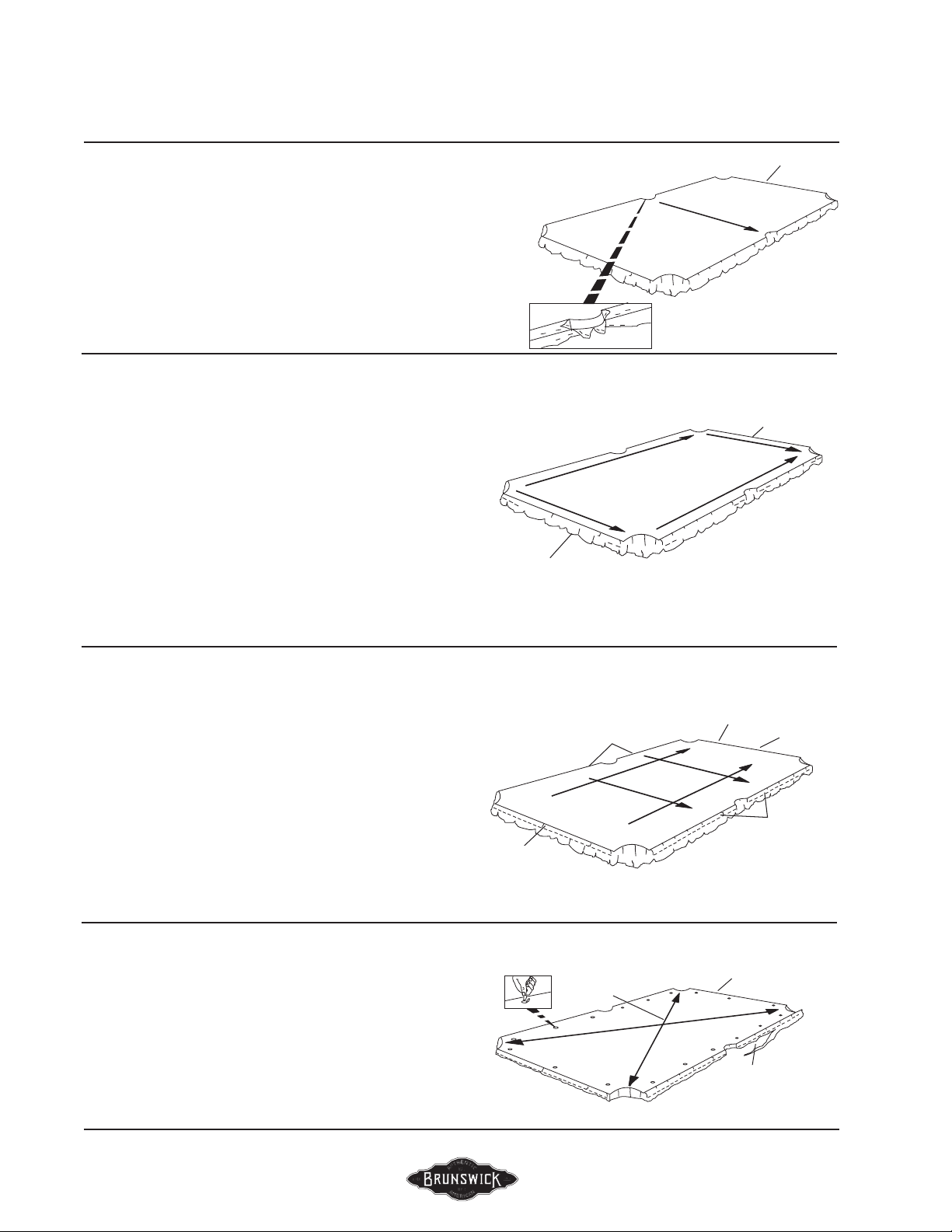
FIGURE FOUR
Step #11: At location #9, cut a short slit in the cloth at
the edge centered on the side pocket opening. Grasp the
cloth rmly above this slit, pull the cloth into the side
pocket opening and tack or staple to the wood frame.
Complete fastening of the cloth to the side pocket
opening, making sure the cloth is tacked or stapled to
the wood frame.
Step #12: Stretching the cloth tightly across the table
from location #9, repeat Step 11 at location #10.
FIGURE FIVE
Step #13: At the head end of the table, tack or staple the
cloth at location #11, maintaining uniform overhang.
Step #14: Pull the cloth from location #11 toward
location #12 and tack or staple securely along the wood
frame, keeping the cloth even along the head end.
Step #15: Stretch the cloth rmly from location #11 to
the foot end of the table and tack or staple at location
#13.
Step #16: Stretch the cloth tightly from locations #12
and #13 toward location #14 and tack or staple securely
along the wood slate frame.
FIGURE SIX
Step #17: Tack or staple all of the left side on 2" centers
keeping the cloth even along the wood frame.
Step #18: Tack or staple the balance of the head end on
2" centers also keeping the cloth even along the wood
frame.
Step #19: Stretch the cloth tightly toward the foot end of
the table, tacking or stapling on 2" centers along the
wood frame at the foot end.
Step #20: Stretch the cloth tightly across the table to the
right side, tacking or stapling on 2" centers all the way
along the wood frame at the right side.
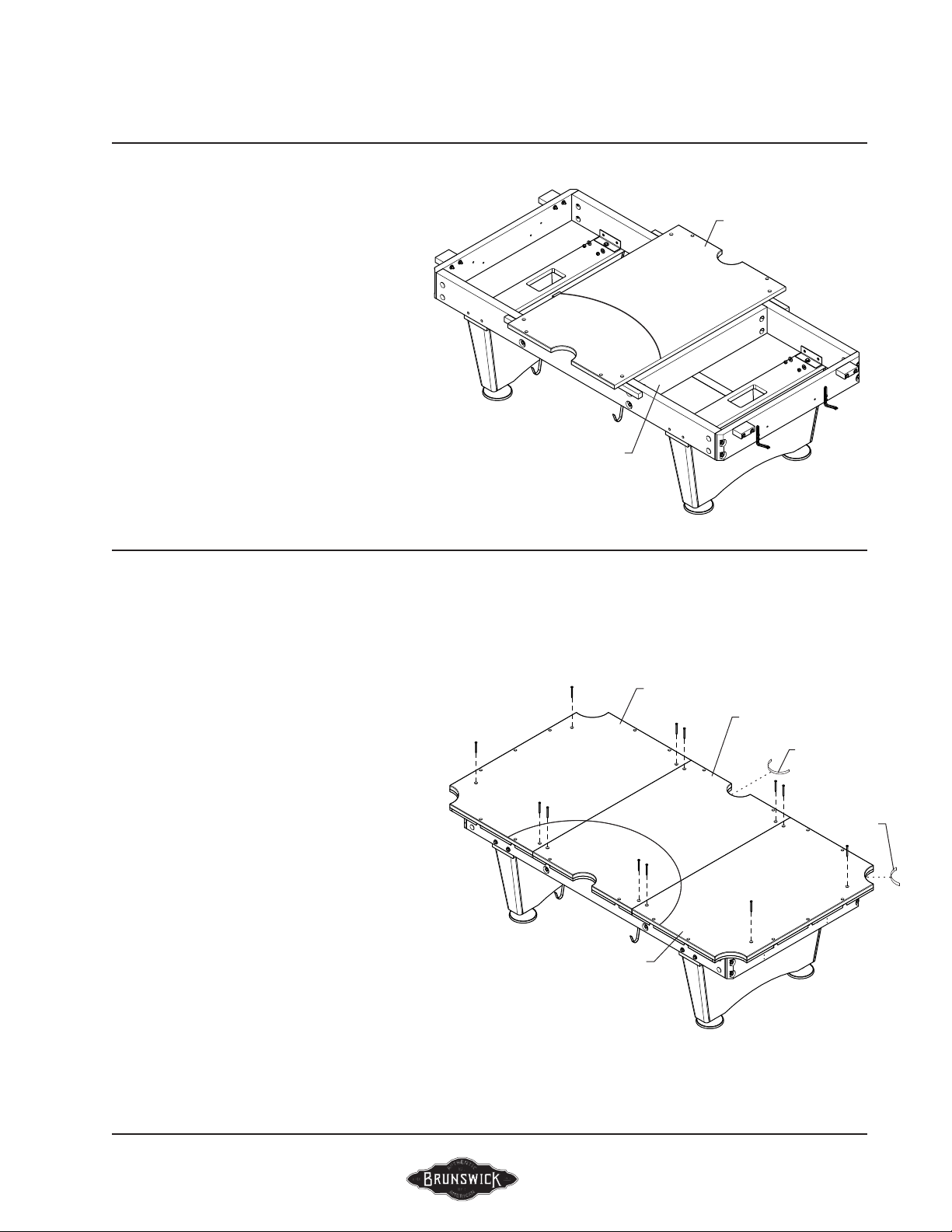
FIGURE SEVEN
Step #21: Stretch the cloth into the corner pocket
openings and tack or staple to the wood slate frame.
Step #22: Trim off excess cloth around the perimeter of
the slate. Locate the eighteen (18) rail attach holes and
cut clearance holes in the cloth with a sharp knife.
NOTE:
Occasionally cloth will stretch, leaving wrinkles
at the pockets. To retighten, remove apron, one end rail
and one side rail. Pull cloth taut, and retack or restaple
along the open end and side to restore original tightness.
FIGURE FOUR
FIGURE FIVE
FIGURE SIX
FIGURE SEVEN
#15
FOOT #17
#18
#16
#13 FOOT
#14
#12
#11
HEAD
#9
FOOT
#10
#19
FOOT
#20
CUT HOLES IN CLOTH AT
RAIL BOTH LOCATIONS

BRUNSWICK INSTALLATION MANUAL PAGE 11
BLACK WOLF PRO
GULLY SYSTEM ASSEMBLY (FOR
RETURN SYSTEM TABLES ONLY)
NOTE:
If table is equipped with gully returns,
proceed to install in the following manner.
FIGURE ONE
FIGURE ONE
Step #1: Place the right-hand foot and gully track into position against
side and end base frame members. Be sure the track is properly positioned
entering the receiver box with the end hanger bracket up against the end
slate attach cleat. All side hanger brackets should be up against the slate
framing. Attach gully track, through hanger brackets, using #12 x 1-1/4”
pan head screws and #12 fender washers. Repeat on opposite side for
left-hand foot end gully track.
Step #2: Place the right-hand head end gully track into position against side
base frame member. Be sure the track is end-to-end with the previously
attached foot end track and all hanger brackets are up against the slate
framing. Attach gully track, through hanger brackets, using #12 x 1-1/4”
pan head screws and #12 fender washers. Repeat on opposite side for
left-hand head end gully track.
Step #3: Attach triangle rack bracket, one per side of the receiver box (pilot
holes provided), using #8 x 3/4” pan head screws and #8 fender washers.
HEAD END GULLY SECTION
(2 REQUIRED/ L.H & R.H)
FOOT END GULLY SECTION
(2 REQUIRED/ L.H & R.H)
#12 x 1-1/4” PAN HEAD SCREW
#12 FENDER WASHER

PAGE 12 BRUNSWICK INSTALLATION MANUAL
BLACK WOLF PRO
RAIL ASSEMBLY
FIGURE ONE
Step #1: Place corner casting upside down on oor. Seat
end and side rail clearance holes onto corner casting
posts.
Step #2: Firmly hold end and side rails together, keep
them, square by using a carpenter’s square against the
cushions.
Step #3: Attach using 1/4-20 x 1” hex head bolt
and 1/4” fender washers.
FIGURE ONE
FIGURE TWO
Step #4: Using the center hole in tie plate, loosely attach
it to the corner casting post using 1/4-20 X 1” hex head
bolt and 1/4” ID fender washer.
FIGURE TWO
FIGURE THREE
Position tie plate and drill four pilot holes. Install four
#10 x 3/4 C.R pan head tapping screws. Tighten
screw installed in step #4.
FIGURE THREE
FIGURE FOUR
Step #5: Thread a stud into the pre-positioned nut
plates inside each rail.
NOTE: Three places per rail.
FIGURE FOUR
!NOTE: DO NOT OVER TIGHTEN
1/4-20 x 1”
HEX HEAD BOLT
CARPENTER’S SQUARE 1/4” FENDER
WASHER
END RAIL
CORNER
CASTING
SIDE RAIL
1/4-20 x 1”
HEX HEAD BOLT
1/4” FENDER
WASHER
TIE PLATE
CORNER CASTING POST
TIE PLATE
#10-3/4” C.R. PAN HEAD
TAPPING SCREW
3/8-16 x 2-3/4” STUD

BRUNSWICK INSTALLATION MANUAL PAGE 13
BLACK WOLF PRO
RAIL AND APRON ASSEMBLY
FIGURE ONE
Step #1: With the rails remaining face down, attach
aprons as shown. Aprons must overhang equally at
each end.
FIGURE ONE
FIGURE TWO
Step #2: Carefully slide an apron corner extrusion over
the ends of the aprons. Attach as shown.
FIGURE TWO
FIGURE THREE
Step #3: Position the rail and apron assembly over the
table as shown. Carefully align the rail studs through
the holes located on the slate.
NOTE: Do not attempt to do this without the aid of
another person.
FIGURE THREE
#12 x 2”
PAN HEAD SCREW
#12 FLAT WASHER
(9/16” O.D.)
APRON CORNER
EXTRUSION
#8 x 1/2” PAN
HEAD SCREW
(CONTINUED)

PAGE 14 BRUNSWICK INSTALLATION MANUAL
BLACK WOLF PRO
RAIL AND APRON ASSEMBLY
(CONTINUED)
FIGURE FIVE
Step #5: Position the side pocket pads and corner
pocket pads in their respective locations. Fit and
trim as required and attach with 1” nails (supplied).
FIGURE SIX
Step #6: Thoroughly brush the area on which the bed
spots are to be applied. Position the bed spot and rmly
roll a ball over the spot to achieve good adhesion.
NOTE:
Bed spots are self adhesive.
FIGURE SIX
FIGURE FOUR
FIGURE FOUR
Step #4: Attach rails securely to table with 3/8-16 x 2-3/
4” threaded studs, dome washers and 3/8-16 hex nuts.
FIGURE FIVE
3/8-16 HEX NUT
DOME WASHER
1” NAIL
FOOT
SPOT
HEAD
SPOT

BRUNSWICK INSTALLATION MANUAL PAGE 15
BLACK WOLF PRO
BALL RECEIVER BOX ASSEMBLY
FIGURE TWO
FIGURE ONE
Step #1: Securely attach the ball receiver box to the base
frame end sill as shown with four 1/4-20 x 2-3/4” hex
head screws.
FOR RETURN SYSTEM TABLES ONLY
Step #2: Attach triangle rack bracket, one per side of the receiver box (pilot
holes provided), using #8 x 3/4” pan head screws and #8 fender washers.
FIGURE ONE
1/4-20UNC TEE-NUT
1/4 FLAT WASHER
1/4-20 x 2-3/4”
HEX HEAD SCREW
BALL RECEIVER BOX
BALL RECEIVER BOX
TRIANGLE RACK BRACKET
#8 FENDER WASHER
#8 x 3/4” PAN HEAD SCREW
FIGURE TWO
Table of contents
Popular Board Game manuals by other brands

Lagoon
Lagoon 440 owner's manual

Millennium
Millennium Europe Chess Champion M800 user manual

Outdoor Play
Outdoor Play Memo 2020 instruction manual

Fundex Games
Fundex Games El Chavo Loteria Loteria User instructions

Milton Bradley
Milton Bradley Battleship instructions

DMI Sports
DMI Sports HT505 instructions