manuals.online logo
Brands
  1. Home
  2. •
  3. Brands
  4. •
  5. Bryant
  6. •
  7. Thermostat
  8. •
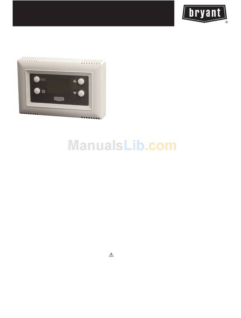
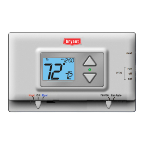
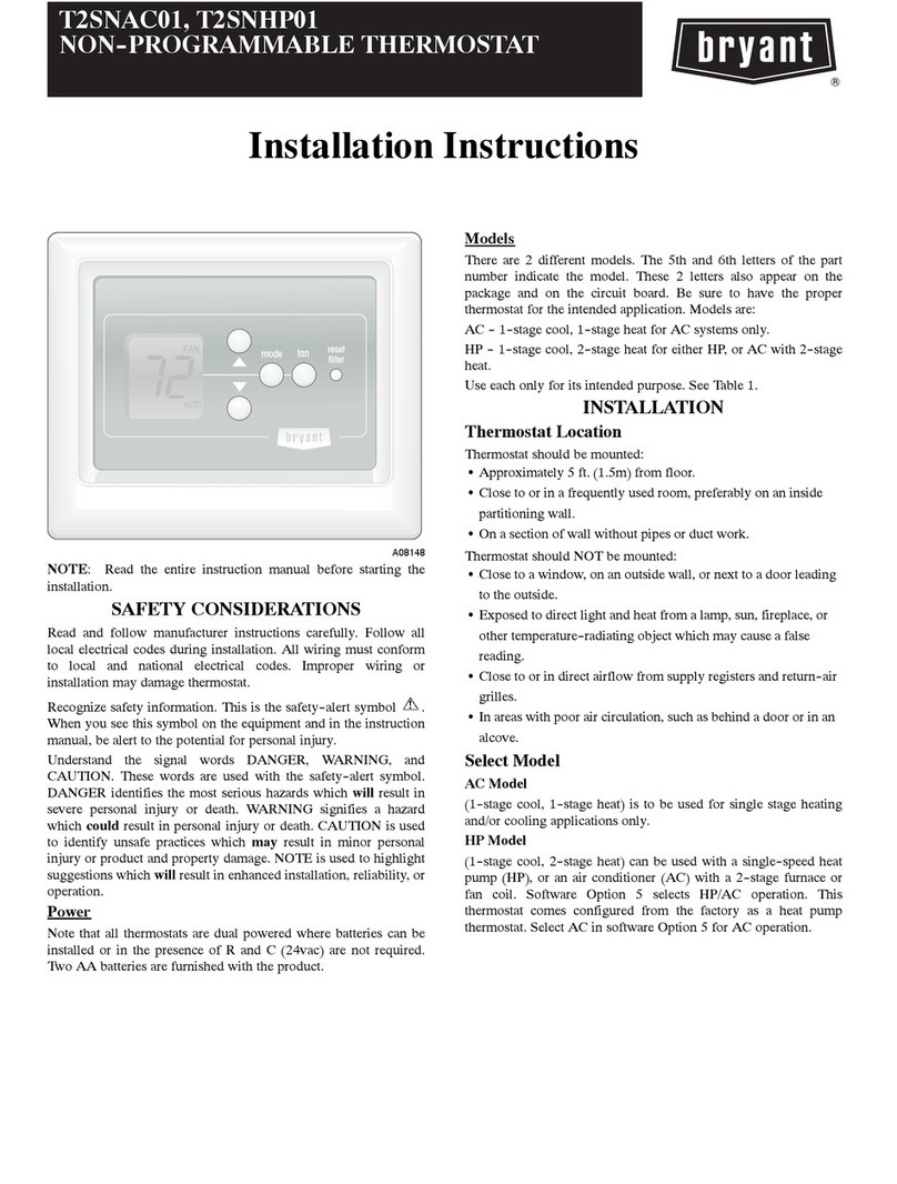
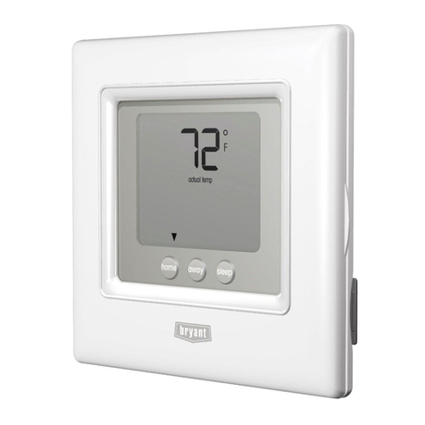
  9. Bryant TSTATCCNB001 User manual

Bryant TSTATCCNB001 User manual

This manual suits for next models

1

Other Bryant Thermostat manuals

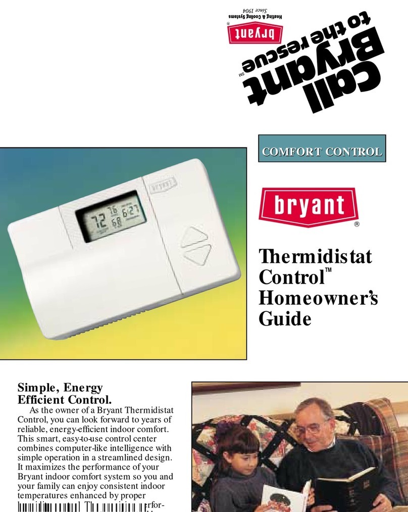
Bryant TSTATCCPS101 User manual

Bryant

Bryant TSTATCCPS101 User manual

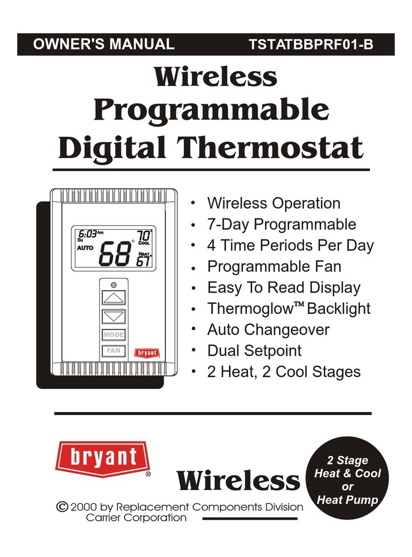
Bryant TSTATBBPSP2-WC Dimensions and installation guide

Bryant

Bryant TSTATBBPSP2-WC Dimensions and installation guide

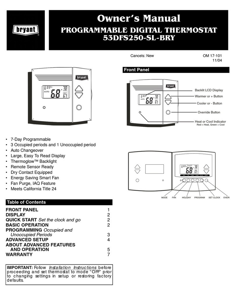
Bryant Legacy Series User manual

Bryant

Bryant Legacy Series User manual

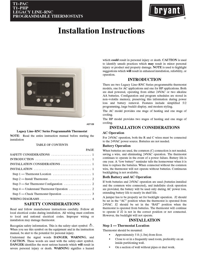
Bryant LEGACY T2-PAC User manual

Bryant

Bryant LEGACY T2-PAC User manual

Bryant T2--WHS01 User manual

Bryant

Bryant T2--WHS01 User manual

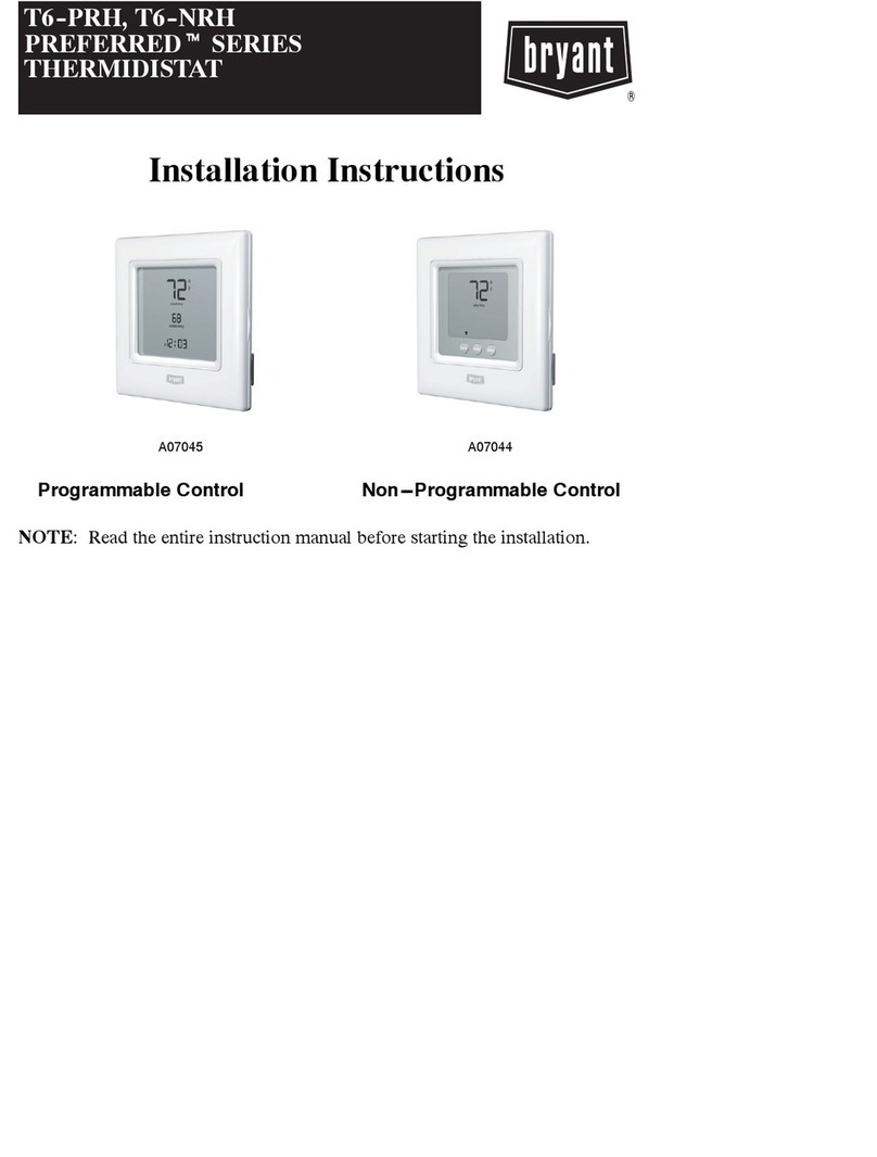
Bryant PREFERRED T6-NRH User manual

Bryant

Bryant PREFERRED T6-NRH User manual

Bryant TSTATBBP071-01 Dimensions and installation guide

Bryant

Bryant TSTATBBP071-01 Dimensions and installation guide

Bryant T1--NAC User manual

Bryant

Bryant T1--NAC User manual

Bryant Programmable Thermidistat User manual

Bryant

Bryant Programmable Thermidistat User manual

Bryant TSTATCCPB101 User manual

Bryant

Bryant TSTATCCPB101 User manual

Bryant TSTATBBP250-01 Dimensions and installation guide

Bryant

Bryant TSTATBBP250-01 Dimensions and installation guide

Bryant NON-PROGRAMMABLE THERMOSTAT User manual

Bryant

Bryant NON-PROGRAMMABLE THERMOSTAT User manual

Bryant PREFERRED T6-NAC User manual

Bryant

Bryant PREFERRED T6-NAC User manual

Bryant 53DFST2-NP-BRY User manual

Bryant

Bryant 53DFST2-NP-BRY User manual

Bryant TSTAT Assembly instructions

Bryant

Bryant TSTAT Assembly instructions

Bryant Preferredt Series User manual

Bryant

Bryant Preferredt Series User manual

Bryant EVOLUTION Zone Control SYSTXBBUIZ01-B User manual

Bryant

Bryant EVOLUTION Zone Control SYSTXBBUIZ01-B User manual

Bryant T2-PAC01-A User manual

Bryant

Bryant T2-PAC01-A User manual

Bryant TSTATBBPS701 Guide

Bryant

Bryant TSTATBBPS701 Guide

Bryant TSTATBBNQ001 Guide

Bryant

Bryant TSTATBBNQ001 Guide

Bryant ZONE PERFECT PLUS Guide

Bryant

Bryant ZONE PERFECT PLUS Guide

Bryant IIT2-WHS-02 User manual

Bryant

Bryant IIT2-WHS-02 User manual
Bryant PROGRAMMABLE DIGITAL TERMOSTAT OM 17-101 User manual

Bryant

Bryant PROGRAMMABLE DIGITAL TERMOSTAT OM 17-101 User manual

Bryant AND THERMIDISTAT CONTROL Assembly instructions

Bryant

Bryant AND THERMIDISTAT CONTROL Assembly instructions

Popular Thermostat manuals by other brands

Full Gauge TIC-17C product manual

Full Gauge

Full Gauge TIC-17C product manual

Imit Chronomix S manual

Imit

Imit Chronomix S manual

ChiliTec ST-35 ana instruction manual

ChiliTec

ChiliTec ST-35 ana instruction manual

Salus VS05 Installer's/user's manual

Salus

Salus VS05 Installer's/user's manual

Azel D-500 user guide

Azel

Azel D-500 user guide

Honeywell Chronotherm III owner's manual

Honeywell

Honeywell Chronotherm III owner's manual

Charmeg MP-R user manual

Charmeg

Charmeg MP-R user manual

dixell WING XW40LS Installing and operating instructions

dixell

dixell WING XW40LS Installing and operating instructions

Network Thermostat NetX X7C-WIFI Installation and programming manual

Network Thermostat

Network Thermostat NetX X7C-WIFI Installation and programming manual

Radio Thermostat CT80 Operation guide

Radio Thermostat

Radio Thermostat CT80 Operation guide

HAI Omnistat RC-120 installation manual

HAI

HAI Omnistat RC-120 installation manual

Lennox iComfort E30 Installation and setup guide

Lennox

Lennox iComfort E30 Installation and setup guide

Lux Products PSD011Ba Installation and operating instructions

Lux Products

Lux Products PSD011Ba Installation and operating instructions

Computherm Q20 operating instructions

Computherm

Computherm Q20 operating instructions

Heatmiser neoStat user manual

Heatmiser

Heatmiser neoStat user manual

Mars HEAT CONTROLLER IR Wireless Thermostat user manual

Mars

Mars HEAT CONTROLLER IR Wireless Thermostat user manual

LUX LP0511D user manual

LUX

LUX LP0511D user manual

Saswell SAS920XWHB-7-S-RF User manual and warranty card

Saswell

Saswell SAS920XWHB-7-S-RF User manual and warranty card

manuals.online logo
manuals.online logoBrands
  • About & Mission
  • Contact us
  • Privacy Policy
  • Terms and Conditions

Copyright 2025 Manuals.Online. All Rights Reserved.

Installation Instructions
TSTATCCNB001
TSTATBBNB001
P474-0100 Digital Thermostat
NOTE: _od tne e_lm _l=_dton rt,_tu_ k_,0_ tu=l_ _e i_,_blion.
O
HEAT
COOL
&
HEAT
PUMP
MULTI-STAGE-NON-PROGRAMMABLE
IM-TSTAT-17 _ _ in U_A_ Clit_og NO. 131_-TA33
PREPARATION 2
REMOVE OLD THERMOSTAT 3
INSTALL BACKPLATE & WIRE 4
WIRING DIAGRAMS 5
CALIBRATION 8
TEST OPERATION 9
TROUBLESHOOTING 10
CAUTION FollOw Installation Instructions carefully.
DISCONNECT POWI_RTOTHEHF..AII_R-
AIR CONDITIONER BEFOREREMOV1NG
THEOLD THERMOSTATAND INSTALLING
THENEWTHER_A_ WARNING
Replacement Components Dlvtsion (_) Carrier CorlporaUon 4/01
This device complies with Part 15 of the FCC rules.
Operation is subject to the following 2 conditions:
(1) This device may not cause harmful interference,
and (2) This device must accept any interference
received, including interference that may cause
undesired operation.
FQgel
@
@
Proper installation of the thermostat will be
accomplished by following these step
by step instructions. If you are unsure
about any of these steps, call a qualified
technician for assistance.
Assemble tools as shown below.
(when not using
Flat Blade Wire cutter j-box)
Screwdriver &Stripper
Make sure your Heater/Air Conditioner
is working properly before beginning
installation of the thermostat.
@Carefully unpack the thermostat.
Save the screws, wall anchors, and
instructions.
Poge 2
@
@
@
Turn off the power to the Heating/Air
Conditioning system at the main fuse
panel. Most residential systems have
a separate breaker for disconnecting
power to the furnace.
Remove the cover of the old thermostat.
If it does not come off easily check for
screws.
Loosen the screws holding the thermostat
base or subbase to the wall, and lift away.
@
Disconnect the wires from the old
thermostat. Tape the ends of the wires
as you disconnect them, and mark them
with the letter of the terminal for easy
reconnection to the new thermostat.
Keep the old thermostat for reference
purposes, until your new thermostat is
functioning properly.
Poge3
Remove the backplate connector from the
rear of the thermostat. Install wires as directed
below. When finished, snap thermostat on to
backplate.
If the terminal designations on your old
thermostat do not match those on the
new thermostat, refer to the chart below,
or the wiring diagrams that follow.
Function
Fan
Cooling
Heating
Power
Common
Rev. Valve
2nd Stage Cool
2rid Stage Heat
RemOteSaP'_o¢÷5vdc
RemoteSensorSignal
Remo_Ser*_rG_und
DpjContactSv_h 1
DryCoetactSvat_2
Wire from the
old therr'nostat
terminal marked
GorF
Y1,YorC
Wl,Wor H
Rh, R, M, Yr, A
C
o/e
Y2
w2
RS+5
RS
RS G
CK1
CK2
Install on the
new thermostat
connector marked
G
Y1
WI,0,B
R
C*
Wl ,O,B**
Y2
W2
* C may not be used on all systems.
** O/B is used ifyour system is a Heat Pump.
Page 4
5 Wire, 1 Stage Cooling, 1 Stage Gas Heat
0
Wl YI G C
I
Reskleflt_al Gas or Ele_ic Heat *,
Bectric Cool, split systems & package
units
24 vac common
fan ml__v
comoressor I_IAv
1st stage heat circuit
24 vac return
*ff using electric heat this option must be
selected on during advanced setup.
>-<
>-<
>.<
>-<
L
E
C
G
Y1
O
Wl
R
Y2
N2
4 W]m, 1 Stage Co_lng, 1 Stage Gas Heat
O
W2Y2 1_I G C
rResidenital G_ of Ele_ Heat *,
Elec_ic Cod1 _t SyStIBm_a pac_cJ__
un_
fan relay
cornDressorrelav
1st stage heat circuit
24 vac mtum
>-<
>_I
L
E
C
G
Yf
0
_41
R
_2
_2
•ffusingelectricheat this opti_ mustbe
selectedcn duringadvanced_etup.
Pog_ 5
6 Wire, 2 Stage Cooling, 1 Stage Heat
W2 ¥2 0
Wl YI GC
bl Resi(JentJad2 Stage Coc4ing, with
Gas or Bect_ Heaff'
24 vac common
fan relay
comomssor relay
1st staoe heat circuit
24 vac retum
2nd sta_e compressor relay
•If using electric heat, this option must
be selected during advanced setup.
>-<
><
,X
p-<
>-<
>-<
>-<
>-<
>-<
$ Wire, 1 Stage Cooling, 2 Stage Heat Reside_al &cof_merdal1Stage Cooling,
wi_ 2 Stage GasorE_ctdc Heat*
Thermostat
24 vac common
fan relav
comDre_or relay
1st staae heat drcuit
24 vac retum
W2Y2 R \
X
>-<
>-<
>-<
>_
X
>-<
X
>-<
.J
L
E
C
G
Y1
O
N1
R
f2
L
E
C
G
YI
iw°,
"{2
_)nd _tng_ hnnt ,"Jr,'Jilt W2
_ge6
7 Wire, 2 Stage Cooling, 2 Stage Heat
O
W2_2 Wl Y1 G C
** Comm_m_lal heat Dum_ do not have
_e heat pump tumed on in advanced setup,
P_.,_mnerc_l Gas 0€ Electdc Heat _,
Ekectric Cod, split sys_ns & package units
k_uding Commen_ial Heat Pumps"
Thermostat
24 vac common
fan rel__v
comDmssor relay
L
>'< E
>< C
_>'< G
P'< Y1
>.,< O
I st staae heat ciroJit P< Wl
24 vac return >'< iR
2nd staae comDressor relay X
2nd _t_ne h_t PJmld_ >_
_lfusingelec_heat,_isop_nmust __
5 Wire, 1 Stage Cooling, 1 Stage Heat - Heat Pump*
O
W2 Y2 R Wl YI G C Noamdr_ryheat._side_l_alHeatPumps.
splitsystems& packageunits
Thermostat
24 raG common
fan rainy
cornoressor relay
mversina valve
:)4 v_c return
*ff using _t#j2_ll hemt pump, thi_ op#on
muM be _l_ted on dunng Bdvanced setup.
Poge 7
L
E
C
>-< G
Y1
O
>-< Wl
R
Y2
N2
6Wire, 1Stage Cooling, 2 Stage Heat, Heat Pump *
OMostresiden6alsplitandpackageheatpumps
W2 Y2 Wl Y1 G C withauxiliar/heat
24 vac common >'<
fan rnlAy >'<
compressor relav >"<
let staon heat circuit >'<
>-<
24 vac return >'<
>.,<
*The heatpumpopUonmustbe selected
on duringadvancedsetup.
_nd _tnn_ hnnt r.ir_J i_t :X
L
E
C
G
Y1
O
R
Y2
N2
Everythermostatiscalibratedbeforeit leavesthe factory.
Undernon_alcircumstances there willneverbe a need to
recalibratethe thermostatagain.
To ao=ommodatespecial needs,the thermostat maybe recalibrated
following these steps:
1. While holding the mode button in. press the down button for
2 seconds. After all the icons in the display appear, release
the buttons.
2. Press the mode button.
3. Press the up or down buttons until the flashing number
equals the cumont room temperature.
4. Press the mode button to return to normal operation.
Poge8
Turn the power on to the Heating/Air
Conditioning system.
@
@
Press the MODE button repeatedly until
the HEAT icon appears on the display.
Press the Up or Down buttons until the set
temperature is 10 degrees above room
temperature. The furnace should turn on.
Press the MODE button repeatedly until
the COOL icon appears on the display.
Press the Up or Down buttons until the set
temperature is 10 degrees below room
temperature. The air conditioner should
turn on. NOTE: Most equipment has a
time delay of 5minutes between cool
cycles. This feature is defeatable on the
thermostat. Consult the Owner's Manual
under Setup, cycles per hour.
Press the MODE button to OFF. Press
the FAN button to Fan On. The fan
should turn on and run continuously.
Poge9