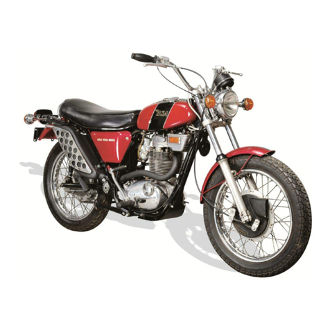
PREPARINC TFTE MACHINE
RAMOVING THE MOTOR.CYCLE FROM TI{E CASE
Check tlrrit the packing case is ttre RIGI-lT WAY UP before disrnantling. The TOF has stencilled markings
o* it, the bottorn does not.
Prise off the top boards rvith a suitable pinch bar anel take out the top packing material. Take off
one sirJe of the case and remove the four wooden packing case supports from the top.
Note that one support is held by two holted brackets to the lr:rndlebar clamp lugs. The rear support
carries the front ancl rear sat'ety bars, but these may be left attached to the support until they are to be fitted
to the motor-cycle.
Carefully withdraw the machine ltonr the case and check that you have all the loose parts before
discarding the wrappings. lletain the Test Cartl in case you mny fincl it necessary to report any loss of parts
or clamage clirring transit, Small items, such as the footrests, handlebar clanrp brackets. etc., ivill be found
in the pannier bag. The saddle and windscreen assembly are each paeked separately.
Put the machine on to its centre stand ancl proceed to fit the loose eornponents.
Norr:-lt is rnost important that nel selt'-locking nuts are used during assembly. Once a nrit ol this
type has been used, the locking device becomes inoperative, rendering the nut unfit for further use.
FTTTII\G THE }I,ANDLE8AR
Place the handlebar, complete ivith corrtrols and cables, in position and fit the clamp brackets loosely'
When a suitable handlebar position has been determined, the f'our clamp fixing bolts can be tightened.
Check each control for correct operatiou and make adjustments as neces$ary.
FITTING TT{E SAFETY B.A.RS
Detach the safety bars tiom the packing case rear support. which will have been remr"rved during case
clisrnantling"
Flace the front safety bar in position against the frame down-tube and attach loosely 1o the loiver
holes in the steering head plates. using one bolt" spacer (between the plates) and nut. Take out the front
engine mounting bolt which also secures the exhaust pipe trracket. The spacer on the bolt is only fitted
tbr packing purposes and should now be discarded.
Locate the lower brackets of the s:rfet1, bar over the engine mounting lug and securer together with
the exhaust pipe bracket, with the nut dnd bolt. The top llxing bolt can now be tightenecl futly. Finally.
connect the brown/blue and brown/black leads to their respective terminals on the horn.
The rear salety bars are in two li*lves and can only tre fixed together when in position below the saddle
support rail. Ensure that tlre bars are the correct way round, i.e.. fixing plates angled to the front" befcrre
securing together with the two "Nyloc" nuts and washers. Pass the two "U" bolts over the sacldle support
rail at each side and fix loosely to the safety bars with four "Nyloc" fluts and washers. The angleii fixing
plates should now be secured to the lugs on the sub-fiame, using the existing nuts and bolts. Note that
the right-hand bolt also reiains the exhaust pipe bracket.
Finally, tighten all the fixing bolts and nuts and check for rigidity.
FTT-TTNC THE SADDLE
Engage the front bracket, beneath the saddle. with the frame tie-bar and locate the rear fixing studs with
the support rail brackets. R.each belorv the saddle at the rear and fit the spacers, washers and nuts on to
the studs. T'igliten the nuts evenly ancl cheek that the saddle is secure.
Page 7
