BSH Pro Harmony 304 Operating instructions

Concerning this document................................................................3
1.1 Important information.......................................................................................3
1.1.1 Purpose..............................................................................................3
1.1.2 Target group.......................................................................................3
1.1.3 Other applicable documents ................................................................3
1.2 Explanation of symbols ....................................................................................3
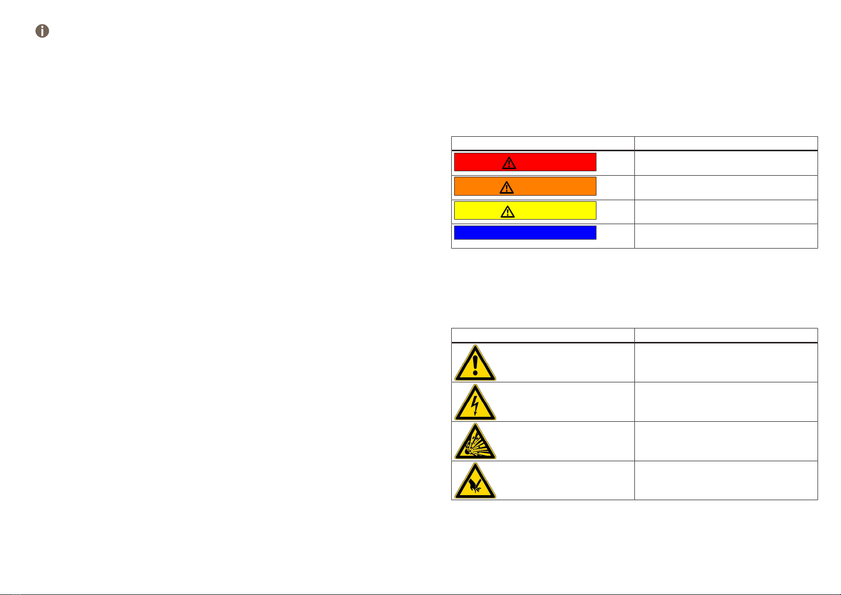
1.2.1 Danger levels......................................................................................3
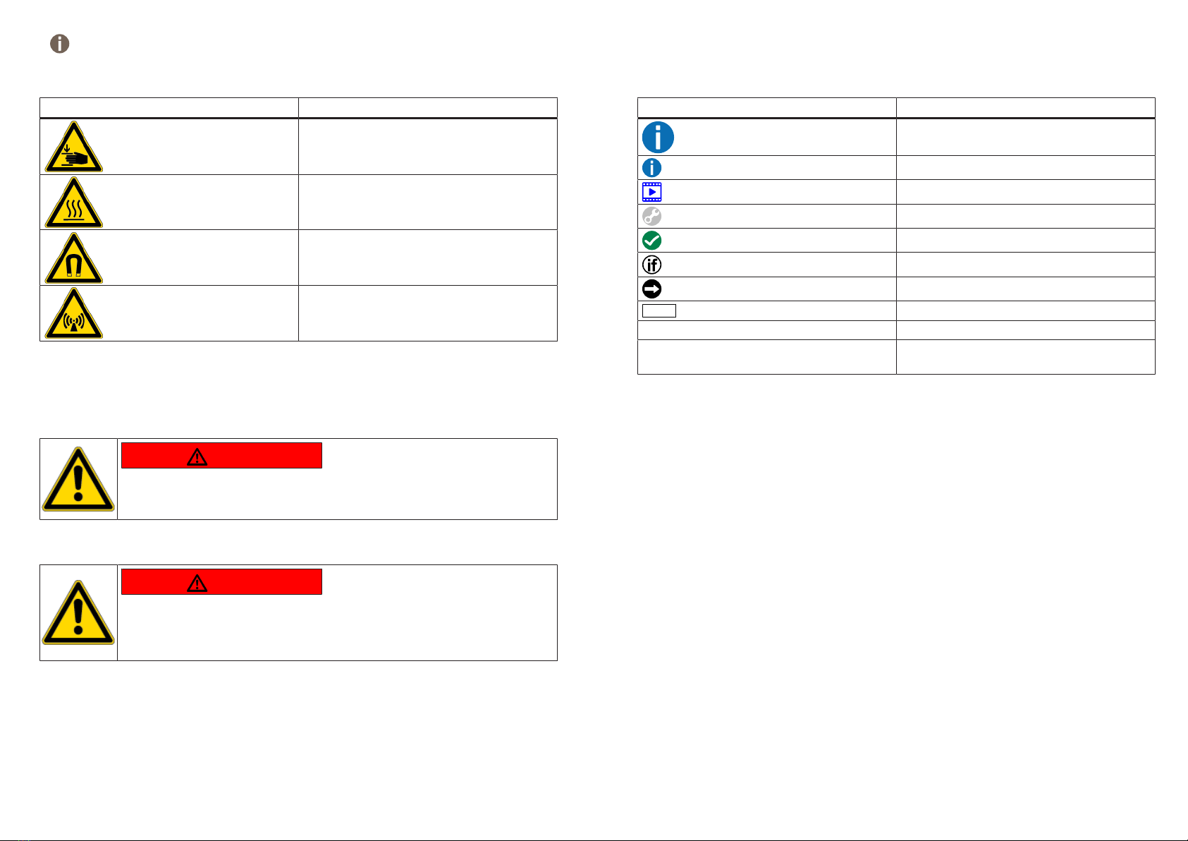
1.2.2 Hazard symbols ..................................................................................3
1.2.3 Structure of the warnings.....................................................................4
1.2.4 General symbols.................................................................................4
Safety.........................................................................................................5
2.1 Qualification ....................................................................................................5
2.2 General safety instructions...............................................................................5
2.2.1 All domestic appliances.......................................................................5
2.3 Measures after each repair ..............................................................................6
Design and function.............................................................................7
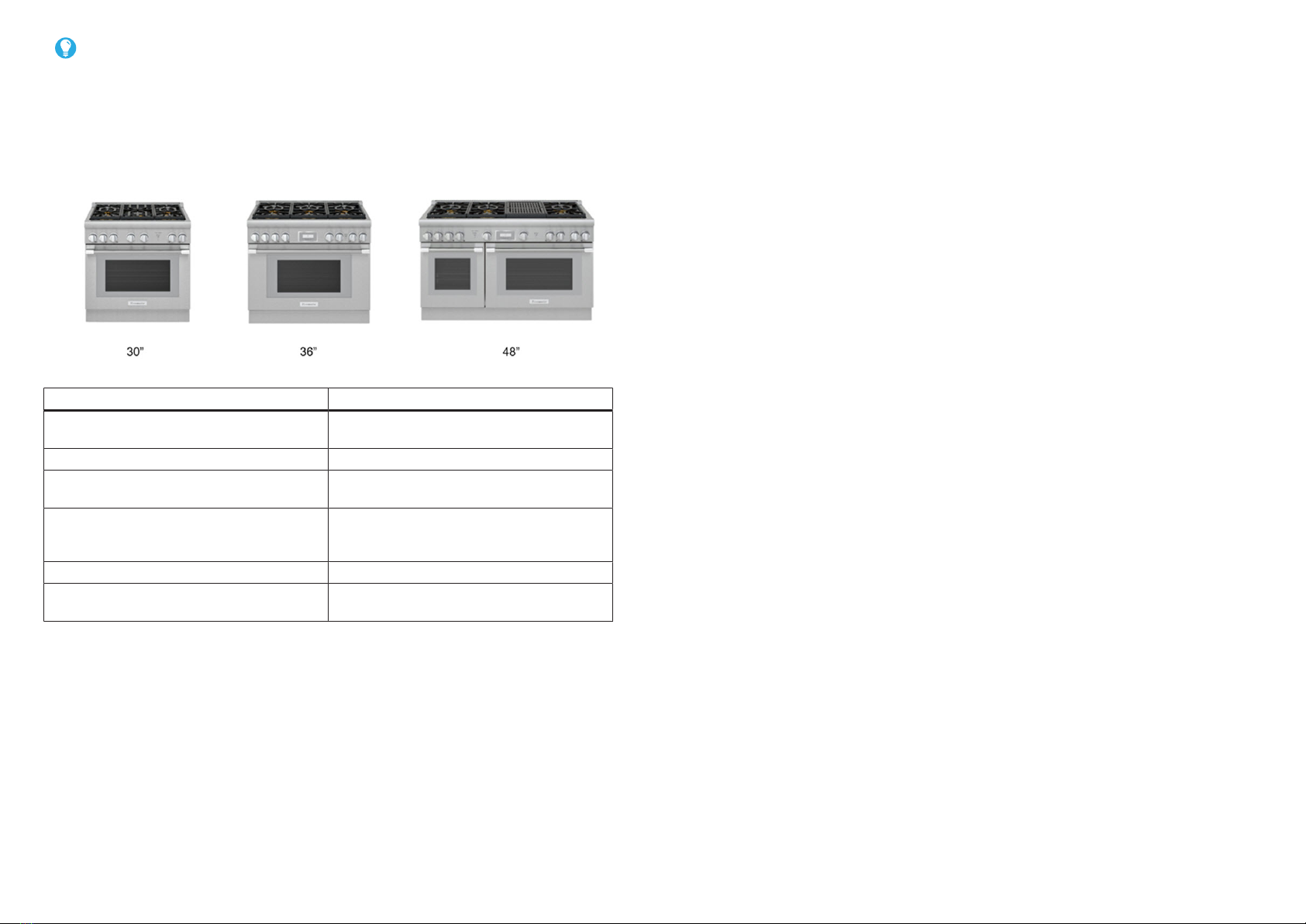
3.1 Pro harmony ...................................................................................................7
3.2 Pro harm topview ............................................................................................8
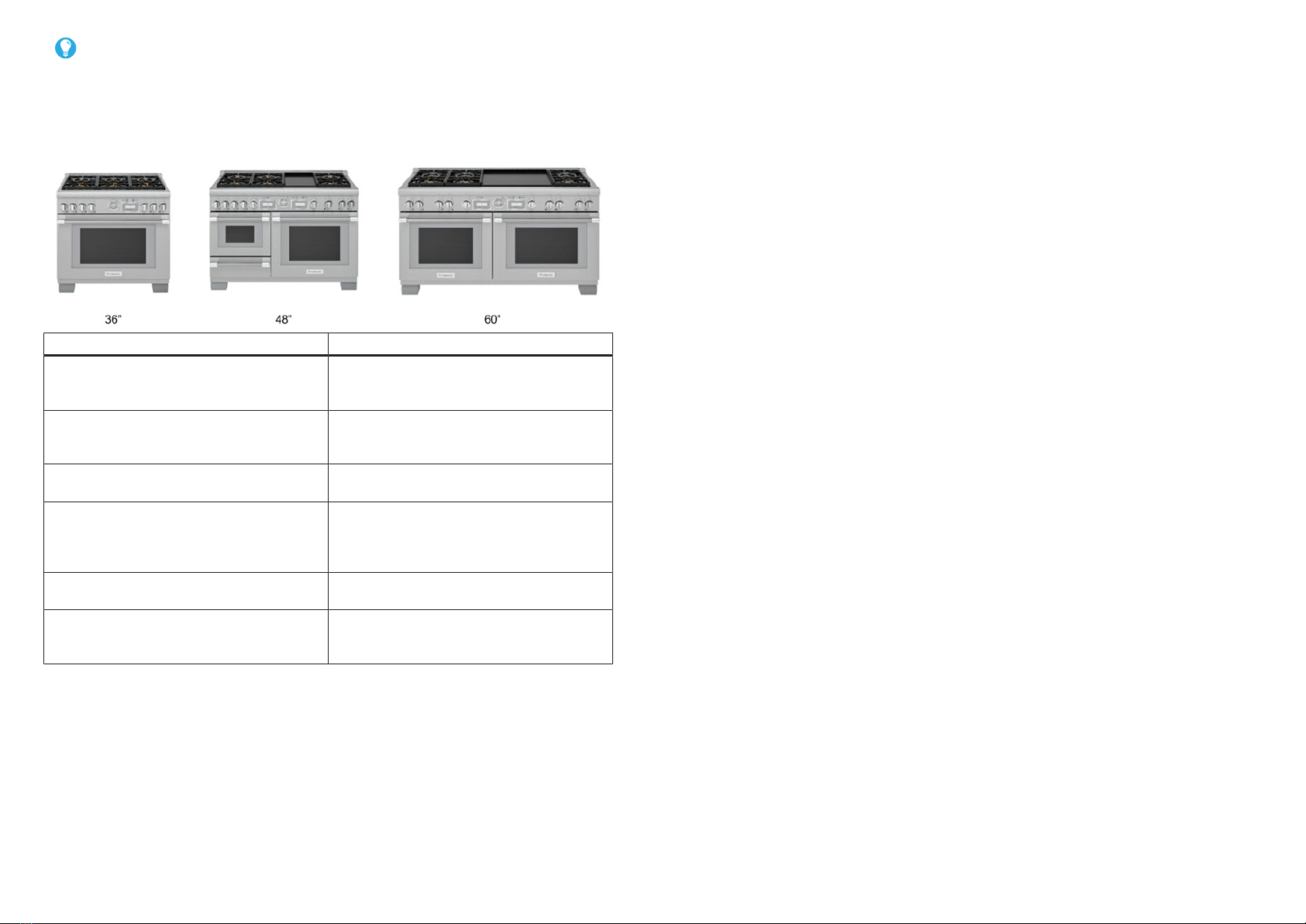
3.3 Pro Grand .......................................................................................................9
3.4 Pro Grand topview.........................................................................................10
3.5 Operation of STAR burners............................................................................11
3.6 Extra Low STAR Burners ...............................................................................12
3.7 Main oven interior ..........................................................................................14
3.8 Operation of STAR burners............................................................................15
3.9 Soft-close device in oven carriage ..................................................................16
3.9.1 Oven carriage is closed.....................................................................16
3.9.2 Oven carriage is pulled in ..................................................................17
3.9.3 Oven carriage is closed.....................................................................17
3.9.4 Oven carriage is open .......................................................................18
3.9.5 Oven carriage is open .......................................................................18
3.10 Components Rangetop ..................................................................................20
3.11 Meat temperature probe (NTC).......................................................................21
3.11.1 Single-point meat temperature sensor ................................................21
3.11.2 Multipoint meat temperature probe.....................................................21
3.12 Electric grill components ................................................................................22
3.13 Leads removed must be reinstalled on the same terminal it was removed
from. ..............................................................................................................23
3.14 iService icons .................................................................................................24
Fault Diagnosis ....................................................................................26
Malfunction.....................................................................................................26
Burner flame goes out .....................................................................................26
Igniter fails to ignite ........................................................................................26
Steam oven leaking when door is open ............................................................26
Steam oven Door not sealing properly..............................................................26
Too little water in steam oven properly .............................................................26
Too much water in steam oven ........................................................................26
No steam in cavity...........................................................................................27
Water not boiling.............................................................................................27
Test ...........................................................................................................28
5.1 Burner and Ignition..........................................................................................28
Repair.......................................................................................................30
6.1 Replacing grill 18 ............................................................................................30
6.2 Replacing griddle 18 .......................................................................................33
6.3 Replacing parts under rangetop .......................................................................36
6.4 Replacing backguard panels............................................................................39
6.5 Adjusting natural gas burner valves..................................................................40
6.6 Replacing range panels...................................................................................42
6.7 Replacing steam back panels ..........................................................................43
6.8 Reasembly door skins .....................................................................................44
6.9 Replacing heat shield ......................................................................................45
6.10 Replacing burner support rail ...........................................................................46
6.11 Replacing jet holder ........................................................................................48
6.12 Replacing ignition device.................................................................................50
6.13 Replacing Thermal Fuse .................................................................................51
6.14 Replacing Meat Probe.....................................................................................52
6.15 Replacing control panel Ranges ......................................................................54
6.16 Replacing standard valve ................................................................................57
6.17 Replacing XLO valve 18 ..................................................................................59
6.18 Replacing spark module ..................................................................................62
6.19 Replacing solenoid valve .................................................................................64
Repair manual-Free standing cooker
2019-04-13_58300000217218_ara_en_a Copyright by BSH Hausgeräte GmbH Page1of85

6.20 Replacing HC module range ..........................................................................66
6.21 Replacing manifold ........................................................................................67
6.22 Replacing regulator 2018 ...............................................................................69
6.23 Replacing Oven Temp Gauage ......................................................................70
6.24 Replacing cooling fan ....................................................................................71
6.25 Replacing Thermostat....................................................................................72
6.26 Replacing temp sensor Lg..............................................................................73
6.27 Replacing Range LED indicator......................................................................74
6.28 Replacing oven door......................................................................................75
6.29 Replacing oven in and outter door ..................................................................76
6.30 Aligning the door ...........................................................................................77
6.31 Replacing covection oven parts......................................................................78
6.32 Replacing oven bulb ......................................................................................80
6.33 Replacing broil element..................................................................................81
6.34 Replacing bake element.................................................................................84
Repair manual-Free standing cooker
2019-04-13_58300000217218_ara_en_a Copyright by BSH Hausgeräte GmbH Page2of85

Concerning this document
1.1 Important information
Read and observe chapter 2 "Safety" before performing any work!
1.1.1 Purpose
These repair instructions form the basis for a systematic and safety conscious proced-
ure for the repair of domestic appliances.
These repair instructions include information about troubleshooting and repair.
1.1.2 Target group
These repair instructions are intended for persons who are familiar with equipment
technology and were instructed by BSH or an authorised body:
¡Service technicians for the repair of domestic appliances
¡Pre-assemblers in the spare part stockroom when determining required spare
parts
¡Call centre employees during order acceptance
1.1.3 Other applicable documents
The following documents include additional relevant repair information:
¡General repair instructions
¡Error codes and service programs
¡Circuit diagrams
¡Exploded drawings
¡Parts lists
¡Repair videos
1.2 Explanation of symbols
1.2.1 Danger levels
The warning levels consist of a symbol and a signal word. The signal word indicates
the severity of the danger.
Warning level Meaning
Danger Non-observance of the warning message
will result in death or serious injuries.
Warning Non-observance of the warning message
could result in death or serious injuries.
Caution Non-observance of the warning message
could result in minor injuries.
Notice Non-observance of the warning message
could result in damage to property.
Table1: Danger levels
1.2.2 Hazard symbols
Hazard symbols are symbolic representations which give an indication of the kind of
danger.
The following hazard symbols are used in this document:
Hazard symbol Meaning
General warning message
Danger from electrical voltage
Risk of explosion
Danger of cuts
Concerning this document
2019-04-13_58300000217218_ara_en_a Copyright by BSH Hausgeräte GmbH Page3of85

Hazard symbol Meaning
Danger of crushing
Danger from hot surfaces
Danger from strong magnetic field
Danger from non-ionizing radiation
Table2: Hazard symbols
1.2.3 Structure of the warnings
Warnings in this document have a standardised appearance and a standardised struc-
ture.
Danger
Type and source of danger!
Possible consequences of ignoring the danger / warning.
▶Measures and prohibitions for preventing the danger.
The following example shows a warning that warns against electric shock due to live
parts. The measure for avoiding the danger is mentioned.
Danger
Risk of electric shock due to live parts!
Death by electrocution
▶Disconnect appliances from electrical supply at least 60 seconds
before starting repairs.
1.2.4 General symbols
The following general symbols are used in this document:
Gen. symbol Meaning
Identification of a special tip (text and/or
graphic)
Identification of a simple tip (only text)
Identification of a link to a video tutorial
Identification of required tools
Identification of required preconditions
Identification of a condition (if ..., then ...)
Identification of a result
Start Identification of a key or button
[00123456] Identification of a material number
Status Identification of displayed text / window
(in the appliance's display)
Table3: General symbols
Concerning this document
2019-04-13_58300000217218_ara_en_a Copyright by BSH Hausgeräte GmbH Page4of85

Safety
2.1 Qualification
In Germany, only qualified electricians trained by BSH or an authorised body may per-
form any repair work.
In other countries, only similarly trained qualified personnel is permitted to perform the
repair work.
Appliances must only be repaired by persons that are qualified, approved and trained
by BSH or an authorised body as instructed.
2.2 General safety instructions
2.2.1 All domestic appliances
Risk of electric shock due to live parts!
¡Disconnect the appliance from the mains for at least 60 seconds before starting
work.
¡Do not touch the housing, components and cables.
¡For tests on an energised system, use a residual current circuit breaker.
¡Discharge high-voltage capacitors.
Risk of injury from sharp edges!
¡Wear protective gloves.
Risk of injury when dealing with harmful substances!
¡Observe the associated safety data sheet!
Risk to the appliance's safety / function!
¡Only use original spare parts.
Risk of damage to electrostatically sensitive components (ESDs)!
¡Before touching ESDs, use an electrostatic protection system (wristband with earth
safe plug).
¡Do not touch connections and conductor paths of the modules.
¡Only transport ESDs in conductive materials or original packaging.
¡Keep ESDs clear of electrostatically chargeable materials (i.e. plastic).
Safety
2019-04-13_58300000217218_ara_en_a Copyright by BSH Hausgeräte GmbH Page5of85

2.3 Measures after each repair
If the appliance is functional:
¡Check according to VDE 0701 or country-specific regulations.
¡Check external appearance, function and tightness.
¡Document repair work, measured values and functional reliability.
If the appliance is not functional:
¡Identify the appliance as “not functionally reliable”.
¡Warn customers of commissioning and notify them in writing .
Safety
2019-04-13_58300000217218_ara_en_a Copyright by BSH Hausgeräte GmbH Page6of85

Design and function
3.1 Pro harmony
Pro Harmony product lineup.
Size Features
30" 1 Telescopic Rack Std. Temp. Probe 2
XLO Burners
30" Surface Configurations 4 Burner 5 Burner
36 +3 Telescopic Racks +TFT Interface +
Home Connect Enabled
36 Surface Configurations +6 Star Burners +12” Indoor Grill Module
& 4 Burners +412” Griddle Module & 4
Burners
48" ++ Secondary Oven
48" Surface Configurations ++ 12” Indoor Grill & 6 Burners ++ 12”
Griddle & 6 Burners
Design and function
2019-04-13_58300000217218_ara_en_a Copyright by BSH Hausgeräte GmbH Page7of85

3.2 Pro harm topview
Top surface identification
Pro Harmony surface configuration.
Design and function
2019-04-13_58300000217218_ara_en_a Copyright by BSH Hausgeräte GmbH Page8of85

3.3 Pro Grand
Pro Harmony product lineup.
Size Features
36" 4 XLO Burners, 22,000 BTU XHI,
Bullnose Lighting, Softclose Door, Multi-
point Temp Probe, 5.7 cu. ft. Oven
36" Surface Configurations 6 Star Burners 12” Flex Induction Module
& 4 Burners 12” Indoor Grill Module & 4
Burners 12” Griddle Module & 4 Burners
48" Second Sm. Oven Steam / Convection
Oven Warming Drawer
48"Surface Configurations +12” Flex Induction Module & 6 Burners
+12” Indoor Grill Module & 4 Burners +12”
Griddle Module & 4 Burners 12” Indoor
Grill/12” Griddle Combo & 4 Burners
60" +Second Lg Oven - Steam / Convection
Oven - Warming Drawer
60" Surface Configurations ++24” Griddle Module & 6 Burners +12”
Indoor Grill/12” Griddle Combo & 6 Burn-
ers.
Design and function
2019-04-13_58300000217218_ara_en_a Copyright by BSH Hausgeräte GmbH Page9of85

3.4 Pro Grand topview
Top surface identification
Pro Grand surface 36" configuration.
Design and function
2019-04-13_58300000217218_ara_en_a Copyright by BSH Hausgeräte GmbH Page10of85

3.5 Operation of STAR burners
Press in on the knob and turn it counter-clockwise to the HI setting, the igniter for the
selected burner sparks to ignite the burner. When flame is present the igniter stops
sparking. Rotate the knob to any flame setting between HI and SIM. A blue light is posi-
tioned directly above each knob. When the knob is rotated to any active position the
light illuminates.
Design and function
2019-04-13_58300000217218_ara_en_a Copyright by BSH Hausgeräte GmbH Page11of85

3.6 Extra Low STAR Burners
Caution
Hot components!
Burns
▶Allow components to cool before touching.
The ExtraLow burners can be set lower than the SIM setting on a normal burner. The
control knob has an extra range between the SIM and XLO settings. The heat is re-
duced for low temperature cooking, such as melting chocolate and butter, by varying
the length of time the flame is on.
The XHI is located at the right-front position of the rangetop. It offers the convenience
to quickly boil water, sear steaks, stir-fry vegetables, etc.
Checking Cap Placement
Check each burner to make sure there is no gap between the burner cap and burner
base. You may gently try to move the burner caps from side to side to check if the caps
are properly placed on the burner bases. When properly placed, each burner cap will
rest flat on top of its burner base and completely cover the star-shape of the burner
base when viewed from the top as shown.
Examples of correct and incorrect placements of the burner cap are shown below.
1 Correct cap placement
2 Incorrect cap placement
Cap placement
The burner caps must be properly placed on the burner bases for the rangetop to func-
tion properly. If the burner cap is not properly placed, one or more of the following prob-
lems may occur
Design and function
2019-04-13_58300000217218_ara_en_a Copyright by BSH Hausgeräte GmbH Page12of85

¡Burner flames are too high
¡Flames shoot out of burners.
¡Burners do not ignite.
¡Burner flames light unevenly.
¡Burner emits gas odor.
1. Burner cap
2. Igniter
3. Burner base
Each Star burner has its own electronic igniter that sparks when the burner is turned
on. Each burner should light in 4 seconds or less. If a burner does not light, check to
see that the burner cap is positioned correctly on the base.
Design and function
2019-04-13_58300000217218_ara_en_a Copyright by BSH Hausgeräte GmbH Page13of85

3.7 Main oven interior
Main oven components
1 Broil Element
2 Convection Fan Cover
3 Temperature Probe Outlet
4 Oven Temperature Sensor
5 Rack Guide
6 Oven Interior Light
7 Bake Element (hidden)
8 Full Access ® Gliding Oven Rack
9 Rack Guide
10 Oven Interior Light
Design and function
2019-04-13_58300000217218_ara_en_a Copyright by BSH Hausgeräte GmbH Page14of85

3.8 Operation of STAR burners
Feature in depth: Pro oven door
1. Pro Harmony fits in with silver glass be-
hind stainless door.
2. Pro Grand stand proud with diamond
chamfered glass mounted on top of door
steel
Design and function
2019-04-13_58300000217218_ara_en_a Copyright by BSH Hausgeräte GmbH Page15of85

3.9 Soft-close device in oven carriage
When the oven carriage is closed, the pin (5) pushes the soft-close device (4) out of its
rest position. In doing so, the soft-close device (4) firmly encloses the pin (5). The soft-
close device (4) is released and pulls the oven carriage shut.
Shortly after the pin (5) is firmly enclosed by the soft-close device (4), the damper (1)
hits the damper stop (4) and is tensioned as a result. This brakes the insertion move-
ment.
When the oven carriage is opened, the pin (5) pulls the soft-close device (4) into the
rest position. The soft-close device (4) is fully tensioned in its rest position. When the
soft-close device (4) has reached its rest position, the pin (5) is released again. When
the oven carriage is opened, the damper (1) is removed from the damper stop (2) and
is released as a result.
1
2
3
4
5
6
Fig.1: Soft-close device on the right
1 Damper (oven carriage)
2 Damper stop (new)
3 Carrier (housing appliance)
4 Carrier (housing appliance)
5 Pin (oven carriage)
6 Z-rail (oven carriage)
3.9.1 Oven carriage is closed
¡The pin (2) on the oven carriage strikes the soft-close device (1) and pushes it out
of the rest position.
¡In doing so, the soft-close device (1) firmly encloses the pin (2).
Fig.2: Carrier for soft-close device on left
1 Soft-close device is tensioned (rest position)
2 Pin pushes soft-close device out of the rest position
Design and function
2019-04-13_58300000217218_ara_en_a Copyright by BSH Hausgeräte GmbH Page16of85

Fig.3: Soft-close device on left
1 Pin pushes
2 Soft-close device out of rest position
3.9.2 Oven carriage is pulled in
¡The soft-close device (1) is released and pulls the oven carriage shut.
¡The damper is now situated on the damper stop and is tensioned. This brakes the
soft-close device.
Fig.4: Carrier for soft-close device on left housing base plate
1 Soft-close device is released
2 Pin sits firmly in the soft-close device
Fig.5: Damper is situated again on the damper stop (support plate) and is tensioned as
a result e.g.: damper on right/underside of oven carriage
3.9.3 Oven carriage is closed
¡The soft-close device is released.
¡The damper is situated on the damper stop and is fully tensioned.
Design and function
2019-04-13_58300000217218_ara_en_a Copyright by BSH Hausgeräte GmbH Page17of85

Fig.6: Carrier for soft-close device on left/housing base plate
2 Pin is still firmly in the soft-close device
Fig.7: The damper is situated on the damper stop (support plate) and is fully tensioned
e.g.: damper on right/underside of oven carriage
3.9.4 Oven carriage is open
¡The pin (2) pulls the soft-close device (1) forwards into the rest position and re-ten-
sions it as a result.
¡The damper is still situated on the damper stop and can now be released again.
Fig.8: Carrier for soft-close device on left housing base plate
1 Soft-close device is tensioned
2 Pin from oven carriage is firmly in the soft-close device
Fig.9: Damper is still situated on the damper stop (support plate) and can be released
e.g.: damper on right/underside of oven carriage
3.9.5 Oven carriage is open
¡When the soft-close device (1) has reached its rest position, it retracts and re-
leases the pin (2). The soft-close device (1) is now fully tensioned.
¡The damper is removed completely from the damper stop and is released.
Design and function
2019-04-13_58300000217218_ara_en_a Copyright by BSH Hausgeräte GmbH Page18of85

Fig.10: Carrier for soft-close device on left housing base plate
1 Soft-close device is tensioned (rest position)
2 Pin is released from the soft-close device
Fig.11: Damper is released and is no longer situated on the damper stop (support
plate) e.g.: damper on right/underside of oven carriage
Design and function
2019-04-13_58300000217218_ara_en_a Copyright by BSH Hausgeräte GmbH Page19of85

3.10 Components Rangetop
Burner Assembly and Maintop
1 Burner cap
2 Venturi tube
3 Burner base
4 Burner pedestal
5 Maintop
6 Heat shield
7 Jet holder assembly
8 Wire guard
9 Burner support rail
10 Igniter assembly
11 Electrode
Design and function
2019-04-13_58300000217218_ara_en_a Copyright by BSH Hausgeräte GmbH Page20of85
This manual suits for next models
5
Table of contents