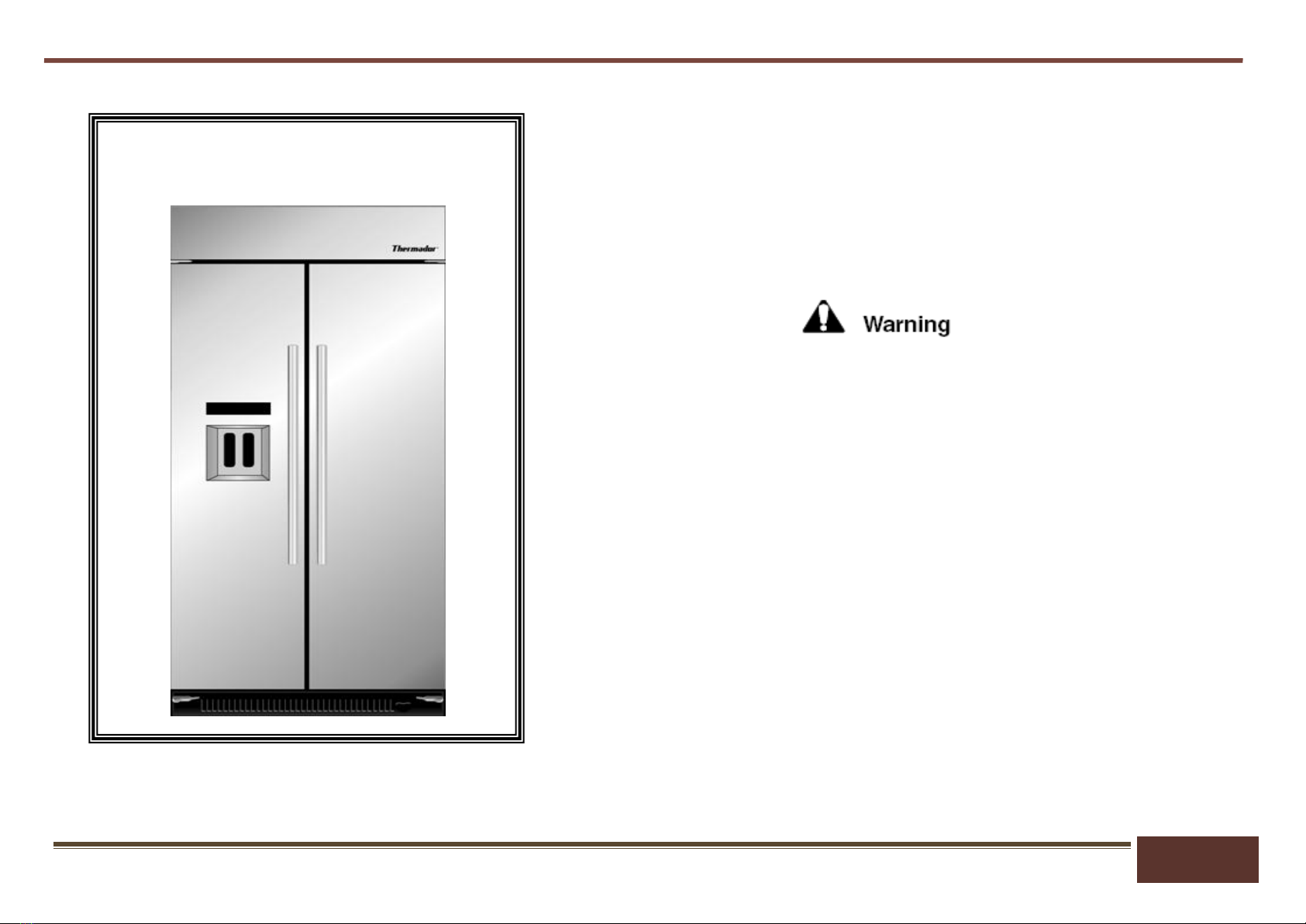
SERVICE MANUAL Thermador Built-In Refrigerator T42BD810NS, T42BD820NS, T42BR810NS, T42BR820NS, T48BD810NS, T48BD820NS, T48BR810NS, T48BR820NS
Copyright by BSH Home Appliances Corporation 1901 Main St ▪ Suite 600 ▪Irvine, CA 92614 58300000174337_ARA_EN_D 800 444-9091
This material is intended for the sole use of BSH authorized persons and may contain confidential and proprietary information. Any unauthorized review, use, copying, disclosure, or distribution in any format is prohibited.
Sealed System Procedure............................................................. 31
Before entering the Sealed System.............................................. 31
Conditions That Mimic a Sealed System Failure......................... 32
Icemaker Diagnostics.................................................................... 33
Icemaker Module Test Instructions.............................................. 34
Module Ohmmeter Checks............................................................ 35
Service and Disassembly Procedures ......................................... 36
Ingredient Care Center .................................................................. 37
COMPONENT ACCESS.......................................38
Compressor Component Compartment....................................... 38
Condenser Fan Motor & Door Switch Removal........................... 39
Door Switch Removal.................................................................... 40
Freezer Door Removal................................................................... 41
Freezer Door Removal - Cont’d .................................................... 42
Cavity Light Replacement............................................................. 43
Icemaker removal........................................................................... 44
Icemaker Removal - Cont’d ........................................................... 45
Icemaker Removal ......................................................................... 46
Ingredient Air Door Removal ........................................................ 47
Evaporator Cover Removal........................................................... 48
Defrost Control Component Access ............................................ 49
Evaporator Fan Removal............................................................... 50
Evaporator Fan Removal - Cont’d ................................................ 51
Defrost Heater Removal ................................................................ 52
Defrost Heater Removal ................................................................ 53
Defrost Heater Removal ................................................................ 54
Chilled Water Tank Removal......................................................... 55
Ice Dispenser Bucket Removal..................................................... 56
Auger Motor Removal.................................................................... 57
Auger Motor Removal.................................................................... 58
Ice Dispenser Bucket Disassembly.............................................. 61
Removing Front Panel & Dispenser Pad Access........................ 62
Removing Front Panel & Dispenser Pad Access - Cont’d.......... 63
Removing Front Panel & Dispenser Pad Access - Cont’d.......... 64
Removing Front Panel & Dispenser Pad Access - Cont’d.......... 65
Dispenser Display Removal.......................................................... 66
Ice Flapper Door Removal............................................................. 67
Water Inlet Removal....................................................................... 68
Water Filter Replacement.............................................................. 69
Water Filter Assembly Removal.................................................... 70
Water Fill Valve Removal............................................................... 71
Upper Cavity Light Bulb Replacement......................................... 72
Control Board Removal................................................................. 73
Control Board Removal –Cont’d.................................................. 74
Door Gasket Removal.................................................................... 75
TECHNICAL SPECIFICATIONS & WIRING
DIAGRAMS...........................................................76
Technical Information 42” & 48” Models ..................................... 76