BTR UTP modul System User manual

112003/2.000/01/B/899 035
Mounting instructions
Instructions d’installation
Montageanleitung
System
24x8 category 6 patch panel
panneau de brassage 24x8 catégorie 6
24x8 Cat.6 Patchfeld
Pin assignment according to ISO/IEC 11801, EN50173
Please note colour coding according to TIA/EIA-568A for the wiring.
Schéma de câblage selon ISO/IEC 11801, EN50173
Prière de respecter le code couleur selon TIA/EIA-568A pour le câblage.
Beschaltung nach ISO/IEC 11801, EN50173
Bitte beachten Sie die Farbkodierung für die Verdrahtung gemäß TIA/EIA-568A.
Pin assignment
Schéma de câblage
Beschaltungshinweise
Mechanical
features
Wire termination:
IDC by BTR:
wire 0.4 - 0.65 mm AWG 26 - 22
isolation 0.7 - 1.4 mm (1.6 mm)
AWG 26/7 bare stranded copper
wire with 7 strands
Reusable for AWG 22, AWG 23
and AWG 24 when using a wire
with the same or bigger cross
section.
Caractéristiques
mécaniques
Connexion des fils: bloc de
jonction autodénudant BTR-IDC:
fil 0,4 - 0,65 mm AWG 26 - 22
isolation 0,7 - 1,4 mm (1,6 mm)
AWG 26/7 fil de cuivre nu
à 7 brins
Réutilisation possible pour
AWG 22, AWG 23 et AWG 24 en
utilisant une section pareille
ou plus grande.
Mechanische
Eigenschaften
Adernanschluss:
Schneidklemme BTR-IDC:
Leiter 0,4 - 0,65 mm AWG 26 - 22
Isolation 0,7 - 1,4 mm (1,6 mm)
AWG 26/7 Litzenleiter mit
7-drähtiger CU-Litze blank
Wiederverwendbar für AWG 22,
AWG 23 und AWG 24 bei
Verwendung eines gleichen
oder größeren Querschnitts.
System

Cable preparation
Préparation d’un câble
Kabelkonfektion
Cable termination
Installation d’un câble
Kabelmontage SystemSystem
Remove about 25 mm (max. 30 mm) of the plastic
cover.
Enlever environ 25 mm (max. 30 mm) du revêtement
plastique.
Kunststoffmantel ca. 25 mm (max. 30 mm) abisolieren.
Separate the pairs of wire as to their coming out at
the cable end...
Séparer les paires de fils suivant leur position de
sortie au bout du câble...
Je nach Austritt des Kabelendes Adernpaare sepa-
rieren...
Insert the white/brown and white/orange pairs of
wires into the lower part of the loader...
Insérer les paires de fils blanc/marron et blanc/orange
dans la partie inférieure de la pièce d’installation...
Die Adernpaare weiß/braun und weiß/orange unten
in das Ladestück einführen...
...and place the blue/white and green/white pairs of
wire into the upper part.
...et placer les paires de fils bleu/blanc et vert/blanc
dans la partie supérieure.
...die Adernpaare blau/weiß und grün/weiß oben in
das Ladestück einlegen.
3b
... and cut them flush.
... et couper les nets.
...und die Kabeladern bündig abschneiden.
Wires can’t be cut really flush with an inappropriate
wire cutter. This will cause problems for the assem-
bling of the two housing parts.
Les fils ne se laissent pas couper bien nets avec un
coupe-câble inapproprié. Cela causera des problèmes
à l’assemblage des deux parties du boîtier.
Mit einem ungeeigneten Seitenschneider lassen sich
die Kabeladern nicht bündig abschneiden. Dies
führt zu Problemen beim späteren Zusammenfügen
der beiden Gehäuseteile.
...and arrange them as shown on the photo to
facilitate wire insertion to the module later.
...et les arranger comme sur la photo pour faciliter
ensuite l’insertion au module.
...und nach dem Bild anordnen, um die Adern später
leichter in das Modul einführen zu können.
brown/white
marron/blanc
braun/weiß
white/blue
blanc/bleu
weiß/blau
white/green
blanc/vert
weiß/grün
orange/white
orange/blanc
orange/weiß
Use a wire cutter of appropriate size to remove the
wire ends...
Utiliser un coupe-câble d’une taille approprié pour
enlever les bouts de fils dépassants...
Zum Entfernen der überstehenden Adern einen ge-
eigneten Seitenschneider verwenden...
2
A cable tie can be placed as strain relief (not included
to packing unit).
Un serre-câble peut être placé pour le soulagement
de traction (n’est pas inclus dans l’emballage).
Optional kann ein Kabelbinder zur Zugentlastung
angebracht werden (nicht im Lieferumfang enthalten).
3a1a
7 white blanc weiß
8 brown marron braun
3 white blanc weiß
6 orange orange orange
1b
4 blue bleu blau
5 white blanc weiß
2 green vert grün
1 white blanc weiß
white/brown
blanc/marron
weiß/braun
white/blue
blanc/bleu
weiß/blau
white/orange
blanc/orange
weiß/orange
white/green
blanc/vert
weiß/grün
Assemble the housing by placing the loader straight
on to the lower housing part.
Assembler le boîtier en posant la pièce d’installation
tout droit sur la partie inférieure du boîtier.
Beim Zusammenfügen der Gehäuseteile das Lade-
stück gerade auf das Gehäuseunterteil setzen.
4
max.
30 mm
white/brown
blanc/marron
weiß/braun
white/blue
blanc/bleu
weiß/blau
white/orange
blanc/orange
weiß/orange
white/green
blanc/vert
weiß/grün
A
A
B
B
brown/white
marron/blanc
braun/weiß
white/blue
blanc/bleu
weiß/blau
white/green
blanc/vert
weiß/grün
orange/white
orange/blanc
orange/weiß

Installation version B
Version d’installation B
Einbauvariante B System
Prepare and terminate the cable (see steps 1 to 4).
Préparer et raccorder le câble (voir pas 1 à 4).
Kabelkonfektion und Kabelmontage durchführen
(Schritte 1 bis 4).
Fit the module faceplate into the upper rim
of the module...
Accrocher la face du module au bord supérieur...
Modulaufnahme oben auf das Modul haken...
Take off the face plates of the empty module
openings (see “disassembling”) and slip the cable
from the rear through the mounting frame.
Enlever les couvertures vides (voir “démontage”)
et glisser le câble par derrière à travers le support du
panneau.
Leere Modulaufnahme lösen (siehe auch “Lösen der
Modulaufnahme”) und die Kabel von hinten durch
den Tragrahmen führen.
Then fit this unit into the underside of the
sockets in the mounting frame and click backwards
into place.
Accrocher cette unité ensuite au bord inférieur de
l’ouverture du panneau et l’enclencher en arrière.
Anschließend diese Einheit an der Unterseite der
Steckplätze am Tragrahmen einhaken und nach hin-
ten einrasten.
... and click it downwards into place.
... et l’enclencher vers le bas.
... und nach unten einrasten.
6a
7
6b
Mounting preparation
Préparation du montage
Montagevorbereitung
Insert the cables into the designated clamping
fixture.
Insérer les câbles dans les attaches prévues.
Kabel in die entsprechende Halterung einlegen.
Fit the assembled module into the upper rim of the
module socket from the rear and click it downwards
into place.
Accrocher le module assemblé par l’arrière au bord
supérieur de l’ouverture et l’enclencher vers le bas.
Das fertig angeschlossene Modul von hinten am
oberen Teil der Modulaufnahme einhaken und nach
unten einrasten.
Installation version A
Version d’installation A
Einbauvariante A System
7
6
bottom
face inférieure
Unterseite
top
face supérieure
Oberseite
If the plier is applied too far back the loader may get
out of place and dammage the ID connectors inside
the module.
Une pince appliquée trop à l’arrière peut faire glisser
la pièce d’installation et endommager les blocs de
jonction à couteau à l’interérieur du module.
Wird die Zange zu weit hinten angesetzt, kann es
passieren, dass das Ladestück verrutscht und die
Schneidklemmen im Inneren des Moduls beschädigt
werden.
5
Place a plier in the middle of the module and press
until the housing is closed.
Appliquer une pince au milieu du module et serrer
jusqu’à ce que le boîtier soit fermé.
Eine Zange in der Modulmitte ansetzen und das
Modul zusammendrücken bis das Gehäuse ge-
schlossen ist.
Cable termination
Installation d’un câble
Kabelmontage System

Important notes
Indications importantes
Wichtige Hinweise System
Notes for the user and installer
Our termination systems and patch products for the generic cabling meet the currently valid
standards EN 50173-1:2002 and IEC 60603-7.
The user or installer has to check and take care to use solely patch and termination cables that
meet the EN-/IEC standards when completing the installation. If necessary ask your supplier to
certify that the installed cables and plugs meet the standards. The use of products that do not
comply with the above-mentioned standards may cause malfunctions and affect performance.
Indications pour utilisateurs et installateurs
Nos systèmes de raccordement et produits de distribution pour le câblage générique sont con-
formes aux normes en vigueur EN 50173-1:2002 et IEC 60603-7.
Il est nécessaire que l’utilisateur ou l’entreprise d’installation vérifient et tiennent compte
d’employer uniquement les câbles de distribution et de raccordement qui répondent aux
normes EN-/IEC. Il est conseillé de se faire certifier cette conformité aux normes par le fournis-
seur des câbles et fiches utilisés. L’utilisation de produits qui ne sont pas conformes aux normes
ci-dessus peut causer des perturbations des fonctions ou de la performance.
Hinweis für Verwender und Monteure
Unsere Anschlusssysteme und Verteilerprodukte für die strukturierte Gebäudeverkabelung
entsprechen den gültigen Normen EN 50173-1:2002 und IEC 60603-7.
Bei Komplettierung der Anschlüsse muss der Verwender/Montagebetrieb prüfen und beachten,
dass nur Patch- und Anschlusskabel, die die EN-/IEC-Normen erfüllen, verwendet werden.
Lassen Sie sich ggf. vom Lieferanten den Nachweis geben, dass die eingesetzten Kabel und
Stecker der Norm entsprechen. Die Verwendung von Produkten, die nicht den vorstehenden
Normen entsprechen, können Funktions- und Leistungsstörungen zur Folge haben.
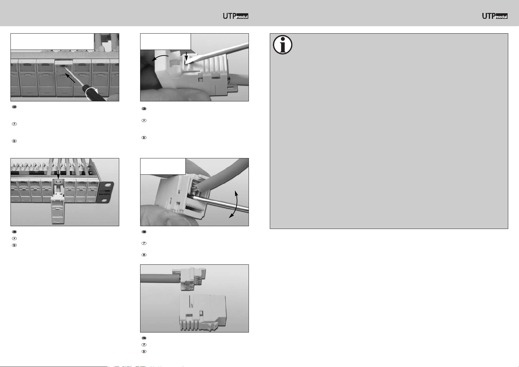
Carefully lever out the loader from the back of the
module...
Décrocher la pièce d’installation à l’arrière avec
précaution...
Das Ladestück auf der Rückseite des Moduls vor-
sichtig aushebeln...
...and separate the two parts of the housing.
...et détacher les deux parties du boîtier.
...und beide Gehäuseteile voneinander trennen.
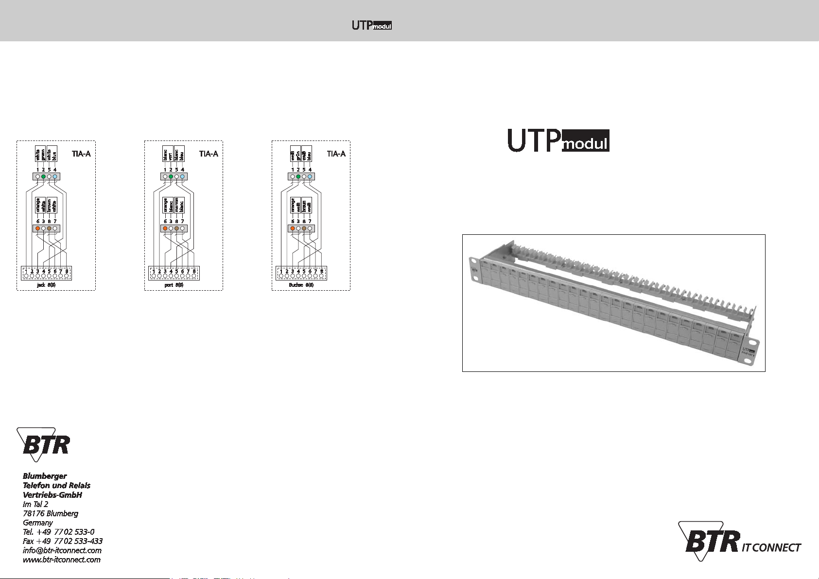
System
Disassembling individual components
Démontage des différents éléments
Demontage der einzelnen Komponenten
Pull the unit out of the frame.
Retirer l’unité du support.
Einheit aus dem Tragrahmen herausziehen.
Press the clamping strip at the bottom of the module
down with a screw driver and remove the module unit.
Appuyer avec un tournevis sur la plaquette de
verrouillage, côté inférieure du module et enlever
l’unité de module.
Klemmleiste auf der Unterseite des Moduls mittels
Schraubendreher eindrücken und Modulaufnahme
abnehmen.
To release a module unit open the label window,
insert a flat bladed screw driver into the upper
opening and twist.
Pour déverrouiller une unité de module ouvrir la
fenêtre à étiquette, ensuite introduire un tournevis
plat dans l’ouverture en haut et le tourner.
Modulaufnahme entriegeln, hierzu Sichtfenster öff-
nen und einen flachen Schraubendreher in die obere
Öffnung schieben und drehen.
Unbolt a module faceplate
Décrocher une couverture de module
Lösen der Modulaufnahme
Removing a module
Décrocher un module
Lösen des Moduls
Opening a module
Ouvrir le module
Öffnen des Moduls
Other BTR Network Cables manuals