Buchi B-180 User manual

1
BÜCHI Vacuum System B-180
Version B (20 pages) Order code
B-180 Instructions 96653
Contents
Contents
1 Scope of the delivery 2
2 Safety 3
3 Function 6
4 Putting into operation 7
5 Operation 12
6 Maintenance 15
7 Taking out of operation 18
8 Replacement parts and accessories 19
9 Appendix 20
Read these instructions carefully before you use the Büchi
Vacuum System B-180. Keep these instructions in a safe place
close to the unit for quick reference whenever required.
Chapter 2 contains important notes concerning safety. It is
imperative to read these notes in order to operate the unit safely.
!
Subject to change without prior announcement. No part of these
instructions may be reproduced in any form or be processed,
duplicated or distributed by electronic or optical means without
the written permission of Büchi Labortechnik AG.
All rights reserved.
© Büchi Labortechnik AG, 1995

2
BÜCHI Vacuum System B-180
1 Scope of delivery
1 Scope of delivery
Figure 1: Vacuum System B-180
Designation
Versions of the apparatus: Order Code
Büchi Vacuum System B-180 cpl. 120 V 36611
Büchi Vacuum System B-180 cpl. 230 V 36605
Parts enclosed:
2 cable ties
(for use see Section 4.4,Tube connections) 14295
2 x 2m Vacuum hose 17622
6-KT Allen wrench SW3
(for Vacuum Controller extention) 00610
Mains cable PNE
Type CH 10010
Type Schuko 10016
Type GB 17835
Type AUS 17836
Type USA 10020
Instructions
German 96652
English 96653
French 96654
Italian 96655
Spanish 96656
2 Control cables for Rotavapors R-134/
R-144 or Vacuum Controller B-168 31238
Table 1: Scope of delivery

3
BÜCHI Vacuum System B-180 2 Safety
2 Safety
The B-180 is built in conformance with the state of engineering
and the recognized rules of safety.
Provided it is used as intended, the unit will not be a source of
any risks or hazards.
2.1 Symbols
Stop
Information about hazards which can lead to serious material
damage or cause serious or potentially fatal injury.
Warning
Information about hazards which can be harmful to your health
and lead to material damage.
Please note
Information about technical requirements. Non-observance can
lead to malfunctions, inefficiency and lost production.
2.2 Requirements to be met by the customer
The B-180 must only be operated by trained laboratory staff
and other persons who have the necessary training or profes-
sional experience to recognize the hazards that can arise when
using the system. Personnel without such training or persons
currently undergoing a course of training require thorough in-
struction in the use of the system. These instructions should
be read by all personnel prior to the use of the B-180.
If solvents of unknown composition are to be processed, it is
the operator’s responsibility to consult a specialist office for
information about the hazards which may be entailed in such
processing.
2.3 Proper use
The System B-180 is designed and constructed as a laboratory
apparatus. Its specified use is the evacuation of two laboratory
apparatuses to a vacuum of <15 mbar. This is done with a
PTFE diaphragm pump regulated by two Vacuum Controllers.
The pump is 100% oil-free. The bearings are sealed and self-
lubricating and must therefore not be greased.
Applications include the evacuation of:
• Distillation apparatuses, especially rotary evaporators
• Vacuum filtration systems
• Vacuum drying ovens
!

4
BÜCHI Vacuum System B-1802 Safety
2.4 Improper use
These laboratory apparatuses are not suitable for use in
potentially explosive areas.
The apparatus is only suitable for pumping air or vapors and
not liquids or solid particles, which would destroy the pump or
reduce its performance.
Any use other than that mentioned above, or any application
which does not comply with the technical specifications, is
regarded as an incorrect application. The operator bears sole
responsibility for any damage attributable to such use.
2.5 General hazards
Hazards arise generally from:
• Glass parts which are not suitable for use under vacuum
• Solvents which can react with each other if they come
together in the pump or in the secondary condenser
• Sources of ignition in the immediate vicinity of the exhaust
line
• Flammable gases or solvent vapors in the immediate vicinity
of the exhaust hose
• Damaged glassware
• Kinked tubing
2.6 Safety measures
• Personal safety items such as goggles and a laboratory
coat must be worn.
• These instructions are to be considered a part of the
B-180. They must always be kept at the point of use so
that operating personnel can consult them at any time.
This also applies to copies in other languages, which can
be ordered separately (see Chapter 1, Scope of delivery).
• The customer shall notify the manufacturer immediately of
any incidents involving safety aspects during the use of the
appliance.
• Regional and local laws and regulations must be observed.
• Modifications are only permitted after consulting with the
manufacturer and obtaining his written consent.
!

5
BÜCHI Vacuum System B-180 2 Safety
2.7 Safety elements
Electronics
• The apparatus is fitted with fuses
Operation
• At an absolute pressure of more than 1400 mbar, the
built-in ventilation valve opens automatically.
Glassware
• Use of high-quality inert borosilicate glass 3.3
• Threaded hose connections to prevent glass breakage
Safetyscreen
The safety screen protects the operator from any broken glass
and implosions.

6
BÜCHI Vacuum System B-180
3 Function
3 Function
The B-180 Vacuum System produces and regulates two in-
dependent vacuums and keeps them constant: if there is a
loss of vacuum in the evacuated apparatus, the vacuum pump
directly switches on and off in order to automatically bring the
vacuum back to the chosen nominal pressure.
The vacuum, which is chosen specifically for the solvent, affords
almost 100% condensation in the condenser of the distillation
apparatus, thereby massively reducing the solvent emissions.
Any aspirated solvent vapors found in the built-in high-efficiency
condenser are condensed out downstream of the pump.
A cooling water valve also enables the cooling water throughput
to be controlled during distillation, saving up water consumption
by up to 95%.
To choose the optimal distillation conditions, see Section 5.4,
Application information.
B-180
Main switch
2 x separator
PTFE diaphragm pump
Secondary condenser
Receiving flask 450 ml
Figure 2: Functional elements

7
BÜCHI Vacuum System B-180 4 Putting into operation
4 Putting into operation
4.1 Unpacking
Cardboard box
Apparatus fixation
Apparatus
The original packaging is to be kept for storage or possible
transport at a later date.
4.2 Location
It's not allowed to use the apparatus in explosion-proof rooms.
The apparatus must stand on a flat, horizontal, stable surface.
Figure 3: Packaging
!

8
BÜCHI Vacuum System B-1804 Putting into operation
Mains voltage!
Mains socket
Fuse
Mains connector for Vacuum Controller 1, R-134 / R-144
Mains connector for Vacuum Controller 2, R-134 / R-144
Socket for a Büchi Rotavapor (only 230 V-Version)
24 V control voltage
Connector for Vacuum Controller 1, socket V
Connector for Vacuum Controller 2, socket V
Socket for an external cooling water valve
Connector for the valve unit
Tubes
Cooling water inlet
Cooling water outlet
Exhaust
Vacuum socket for apparatus 1
(e.g. Rotavapor, vacuum drying oven)
Vacuum socket for apparatus 2
(e.g. Rotavapor, vacuum drying oven)
4.3 Installation
Figure 4: Installation with 2 B-720 Vacuum Controllers

9
BÜCHI Vacuum System B-180 4 Putting into operation
The adhesive labels supplied are for labelling the controller, rotary
evaporator and separator, making it easy to identify which rotary
evaporator is connected to which Vacuum Controller via which
separator. Accordingly, the corresponding components are to
be given e.g. the same number.
The B-180 can be controlled externally by the following
apparatuses:
• Vacuum Controller B-720
• Vacuum Controller B-168
• Rotavapor R-134
• Rotavapor R-144
To control the apparatus externally, the control cable supplied (order
code 36493) has to be connected to the external controller (B-
720, B-168, R-134 or R-144), the connection being made between
V1 on the B-180 and V on the controller. The control cable supplied
(order code 31238) has to be used if the external Vacuum Controller
is not a B-720.
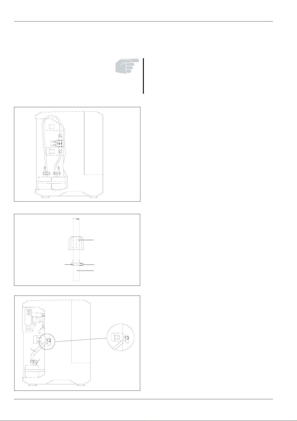
4.4 Tube connections
• The apparatus must never be operated without an exhaust tube.
• The exhaust tube must not point towards hot objects or objects
which produce sparks (Danger: flammable solvent vapors).
Whenever possible, the exhaust tube should be led into a hood
to ensure the solvent vapors do not come into the room.
• Care must be taken to ensure that no tubes are pinched (kinks,
apparatus standing on tube, etc.)
• Brittle tubes must be changed.
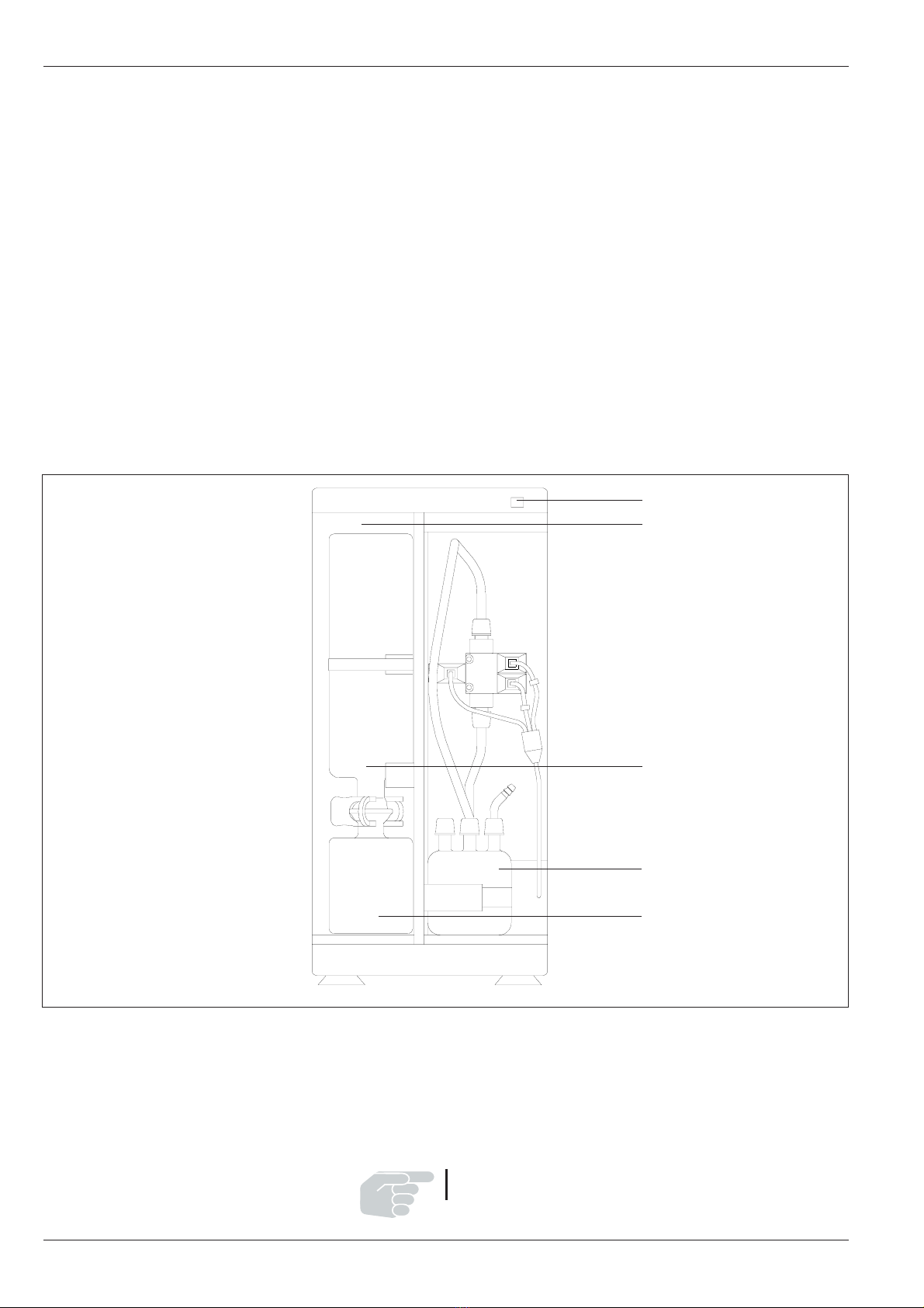
Cooling water:
Plug the cooling water valve into the socket . Let the cooling
water run through the condenser of the B-180 ( = inlet,
= outlet). The same cooling water can then be fed into the first
Rotavapor . If the cooling water is still cold enough, it can also
be used for a second Rotavapor . If the cooling water has
become too warm after the first Rotavapor, the second Rotavapor
must be cooled via a separate cooling water connector. Finally,
the cooling water is fed into the discharge .
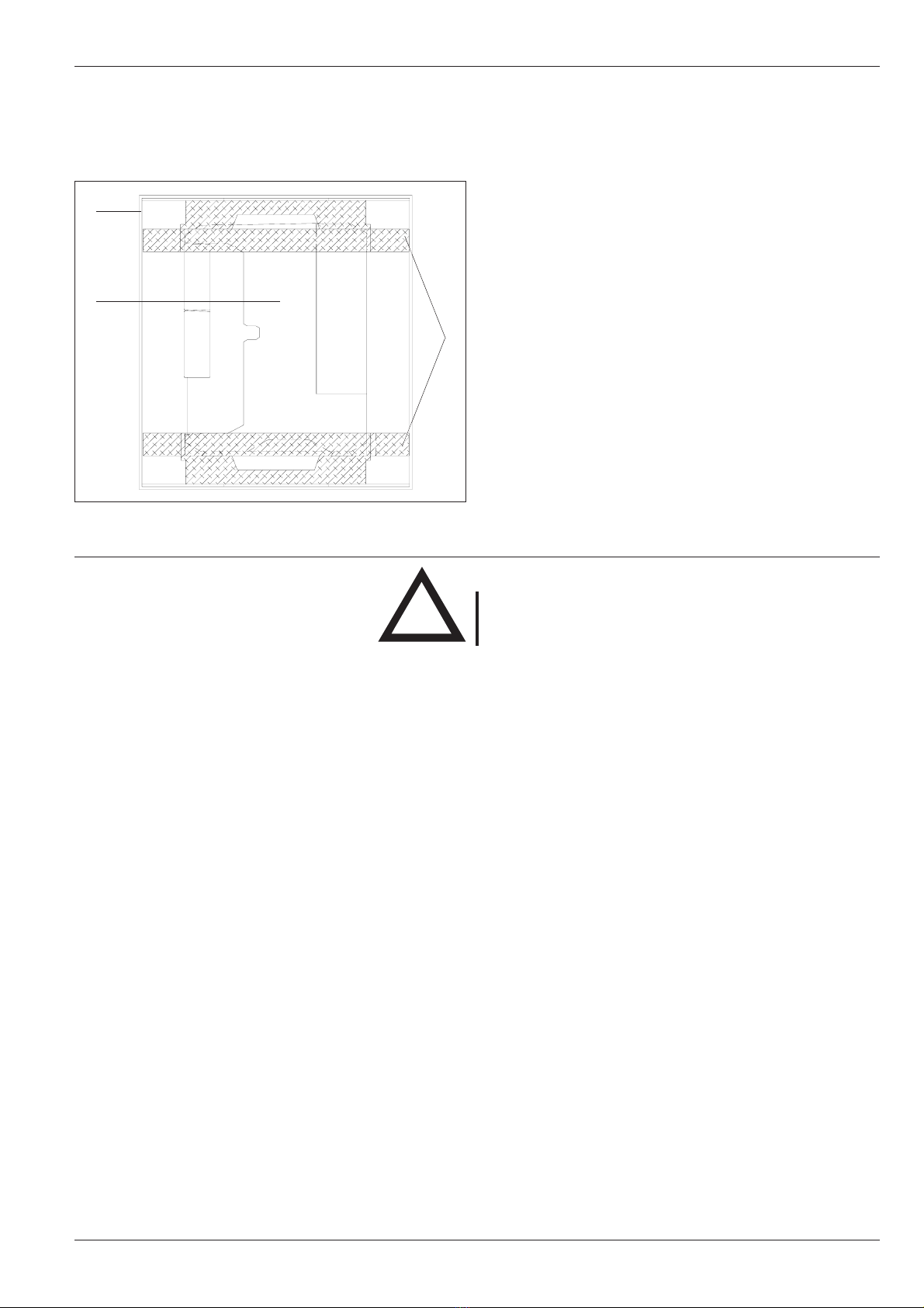
The cooling water flow must be reduced to 30-40 l/h (Cooling
water valve, needle valve).
!
Figure 5: Cooling water tubing

10
BÜCHI Vacuum System B-180
Figure 6: PTFE tubes in the apparatus
4 Inbetriebnahme
If both Rotavapors are cooled with the same cooling water, it
must first be passed through the Rotavapor in which the lower-
boiling solvent is being distilled.
For safety reasons, the tubes should be secured with commercially
available tube clips or cable ties. The tubes in the apparatus have
already been secured at the factory.
PTFE-tubes:
• The PTFE tubes are to be screwed on as shown in the
opposite diagram.
• Care must be taken to ensure the tubes and seals are never
kinked.
• To attach the PTFE tubes to the Vacuum Controller or remove
them, it is best to unscrew the controllers and fix/remove the
tubes away from the apparatus.
Screw cap GL14
PTFE-sealing
Rubber-sealing
PTFE-hose
Glass thread GL-14
Vacuum hose
• The vacuum hoses used must have an internal diameter of 6
mm.
• The vacuum tubes should all be kept as short as possible.
• It is not necessary to secure the tubes to the tube connec-
tors.
• The vacuum hose can be fastened with one of the cable ties
supplied, as shown in the opposite diagram.
• The hose can leave the housing ether trough the opening at
the side or by passing the cable channel to the backside.
Figure 8: Fixing of vacuum hose
Figure 7: PTFE screw coupling

11
BÜCHI Vacuum System B-180
4.5 Ventilation with inert gas
The Vacuum Controllers are fitted with a tube connector on the
ventilation valve. This connector can be used for ventilation with
inert gas.
Do not ventilate with a overpressure greater than 400 mbar.
Make sure that the apparatus to be evacuated can also
withstand a overpressure of 400 mbar.
4.6 Electrical connections
Controller 1 or R-134 / R-144
Controller 2 or R-134 / R-144
Valve unit in the apparatus
Cooling water valve
Mains cable
Büchi Rotavapor (only at 230 V)
Check that the voltage at the power socket corresponds to
the voltage indicated on the identification plate.
The B-180 Vacuum System should always be connected to a
grounded power socket. External couplings and extension
cables must carry a ground wire. Any interruption of the ground
wire is forbidden because it removes the protective function in
the event of electrical defects.
!
Figure 9: Cable diagram
4 Putting into operation

12
BÜCHI Vacuum System B-180
5 Operation
5.1 Application information
Choosing the distillation conditions
To achieve optimal distillation conditions with rotary evaporators,
the energy fed into the distillation from the heating bath has to
be dissipated via the condenser. To ensure this, it is recommen-
ded to work according to the following rule of thumb:
T
2
(min. 20½ C)
T
1
(20½C–30½ C)
How are these conditions achieved?
• Adjust bath temperature to 60°C
• Adjust cooling water, temperature not to exceed 20°C
• Run distillation cooling water through the condenser at
about 40-50 l/h
• The working vacuum is to be chosen so that the solvent
boils at 40°C. The Solvent Table (next page) gives the cor-
responding pressure.
Advantages of using a 60°C bath temperature:
• The evaporating flask can be changed without the risk of
scalding
• The rate of evaporation of water from the heating bath is
not very high (energy loss)
• The heating bath energy is utilized efficiently
Optimization of the distillation:
Depending on the solvent to be distilled, the distillation confi-
gurations may need to be re-adjusted. Before re-optimization,
however, the heating bath must have reached 60°C.
The following applies:
Condensation of the solvent is supposed to take
place over
2/3
to
3/4
of the available cooling surface.
There are basically two possible ways of optimizing the distillation:
1. Slowly lower pressure further
Bath temperature must be 60 °C!
(Boiling point is lowered, T
1
is increased, thereby increasing
the distillation capacity)
or
2. Raise bath temperature
(T
1
is increased, thereby increasing the distillation capacity)
By raising the bath temperature, however, not all the additional
energy is transferred to the distillation; more is lost to be the
surroundings by radiation. This arises due to the increased
difference between the temperature of the bath and the
surroundings.
If it is found impossible to work according to this rule, it is
important for the difference between the vapour temperature
and cooling water temperature to be at least 20°C.
Cooling Water Vapour Bath
max 20°C 40°C 60°C
Figure 11: Condensation range
Figure 10: „20-40-60“
▲
▼
2
/
3
5 Operation

13
BÜCHI Vacuum System B-180 5 Operation
Solvent Formula Molary weight Energie of Boiling point in °C Tightness Vacuum in mbar
in g/mol evaporation in J/g at 1013 mbar in g/cm
3
for boiling at 40 ºC
Acetic acid C
2
H
4
O
2
60.0 695 118 1.049 44
Aceton C
3
H
6
O 58.1 553 56 0.790 556
N-Amylalcohol, n-Pentanol C
5
H
12
O 88.1 595 37 0.814 11
Benzene C
6
H
6
78.1 548 80 0.877 236
n-Butanol, tert. Butanol C
4
H
10
O 74.1 620 118 0.810 25
2-Methyl-2-Propanol C
4
H
10
O 74.1 590 82 0.789 130
Carbontetrachloride, tetra Chloromethane CCI
4
153.8 226 77 1.594 271
Chlorobenzene C
6
H
5
CI 112.6 377 132 1.106 36
Chloroform CHCI
3
119.4 264 62 1.483 474
Cyclohexane C
6
H
12
84.0 389 81 0.779 235
Diethyl ether C
4
H
10
O 74.0 389 35 0.714 850*
1,2,-Dichloroethane C
2
H
4
CI
2
99.0 335 84 1.235 210
1,2,-Dichloroethylene (cis) C
2
H
2
CI
2
97.0 322 60 1.284 479
1,2,-Dichloroethylene (trans) C
2
H
2
CI
2
97.0 314 48 1.257 751
Di isopropyl ether C
6
H
14
O 102.0 318 68 0.724 375
Dioxane C
4
H
8
O
2
88.1 406 101 1.034 107
DMF (Dimethylformamide) C
3
H
7
NO 73.1 153 0.949 11
Ethanol C
2
H
6
O 46.0 879 79 0.789 175
Ethyl acetat C
4
H
8
O
2
88.1 394 77 0.900 240
Heptane C
7
H
16
100.2 373 98 0.684 120
Hexane C
6
H
14
86.2 368 69 0.660 335
Isopropyl alcohol C
3
H
8
O 60.1 699 82 0.786 137
Isoamyl alcohol, 3-Methyl-1-Butanol C
5
H
12
O 88.1 595 129 0.809 14
Methyl ethyl ketone C
4
H
8
O 72.1 473 80 0.805 243
Methanol CH
4
O 32.0 1227 65 0.791 337
Methylenechloride, Dichloromethane CH
2
CI
2
84.9 373 40 1.327 850*
Pentane C
5
H
12
72.1 381 36 0.626 850*
n-Propyl alcohol C
3
H
8
O 60.1 787 97 0.804 67
Pentachlorethane C
2
HCI
5
202.3 201 162 1.680 13
1,1,2,2,-Tetrachloroethane C
2
H
2
CI
4
167.9 247 146 1.595 35
1,1,1,-Trichloroethane C
2
H
3
CI
3
133.4 251 74 1.339 300
Tetrachloroethylene C
2
CI
4
165.8 234 121 1.623 53
THF (Tetrahydrofurane) C
4
H
8
O 72.1 67 0.889 357
Toluene C
7
H
8
92.2 427 111 0.867 77
Trichloroethylene C
2
HCI
3
131.3 264 87 1.464 183
Water H
2
O 18.0 2261 100 1.000 72
Xylene (Isomers mixture) C
8
H
10
106.2 389 25
(o) 144 0.880
(m) 139 0.864
(p) 138 0.861
Table 2: Solvents * only possible when cooling water is 20°C
Solvents

14
BÜCHI Vacuum System B-180
5.5 Troubleshooting
Malfunction Possible cause Remedy
Frequent switching of the value System is leaking Check all sealing points
and pump (vacuum tubing and their connections)
Chosen hysteresis too small Choose larger hysteresis (bei
(if end vacuum greater than 700 mbar,
set to automatic hysteresis)
Valve does not switch Valve does no close Valve coil dirty
Valve cable not plugged in (socket „P“
at the back of the apparatus)
No vacuum Tube connections incorrect See Section 4.4, Tube connections
Cable connections incorrect See Section 4.6, Electrical connections
Vacuum is not obtained Solvent residues in the system Empty "Woulff" bottle and re-assemble dry
Start pump with vacuum tube open. Run
for 1-2 min. to blow out vapour residues
Dirty valve plates in the pump Clean or replace valve plates
Shaped diaphragm defective Change shaped diaphragm
Table 3: Troubleshooting
5 Operation

15
BÜCHI Vacuum System B-180
All instructions aimed at keeping the System B-180 in working
order are to be observed. This also includes periodic cleaning
and checking for any damage.
6.1 Cleaning
The glass parts are rinsed with commercially available cleaning
agents (e.g. mild soap solution). Dirt mineral deposits and residues
in the condenser coils (e.g. algae) should be removed with suitable
cleaning agents (allow glassware to soak for a period of time, if
necessary). After cleaning and thoroughly drying, each glass part
is to be examined visually for splinters or cracks. Because the
separators are under vacuum during operation, this visual check
is to be carried out conscientiously!
The housing and the cover are to be cleaned with a damp cloth:
Do not use solvents! The outer housing should also be checked
visually for defects (controls, plugs).
Tubing connections are also to be checked visually: cracked or
brittle tubes are to be replaced with appropriate new tubes.
6.2 Changing the shaped diaphragm and valves
Under normal use, the shaped diaphragms and valve plates must
be changed from time to time.
When is this necessary?
• When a marked loss of efficiency is noted (evacuation rate).
• The ultimate rated vacuum clearly can not be reached
(max. 60 mbar).
The shaped diaphragms and valve plates should be changed in
both pump heads at the same time.
1. Warning: Pull out mains plug before opening the apparatus!
2. Loosen the 4 hexagon socket screws on the cover and
remove the cover.
3. Loosen the tubing connections on the heads.
Make a vertical pencil line to mark the position of the housing
with intermediate ring , distance plate , head cover and
pressure plate .
Changing the shaped diaphragm
• Loosen the 6 countersunk bolts .
• Lift off the top part of the head.
• Remove the shaped diaphragm by hand, turning counter-
clockwise, and take off the spacer disks .
• Replace the spacer disks with new disks.
• Screw on a new shaped diaphragm clockwise and tighten
by hand.
• Replace the top part of the head matching the pencil mark.
• Tighten the 6 countersunk bolts via the recessed heads.
6 Maintenance
5
▲
▼
Figure 12: Changing the shaped diaphragm
6 Maintenance

16
BÜCHI Vacuum System B-180
Figure 13: Changing fuses
Changing the valve plates and sealing rings
• Loosen the 6 countersunk bolts .
• Loosen the 2 cylinder screws with the cup springs .
• Take off the pressure plate and the head cover .
• Take off the valve plates and sealing rings and replace
with new ones.
• Replace the head cover and pressure plate according
to the pencil mark.
• Tighten the 6 countersunk bolts via the recessed heads.
• Insert the cup springs as shown in the diagram and
only gently tighten the cylinder screws .
6.3 Changing the fuse
The apparatus is fitted with a safety fuse. This fuse is built into the
main power supply socket found on the back of the apparatus.
Before changing the fuses, always pull out the mains plug first.
First push up the clip on the fuse holder and then pull out
the fuse holder. After changing the fuse, push the fuse holder
back in.
If the replacement fuse immediately burns out again, please call
appropriate Büchi Customer Service.
Fuses:
Vacuum System B-180: 120 V 4 AT
Vacuum System B-180: 230 V 2 AT
6.4 Customer Service
Interventions on or in the apparatus may only be carried out by
authorized service engineers, i.e. persons with a sound profes-
sional technical training and knowledge of the dangers which
arise from failure to observe safety procedures.
A specific service manual for the apparatus, which can only be
obtained by authorized personnel, is available from Büchi Cus-
tomer Service.
The addresses of the official Büchi Customer Service Depart-
ments are given on the back cover of these operating instructions.
If you are experiencing faults or have any technical questions or
application problems, please consult these service departments.
Büchi’s Customer Service offers the following services to its
customers:
• Spare parts service (Please refer to the order codes printed
in the operating instructions)
• Repair service
• Maintenance service
• Technical advice. Please consult the Büchi agent in your
country, either by telephone or in writing.
6 Maintenance

17
BÜCHI Vacuum System B-180
The mains cable must be unplugged before the apparatus is
transported.
Hazardous substances must be removed and the apparatus
must be cleaned thoroughly. This avoids any risk of persons
being harmed by contact with hazardous substances.
7.1 Storage/Transport
The apparatus must be stored in the original packaging and in a
dry place. It must also be transported in the original packaging.
7.2 Disposal
So that the apparatus can be disposed of with minimum harm
to the environment, Section 9.2, Materials used, contains a list
of the most important parts. This ensures that the parts can be
separately recycled. Electronic parts are to be disposed of in
compliance with the regional and local laws and regulations.
7 Taking out of operation
7 Ausserbetriebnahme

18
BÜCHI Vacuum System B-180
8
Replacement parts and accessories
27900
36622
36621
32885
27854
36107
36597
36613
36493
8 Replacement parts and accessories
27774
36477
03275
27549
27548
28667
Figure 14: Replacement parts
Figure 15: Replacement parts (pump head)
36468
Only Büchi original accessories guarantee the Büchi apparatus will
be safe to use and in working order. Spare parts and accessories
other than Büchi’s may only be used with the manufacturer’s
permission.
For the purpose of assembly or dismantling, the spare parts ca-
talog may only be used in conjunction with the corresponding
Sections 5 and 7 of the operating instructions. Perusal by and
disclosure to third parties, and manufacture on the basis of this
handbook, are forbidden. Büchi AG retains the copyright.
Replacement parts
Clamp for spherical ground-glass joint 03275
Cooling water tube, silicone 04133
Exhaust tube, silicone 04134
10 fuses 2 AT for 230V 19660
10 fuses 6,3 AT for 120V 22561
Shaped diaphragm 27548
Valve plate 27549
High-efficiency secondary condenser 27774
Tube seal cpl. 27854
PTFE tube 27900
Sealing ring 28667
Tube connector GL-14, bent, cpl. 32885
Woulff' bottle 36107
Inserted disk for externe control use 36466
Cover 36468
Receiving flask B-180 36477
Valve unit B-180 cpl. 36597
Control cable B-720 36493
Control cable B-168 / R-134 / R-144 31238
PTFE tube, ben 36613
Service kit
(2 x 27548 / 2 x 27549 / 2 x 28667) 37028
Accessories
Cooling water valve 31356
Vacuum tube 17622
Nyflex hose 14 x 8
(Alternative to the vacuum hose 17622) 04113
Vacuum Controller 230 V 36621
Vacuum Controller 120 V 36622
Control cable B-720 / R-153 31233
Cooling water valve to R-153 27380
Table 4: Replacement parts

19
BÜCHI Vacuum System B-180
9 Appendix
9.1 Technical Data
Dimensions (W x H x D) 24 x 51 x 40 cm
Weight 21 kg
Mains supply 230 V / 50–60 Hz
120 V / 50 –60 Hz
Voltage tolerance –15% . . . +10%
Power consumption 200 W
A.C. power at the socket for Rotavapor 230 V max. 1400 W
120 V max. 700 W
Ambient temperature 5 –40°C
Noise level ~ 50 dBA
Attainable vacuum 울15 mbar
Vacuumtightness typically 욷2 mbar per min.
Table 5: Technical data
9.2 Materials used
Part Material Material code
Housing, cover Rigid polyurethane foam PUR
Tubes Teflon PTFE
Silicone SI
Cover disk Plexiglass PMMA
Cabel Polyurethane PUR
Valve body Crastin PETP
Media-contacting materials: Glass, PTFE, PETP
Table 6: Materials used
9 Appendix

20
BÜCHI Vacuum System B-180
9 Appendix
We
Büchi Labortechnik AG
Postfach, CH-9230 Flawil
Switzerland
declare under our sole responsibility that the product:
BÜCHI Vacuum System B-180
to which this declaration relates is in conformity with the following standards:
EN 61010-1:1993 (~ IEC 1010-1, VDE 0411-1)
Safety requirements for electrical equipment for mesurement, control an laboratory use: General requirements
EN 55011:1991/B (~ VDE 0875/B, VDE 0871/B)
Limits and methods of measurement of radio disturbance characteristics of industrial, scientific and medical
radiofrequency equipment
following the provisions of EU-Directive:
73/23/EEC
89/336/EEC
Flawil, 1. Juni 1995
D. Simmler
Quality management
Büchi Labortechnik AG
9.3 Declaration of conformance
Table of contents