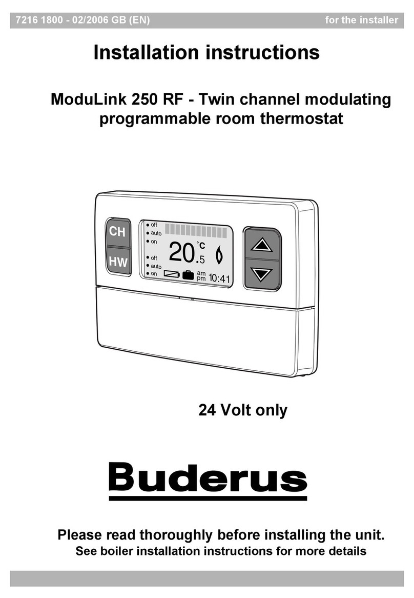
Buderus RT20 RF Installation instructions

Table of contents
RT20 RF Room Thermostat – 6721844608 (2022/03)
2
Table of contents 1 Explanation of symbols and safety
instructions
1.1 Explanation of symbols
Warnings
In warnings, signal words at the beginning of a warning are used
to indicate the type and seriousness of the ensuing risk if
measures for minimizing danger are not taken.
The following signal words are defined and can be used in this
document:
DANGER
DANGER indicates that severe or life-threatening personal
injury will occur.
WARNING
WARNING indicates that severe to life-threatening personal
injury may occur.
CAUTION
CAUTION indicates that minor to medium personal injury may
occur.
NOTICE
NOTICE indicates that material damage may occur.
Important information
The info symbol indicates important information where there is
no risk to people or property.
Additional symbols
Table 1
1 Explanation of symbols and safety instructions . . . . . .2
1.1 Explanation of symbols . . . . . . . . . . . . . . . . . . . . . . .2
1.2 General safety instructions . . . . . . . . . . . . . . . . . . . .3
2 Product Information . . . . . . . . . . . . . . . . . . . . . . . . . . . ..3
2.1 Scope of delivery . . . . . . . . . . . . . . . . . . . . . . . . . . . .3
2.2 About the appliance. . . . . . . . . . . . . . . . . . . . . . . . . .3
2.2.1 Intended use . . . . . . . . . . . . . . . . . . . . . . . . . . . . . . .3
2.2.2 Functions and features . . . . . . . . . . . . . . . . . . . . . . .4
2.3 Specifications . . . . . . . . . . . . . . . . . . . . . . . . . . . . . .4
2.4 Simplified EU Declaration of Conformity
regarding radio equipment . . . . . . . . . . . . . . . . . . . .5
2.5 Product data on energy consumption - EU
Regulations. . . . . . . . . . . . . . . . . . . . . . . . . . . . . . . . .5
2.6 Product data on energy consumption - ErP
Directive . . . . . . . . . . . . . . . . . . . . . . . . . . . . . . . . . . .5
3 Installation . . . . . . . . . . . . . . . . . . . .. . . . . . . . . . . . . . . . .5
3.1 Installation location . . . . . . . . . . . . . . . . . . . . . . . . . .5
3.2 Electrical connection. . . . . . . . . . . . . . . . . . . . . . . . .6
3.3 Mounting. . . . . . . . . . . . . . . . . . . . . . . . . . . . . . . . . . .6
3.4 Parameters. . . . . . . . . . . . . . . . . . . . . . . . . . . . . . . . .8
4 Operation . . . . . . . . . . . . . . . . . . . . .. . . . . . . . . . . . . . . . .8
5 Maintenance. . . . . . . . . . . . . . . . . . .. . . . . . . . . . . . . . . . .9
6 Troubleshooting. . .. . . . . . . . . . . . . . . .. . . . . . . . . . . . . .9
7 Environmental protection and disposal . . . . . . . . . . . 10
Symbol Meaning
▶ a step in an action sequence
a reference to a related part in the document
• a list entry
–a list entry (second level)

2Product Information
RT20 RF Room Thermostat – 6721844608 (2022/03) 3
1.2 General safety instructions
HNotices for the target group
These operating instructions are
intended for the heating system
operator.
All instructions must be observed.
Failure to comply with instructions may
result in material damage and personal
injury, including danger to life.
▶ Read and retain the operating
instructions (heat source, heating
controller, etc.) prior to operation.
▶ Observe the safety instructions and
warnings.
HInstallation
▶ Theapplianceshouldonlybeinstalled
by an authorised installer.
▶ Do not install the appliance in the
following locations:
–outside
– in locations which promote
corrosion
– in locations with risk of explosion
▶ Wait until the appliance is at the
installation location to remove it from
its packaging.
▶ The electrical connection must
comply with the local applicable
regulations.
▶ Connect the appliance to an
independent, earthed power source.
2ProductInformation
2.1 Scope of delivery
Fig. 1 Scope of delivery
[1] Thermostat
[2] Receiver
[3] Expansion screws
[4] Screws
[5] Glue stickers
[6] Wire connector
[7] AAA batteries
[8] Printed documentation
2.2 About the appliance
2.2.1 Intended use
This thermostat is an easy to use and install appliance, suitable
for wall-hung boilers.
The thermostat is used in combination with a receiver and they
are connected by wireless communication.
The user can send commands via the thermostat into the
receiver, which receives those commands and controls the
boiler.
The wireless communication between the thermostat and the
receiver is one-way communication.
8
0010042737-001
AAA
57
3
46
x4 x4
21
+
_
x2
x2

2Product Information
RT20 RF Room Thermostat – 6721844608 (2022/03)
4
2.2.2 Functions and features
Fig. 2 Thermostat and Receiver features
[1] Display area
[2] Cover-opening button
[3] Temperature sensor
[4] Temperature knob
[5] Indicator button
Display area
The set room temperature is displayed on the LCD.
While the target temperature is being set it will also be
displayed on this LCD.
Cover-opening button
To open the cover:
▶ Press the button while turning it out.
Access the unit interior to:
•Replacebatteries;
• Connect wires;
•Repairwires.
Temperature sensor
The sensor measures the current room temperature.
Temperature knob
The temperature knob is used for setting the target
temperature.
The temperature interval accuracy is about 0.2 °C.
Indicator button
The indicator button on the receiver works as a button for
setting functions and also displays different types of
information through light and colour.
2.3 Specifications
Table 2 Thermostat specification
Table 3 Receiver specifications
0010042915-001
+
_
1
3 4
2
5
Type Thermostat
Power supply 2*1.5V LR03/AAA
Battery lifetime > 1 year
Dimension (W x H x D) 86.2×86.2x21mm
Protection class IP20
Operation temperature 0°C~50°C
Operation Humidity 0~90%
Temperature measurement
accuracy (environment
temperature range 0-5ºC)
±1.5°C
Power consumption Standby <0.5mW
Room temperature set ting
range
3~35℃ (±0.2°C)
Temperature display -9.9~50°C(±0.1°C)
Radio frequency 868MHz (open areas
100 meters)
Hysteresis operation window 0.2 °C On Temperature
differential
0.4 °C OFF Temperature
differential
Type Receiver
Power supply AC 230V (-20%/+20%)
50Hz (+/-5%)
Dimension (W x H x D) 86×86x21mm
Protection class IP20
Operation temperature 0°C~50°C
Operation Humidity 0~90%
Power consumption <2.0mW
Relay switch Max 2A 30VDC / 1A 250VAC
Radio frequency 868MHz (open areas
100 meters)

3Installation
RT20 RF Room Thermostat – 6721844608 (2022/03) 5
2.4 Simplified EU Declaration of Conformity
regarding radio equipment
Bosch Thermotechnik GmbH hereby declares, that the RT20
RF Room Thermostat product described in these instructions
complies with the Directive 2014/53/EU.
The complete text of the EU Declaration of Conformity is
available on the Internet: www.buderus.co.uk.
2.5 Product data on energy consumption -
EU Regulations
The following product data satisfies the requirements of the
EURegulationsNo.811/2013,No.812/2013,No.813/2013
and No. 814/2013 supplementing Directive 2010/30/EU.
2.6 Product data on energy consumption -
ErP Directive
The product data specified comply with the requirements of
EU Regulation No. 811/2013 as a supplement to ErP Directive
2017/1369/EU. The class of the temperature controller is
required to calculate the central heating energy efficiency of an
integrated system and is for this reason incorporated into the
system data sheet.
Table 4 Product data for the energy efficiency of the user
interface
Delivery condition
1) Classification of the user interface according to EU
Regulation 811/2013 for the identification of integrated
systems
2) Contribution to seasonal energy efficiency of central
heating in %
3 Installation
Pairing
The pairing of the thermostat and the receiver is a factory
default setting.
Make sure that the thermostat and receiver are paired and
check if the communication signal is normal.
The red LED or green LED of the receiver will flash fast and
slowly alternately when the signal is insufficient.
During the installation, it is only necessary to connect the
receiver to the boiler and set the desired time and date for the
thermostat.
3.1 Installation location
Please note the following when choosing the installation
location:
• The appliance must be installed in a dry and temperature
stable place.
Avoid installing near heat sources and over-cooling or over-
heating areas.
• The average wireless communication range between the
thermostat and the receiver is 100 meters in the open area
and 30 meters in the room.
• Payattention toanymetallic elements in the areathat might
weaken or change the wireless communication between
thermostat and receiver.
The wireless communication range values may vary depending
on the obstacles in the room.
Fig. 3 Installation location
Function of control unit Class1) [%]1),2)
Room temperature-
dependent, On/Off control
I1.0
0010042936-001

3Installation
RT20 RF Room Thermostat – 6721844608 (2022/03)
6
3.2 Electrical connection
The electrical connection must meet the current standards for
electrical installations in the country of use.
The appliance must be installed by a professional.
DANGER
Risk of electric shock!
▶ Isolatetheappliancefromthe powersupplybeforecarrying
out any work on electrical parts.
Receiver wiring connection
▶ Prepare the connection wire and insert the wire connector.
▶ Unscrew the two back cover fixing screws at the bottom of
the receiver and detach the back cover.
▶ Remove and discard the hole cover at the bottom of the
receiver.
▶ Connect the blue and brown wiresto the power terminal
and connect the black wire to the control terminal.
▶ Reattach the back cover.
▶ Insert the two screws back at the bottom of the appliance
and tighten them.
Fig. 4 Receiver wiring connection
Connecting the receiver to the wall-hung boiler
The receiver is connected to the wall-hung boiler by a T.A wire:
▶ After disconnecting the boiler power supply, find the
terminal to be connected to the receiver.
▶ Remove the terminal short wiring.
▶ Connect to the receiver T.A wire
Fig. 5 Wiring diagram
Refer to wall-hung boiler manual for more terminal information.
3.3 Mounting
The thermostat and the receiver have more than one mounting
mode option.
Thermostat mounting
▶ Press the cover-opening button of the thermostat and
insert the AAA batteries.
- Wall mounting
Thethermostat can be directlymountedon the wall with screws
or double-sided glues stickers.
For wall mounting with screws:
▶ Remove the thermostat back cover and mark the cover
holes measures on the wall. The distance between the two
holes is 60mm.
▶ Drill the two holes on the wall, with 6mm diameter.
▶ Fix the back cover to the wall with two screws.
▶ Reattach the thermostat front cover to the back cover
mounted on the wall.
0010042945-001
1.
2.
3.
0010042946-001

3Installation
RT20 RF Room Thermostat – 6721844608 (2022/03) 7
Fig. 6 Thermostat wall mounting with screws
Do not touch the circuit board to avoid damage of the
electrostatic sensitive parts.
- 86x86mm wall box mounting
The thermostat can also be mounted on a 86x86mm wall box.
If the thermostat is mounted in a box, it can only be fixed with
screws.
Fig. 7 Thermostat 86x86mm wall box mounting
Receiver mounting
- Magnet mounting on wall-hung boiler
Mount the receiver after its electrical connection to the wall-
hang boiler is completed.
The receiver comes equippedwith a magnetic band in the back
cover, allowing it to be magnetically attached to the side of the
wall-hang boiler.
Fig. 8 Receiver mounting with magnetic band
The receiver cannot be placed inside the wall-hung boiler. The
boiler metal shell will shield or interfere with the wireless
communication of the devices.
- Wall and 86x86mm wall box mounting
The receiver can also be mounted on the wall.
Similarly to the thermostat, it can be directly mounted to the
wall with screws or inserted onto a 86x86mm wall box.
For these mounting modes, the mounting process will be the
same as for the thermostat.
0010042948-001
1. 2.
+
_
6 mm
0010042970-001
0010042947-001

4Operation
RT20 RF Room Thermostat – 6721844608 (2022/03)
8
3.4 Parameters
The thermostat has a built-in technical parameters menu.
The parameters setting should be adjusted only by
professionals.
To access the parameters menu:
▶ Open the back cover of the thermostat and access the
buttons on the board on the front cover.
▶ Rotate the button and wait for the LCD screen to start
flashing.
▶ Press and hold for 3 seconds, the LCD will display P01.
▶ Rotate the dial to switch to the menu of P01-P02-P03-P04-
P05-ESC, and press the button to set the new value.
▶ Press again to reset or exit the setting.
▶ Short press on the ESC menu to exit the setting.
For P03, it is important to use a more accurate thermometer
while calibrating. Use this function only when the thermostat is
not working normally.
For P03, avoid touching the thermostat cover and the
temperature sensor head while calibrating, as this may affect
the temperature calibration.
4Operation
Temperature setting
Set the target temperature by rotating the temperature knob in
the thermostat:
▶ Increase the temperature by rotating the temperature knob
clockwise.
-or-
▶ Decrease the temperature by rotating the temperature
knob counter-clockwise.
The target temperature will be displayed when it is set by
rotating the knob. The chosen temperature will be set after
the value flashes 5 times.
Parameter Description
P01
ON temperature
differential
Set the temperature difference to turn
ON heating.
The default is 0.2°C, and the setting
range is 0.0-2.0°C.
When the room temperature is lower
than the set temperature and the
difference reaches the pre-set
temperature difference, the heating is
turned ON.
P02
OFF temperature
differential
Set the temperature difference to turn
OFF heating.
The default is 0.2°C, and the setting
range is 0.0-2.0°C.
When the room temperature is higher
than the set temperature and the
difference reaches the pre-set
temperature difference, the heating is
turned OFF.
P03
Room temperature
calibration
Enter P03 parameter to calibrate the
temperature sensor of the thermostat,
(displayed only on the LCD).
Rotate the dial to increase or decrease
thetemperature.Pressthe buttononce
to set the new temperature value. After
setting is stored, the new value will be
used as the room temperature.
P04
Frequency
adjustment
Set the RF communication frequency:
0-9 segment frequency will be
available to choose. Repairing is
needed after the frequency is
modified.
P05
Pair with
thermostat with
receiver
Press and hold the button of the
receiverfor3s.The greenLEDwillflash
to indicate that it is ready to pair. After
paring, the receiver will stop flashing.
Parameter Description

5Maintenance
RT20 RF Room Thermostat – 6721844608 (2022/03) 9
Fig. 9 Temperature setting
Low battery reminder
The average battery life is about 12 months in normal use.
The LCD will display the letters LO when the battery level is low
and the thermostat will send a command to stop the heating.
The heating will turn ON again and work at the set temperature
after the batteries are replaced.
Receiver - indicator button signals
Table 5 Receiver indicator button signals
5 Maintenance
▶ Check the appliance regularly for faults.
▶ Keep the appliance and the installation location clean.
6Troubleshooting
Thermostat and receiver communication error
After the communication connection has been disconnected
for 350 seconds, the red LED of the receiver will flash fast and
slowly alternately.
The cause of the failure may be the distance between the
thermostatand thereceiver,wirelessfrequencyconflictsor low
batteries in the thermostat.
• When the receiver is reconnected to the thermostat, the
receiver will automatically switch to the normal working
mode.
• When the communication is disconnected, the receiver will
automatically turn OFF the heating in the boiler. This
function effectively avoids energy waste and safety issues
when the communication is disconnected in winter mode.
• When the communication between the receiver and the
thermostat is disconnected, the heating can be turned ON
manually in the button on the receiver. The green LED will
flash fast and slowly alternately. Once the wireless
communication is reconnected, the receiver will work
according to settings of the thermostat.
• If the receiver is installed too far from the thermostat, the
wireless communication may be weakened. After the
communication is disconnected for a period of time, it can
be restored to the normal working mode.
• When the power supply of the receiver is insufficient, the
communication connection will fail. The receiver will be in
standard working mode after the power supply is
recovered, and it will work according o settings of the
thermostat. It is not necessary to perform any operation to
the thermostat or the receiver, unless the location of the
thermostat is changed.
Thermostat real-time temperature deviation
If deviation between thermostat real-time temperature and
actual temperatureexceeds 1.5℃, thethermostat needs to be
calibrated.
For consulting the calibration method,check parameter P03.
Indicator signals Meanings
Green LED stays
on
Heating is turned ON. (the user can be
turned ON manually or by the thermostat).
Red LED stays
on
Heating is turned OFF
(the user can be turned OFF manually or
by the thermostat).
Green LED
flashes regularly
The thermostat is being paired
(by pressing and holding the indicator
button for 5 seconds).
Red LED flashes
fast and slowly
alternately
Fail to communicate with the thermostat.
The heating is automatically turned OFF
(refer to the troubleshooting for details).
Green LED
flashes fast and
slowly
alternately
Fail to communicate with the thermostat.
The heating is manually turned ON (when
the communication cannot be re-establish
and the heating is turned ON manually).
0010042937-001
+
_
35ºC
3ºC
7Environmental protection and disposal
RT20 RF Room Thermostat – 6721844608 (2022/03)
10
7 Environmental protection and disposal
Environmental protection is a fundamental corporate strategy
of the Bosch Group.
The quality of our products, their economy and environmental
safety are all of equal importance to us and all environmental
protection legislation and regulations are strictly observed.
We use the best possible technology and materials for
protecting the environment taking account of economic
considerations.
Packaging
Where packaging is concerned, we participate in country-
specific recycling processes that ensure optimum recycling.
All of our packaging materials are environmentally compatible
and can be recycled.
Used appliances
Used appliances contain valuable materials that can be
recycled.
The various assemblies can be easily dismantled. Synthetic
materials are marked accordingly. Assemblies can therefore be
sorted by composition and passed on for recycling or disposal.
Old electrical and electronic appliances
This symbol means that the product must not be
disposed of with other waste, and instead must be
taken to the waste collection points for treatment,
collection, recycling and disposal.
The symbol is valid in countries where waste
electrical and electronic equipment regulations apply, e.g.
"European Directive 2012/19/EC on old electronic and
electrical appliances". These regulations define the framework
for the return and recycling of old electronic appliances that
apply in each country.
As electronic devices may contain hazardous substances, it
needs to be recycled responsibly in order to minimize any
potential harm to the environment and human health.
Furthermore, recycling of electronic scrap helps preserve
natural resources.
For additional information on the environmentally compatible
disposal of old electrical and electronic appliances, please
contact the relevant local authorities, your household waste
disposal service or the retailer where you purchased the
product.
You can find more information here:
www.weee.bosch-thermotechnology.com/
Batteries
Batteries must not be disposed together with your household
waste. Used batteries must be disposed of in local collection
systems.

İçindekiler
RT20 RF Room Thermostat – 6721844608 (2022/03) 11
İçindekiler 1 Sembol Açıklamaları ve Emniyetle İlgili
Bilgiler
1.1 Sembol açıklamaları
Uyarılar
Uyarı bilgilerindeki uyarı sözcükleri, hasarların önlenmesine
yönelik tedbirlere uyulmaması halinde ortaya çıkabilecek
tehlikelerin türlerini ve ağırlıklarını belirtmektedir.
Altta, bu dokümanda kullanılan uyarı sözcükleri ve bunların
tanımları yer almaktadır:
TEHLİKE
TEHLİKE: Ağır veya ölümcül yaralanmaların meydana
geleceğini gösterir.
İKAZ
İKAZ:Ağırveyaölümcülyaralanmalarınmeydanagelebileceğini
gösterir.
DİKKAT
DİKKAT: Hafif ve orta ağırlıkta yaralanmalar meydana
gelebileceğini gösterir.
UYARI
UYARI: Hasarların oluşabileceğini gösterir.
Önemli bilgiler
İnsan için tehlikenin veya maddi hasar tehlikesinin söz konusu
olmadığı önemli bilgiler, gösterilen sembol ile belirtilmektedir.
Diğer semboller
Tab. 1
1 Sembol Açıklamaları ve Emniyetle İlgili Bilgiler . . . .11
1.1 Sembol açıklamaları . . . . . . . . . . . . . . . . . . . . . . .11
1.2 Emniyetle İlgili Genel Bilgiler. . . . . . . . . . . . . . . . .12
2 Ürün İle İlgili Bilgiler . . . . . . . . . . . . . . .. . . . . . . . . . . .12
2.1 Teslimat kapsamı. . . . . . . . . . . . . . . . . . . . . . . . . .12
2.2 Cihazla ilgili bilgiler . . . . . . . . . . . . . . . . . . . . . . . .12
2.2.1 Amacına uygun kullanım. . . . . . . . . . . . . . . . . . . .12
2.2.2 İşlevler ve özellikler. . . . . . . . . . . . . . . . . . . . . . . .13
2.3 Teknik Veriler . . . . . . . . . . . . . . . . . . . . . . . . . . . . .13
2.4 Telsiz ekipmanları ile ilgili basitleştirilmiş AT
Uygunluk Beyanı . . . . . . . . . . . . . . . . . . . . . . . . . .14
2.5 Enerji tüketimiyle ilgili ürün verileri - AB
Yönetmelikleri . . . . . . . . . . . . . . . . . . . . . . . . . . . .14
2.6 Enerji tüketimiyle ilgili ürün verileri - ErP
Direktifi . . . . . . . . . . . . . . . . . . . . . . . . . . . . . . . . .14
3 Montaj. . . . . . . . . . . . . . . . . .. . . . . . . . . . . . . . .. . . . . .14
3.1 Kurulum yeri. . . . . . . . . . . . . . . . . . . . . . . . . . . . . .14
3.2 Elektrik bağlantısı . . . . . . . . . . . . . . . . . . . . . . . . .15
3.3 Montaj . . . . . . . . . . . . . . . . . . . . . . . . . . . . . . . . . .16
3.4 Parametreler . . . . . . . . . . .. . . . . . . . . . . . . . . . . .17
4 Kullanım . . . . . . . . . . . . . . . .. . . . . . . . . . . . . . .. . . . . .18
5 Bakım . . . . . . . . . . . . . . . . . . . . . . . . . . . . . . . . . . . . . . .18
6 Arıza giderme. . . . . . . . . . . . . . . . . . . . .. . . . . . . . . . . .19
7 Çevre koruması ve imha. . . . . . . . . . . . . . .. . . . . . . . .19
Sembol Anlamı
▶İşlemadımı
Doküman içinde başka bir yere çapraz başvuru
• Sıralama/liste maddesi
–Sıralama/liste maddesi (2. seviye)

2Ürün İle İlgili Bilgiler
RT20 RF Room Thermostat – 6721844608 (2022/03)
12
1.2 Emniyetle İlgili Genel Bilgiler
HHedef Grubu İçin Bilgiler
Bu kullanma kılavuzu, ısıtma tesisatının
sahibi ve kullanıcısı için hazırlanmıştır.
Tüm kılavuzlardaki talimatlara
uyulmalıdır. Talimatların dikkate
alınmaması, maddi hasarlara,
yaralanmalara ve ölüm tehlikesine yol
açabilir.
▶ Kullanma kılavuzlarını (ısıtma
cihazları, termostatlar, vs.), kullanım
öncesi okuyun ve daha sonra
başvurmak üzere saklayın.
▶ Emniyetle ilgili bilgileri ve uyarı
bilgilerini dikkate alın.
HKurulum
▶ Cihazın kurulumu yalnızca yetkili bir
montaj teknisyeni tarafından
yapılmalıdır.
▶ Cihazı aşağıdaki yerlere monte
etmeyin:
– Açık alan
– Aşınmaya yol açan yerler
– Patlama riski bulunan yerler
▶ Cihazımontajyerinegetirdiktensonra
ambalajından çıkartın.
▶ Elektrik bağlantısı geçerli yerel
düzenlemelere uygun olmalıdır.
▶ Cihazı bağımsız, topraklı bir güç
kaynağına bağlayın.
2 Ürün İle İlgili Bilgiler
2.1 Teslimat kapsamı
Res. 1 Teslimat kapsamı
[1] Termostat
[2] Alıcı
[3] Genişletme vidaları
[4] Vidalar
[5] Yapışkan stikerler
[6] Kablo konnektörü
[7] AAA piller
[8] Basılı belgeler
2.2 Cihazla ilgili bilgiler
2.2.1 Amacına uygun kullanım
Bu termostat kullanımı ve montajı kolay, asma kazanlar için
uygun bir cihazdır.
Termostat bir alıcıyla birlikte kullanılır ve iletişim kablosuzdur.
Kullanıcı termostat üzerinden alıcıya komut gönderir ve alıcı bu
komutlarla kazanı kontrol eder.
Termostat ile alıcı arasındaki kablosuz iletişim tek yönlüdür.
8
0010042737-001
AAA
57
3
46
x4 x4
21
+
_
x2
x2

2Ürün İle İlgili Bilgiler
RT20 RF Room Thermostat – 6721844608 (2022/03) 13
2.2.2 İşlevler ve özellikler
Res. 2 Termostat ve Alıcı özellikleri
[1] Ekran alanı
[2] Kapak açma düğmesi
[3] Sıcaklık sensörü
[4] Sıcaklık ayar düğmesi
[5] Gösterge düğmesi
Ekran alanı
Oda ayar sıcaklığı LCD'de gösterilir.
Hedef sıcaklık ayarlanırken de değer bu LCD'de gösterilir.
Kapak açma düğmesi
Kapağı açmak için:
▶ Çevirerek bastırın.
Ünite içine erişerek:
• Pilleri değiştirin;
• Kabloları bağlayın;
• Kabloları onarın.
Sıcaklık sensörü
Sensör geçerli oda sıcaklığını ölçer.
Sıcaklık ayar düğmesi
Sıcaklık ayar düğmesi hedef sıcaklığı ayarlamak için kullanılır.
Sıcaklık aralık doğruluğu 0,2 °C kadardır.
Gösterge düğmesi
Alıcıdaki gösterge düğmesi,işlevleri ayarlayan bir düğme görevi
görür, ayrıca ışık ve renk ile farklı türden bilgiler görüntüler.
2.3 Teknik Veriler
Tab. 2 Termostat teknik özelliği
Tab. 3 Alıcı teknik özellikleri
0010042915-001
+
_
1
3 4
2
5
Tip Termostat
Gerilim beslemesi 2*1,5 V LR03/AAA
Pil ömrü >1yıl
Ölçü(GxYxD) 86,2×86,2x21 mm
Koruma sınıfı IP20
Çalışma sıcaklığı 0°C~50°C
Çalışma Nemi %0~90
Sıcaklık ölçüm doğruluğu
(ortam sıcaklık aralığı 0-5 ºC)
±1,5 °C
Güç tüketimi Bekleme <0,5 mW
Oda sıcaklığı ayar aralığı 3~35 ℃ (±0,2 °C)
Sıcaklık ekranı -9,9~50 °C(±0,1 °C)
Radyo frekansı 868 MHz (açık alanlarda
100 metre)
Histerezis işlem penceresi 0,2 °C Açık Sıcaklık farkı
0,4 °C KAPALI Sıcaklık farkı
Tip Alıcı
Gerilim beslemesi AC 230 V (-%20/+%20)
50 Hz (+/-%5)
Ölçü(GxYxD) 86×86x21 mm
Koruma sınıfı IP20
Çalışma sıcaklığı 0°C~50°C
Çalışma Nemi %0~90
Güç tüketimi <2,0 mW
Röle şalteri Maks2A30VDC/1A
250 VAC
Radyo frekansı 868 MHz (açık alanlarda
100 metre)

3Montaj
RT20 RF Room Thermostat – 6721844608 (2022/03)
14
2.4 Telsiz ekipmanları ile ilgili basitleştirilmiş
AT Uygunluk Beyanı
Bosch Thermotechnik GmbH firması, bu kılavuzda anlatılan
telsiz teknolojisine sahip RT20 RF Room Thermostat ürününün
2014/53/AT sayılı yönetmeliğe uygun olduğunu beyan ediyor.
AT Uygunluk Beyanı'nın eksiksiz metnine internet üzerinden
ulaşabilirsiniz: www.buderus-tr.com.
2.5 Enerji tüketimiyle ilgili ürün verileri -
AB Yönetmelikleri
Aşağıda sunulan ürün verileri 2010/30/AB Direktifini
tamamlayıcı 811/2013, 812/2013, 813/2013 ve 814/2013
sayılı AB düzenlemelerinin gerekliliklerini karşılar.
2.6 Enerji tüketimiyle ilgili ürün verileri -
ErP Direktifi
Belirtilen ürün verileri 2017/1369/AB sayılı ErP Direktifini
tamamlayıcı 811/2013 sayılı AB Düzenlemesi gerekliliklerine
uygundur. Termostat sınıfı bilgisi, sistem enerji verimliliğinin
hesaplanabilmesi için gereklidir, bu veriler enerji
etiketlemesinde belirtilmektedir.
Tab. 4 Kumanda panelinin enerji verimliliği için ürün verileri
Teslimat durumu
1) Sistemenerjietiketlendirilmesineilişkin811/2013 sayılı
AT düzenlemesi uyarınca kumanda panelinin
sınıflandırılması
2) Mevsime bağlı oda ısıtma enerjisi verimliliği için % olarak
katkı
3Montaj
Eşleştirme
Termostat ve alıcının eşlenmesi fabrika varsayılan ayarıdır.
Termostat ve alıcının eşleştirilmiş ve iletişim sinyalinin normal
olduğunu doğrulayın.
Alıcıdaki kırmızı LED veya yeşil LED sinyal yetersiz olduğunda
değişmeli olarak hızlı ve yavaş yanar.
Montajı yaparken yalnızca alıcıyı kazana bağlamak ve termostat
için istenen saati ve tarihi ayarlamak gereklidir.
3.1 Kurulum yeri
Kurulum yerini seçerken lütfen aşağıdakileri dikkate alın:
• Cihaz kuru ve sıcaklığı dengeli bir yere monte edilmelidir.
Isı kaynaklarının ve aşırı soğutulan veya aşırı ısıtılan alanların
yakınına monte etmekten kaçının.
• Termostat ile alıcı arasındaki ortalama kablosuz iletişim
aralığı açık alanda 100 metre, kapalı mekanda 30 metredir.
• Alanda, termostat ile alıcı arasındaki kablosuz iletişimi
zayıflatabilecek veya değiştirebilecek metal malzemelere
dikkat edin.
Kablosuz iletişim aralık değerleri, mekanda bulunan engellere
bağlı olarak değişebilir.
Res. 3 Kurulum yeri
Kumanda paneli işlevi Sınıf1) [%]1),2)
Oda sıcaklığına bağlı, Açık/
Kapalı kumandası
I1.0
0010042936-001

3Montaj
RT20 RF Room Thermostat – 6721844608 (2022/03) 15
3.2 Elektrik bağlantısı
Elektrik bağlantısı ülkenin geçerli elektrik tesisatı standartlarını
karşılamalıdır.
Cihazı bir profesyonel monte etmelidir.
TEHLİKE
Elektrik çarpma riski!
▶ Elektrik parçaları üzerinde işlem yapmadan önce cihazı güç
kaynağından ayırın.
Alıcı kablo bağlantısı
▶ Bağlantı kablosunu hazırlayın ve kablo konnektörünü takın.
▶ Alıcının altındaki iki arka kapak tespit vidasını sökün ve arka
kapağı ayırın.
▶ Alıcının altındaki delik kapağını çıkartın ve atın.
▶ Mavi ve kahverengi kabloları güç klemensine, siyah kabloyu
kumanda klemensine bağlayın.
▶ Arka kapağı tekrar takın.
▶ Cihazın altındaki iki vidayı tekrar takın ve sıkın.
Res. 4 Alıcı kablo bağlantısı
Alıcının asma kazana bağlanması
Alıcı asma kazana T.A kablosuyla bağlanır:
▶ Kazanı güç kaynağından ayırdıktan sonra, alıcıya
bağlanacak klemensi bulun.
▶ Klemensin kısa kablosunu çıkarın.
▶AlıcıyaT.Akablosubağlayın
Res. 5 Devre şeması
Klemensle ilgili daha fazla bilgi için asma kazan kılavuzuna
bakın.
0010042945-001
1.
2.
3.
0010042946-001

3Montaj
RT20 RF Room Thermostat – 6721844608 (2022/03)
16
3.3 Montaj
Termostatta ve alıcıda birden fazla montaj şekli seçeneği vardır.
Termostat montajı
▶ Termostatın kapak açma düğmesine basın ve AAA pilleri
yerleştirin.
- Duvara montaj
Termostat vidalarla veya çift taraflı yapışkan stikerlerle duvara
doğrudan monte edilebilir.
Duvara vidayla montaj için:
▶ Termostatın arka kapağını çıkartın ve duvara kapak deliği
ölçülerini işaretleyin. İki delik arasındaki mesafe60 mm'dir.
▶ Duvara 6 mm çaplı iki delik açın.
▶ Arka kapağı iki vidayla duvara sabitleyin.
▶ Termostat ön kapağını duvara monte edilen arka kapağa
tekrar takın.
Res. 6 Vidayla termostat duvar montajı
Elektrostatik bakımdan duyarlı parçaların hasar görmesini
önlemek için devre kartına dokunmayın.
- 86x86 mm duvar kutusu montajı
Termostat 86x86 mm duvar kutusuna da monte edilebilir.
Termostat kutuya monte edilecekse yalnızca vidayla
tutturulabilir.
Res. 7 Termostat 86x86 mm duvar kutusu montajı
Alıcı montajı
- Asma kazana mıknatıslı montaj
Alıcıyı, asma kazana elektrik bağlantısını yaptıktansonra monte
edin.
Alıcı, arka kapağında bir mıknatıslı bantla gelir; böylece asma
kazan tarafına manyetik olarak tutturulabilir.
Res. 8 Alıcının mıknatıslı bantla takılması
Alıcı asma kazanın içine yerleştirilemez. Kazanın metal gövdesi
cihazların kablosuz iletişimini engelleyebilir veya girişim
yapabilir.
0010042948-001
1. 2.
+
_
6 mm
0010042970-001
0010042947-001

3Montaj
RT20 RF Room Thermostat – 6721844608 (2022/03) 17
- Duvar ve 86x86 mm duvar kutusuna montaj
Alıcı duvara da monte edilebilir.
Termostat için olduğu gibi, vidalarla veya 86x86 mm duvar
kutusuüzerineyerleştirilerekdoğrudanduvara monteedilebilir.
Bu montaj şekilleri için montaj işlemi termostat için olduğu
gibidir.
3.4 Parametreler
Termostatta yerleşik bir teknik parametreler menüsü vardır.
Parametreler yalnızca profesyonellerce ayarlanmalıdır.
Parametreler menüsüne erişmek için:
▶ Termostatın arka kapağını açın ve ön kapaktaki kart
üzerinde bulunan düğmelere erişin.
▶ Düğmeyi döndürün ve LCD ekranın yanıp sönmeye
başlamasını bekleyin.
▶ 3 saniye basılı tutun, LCD ekranda P01 gösterilecektir.
▶KadranıdöndürerekP01-P02-P03-P04-P05-ESC
menüsüne getirin ve düğmeye basarak yeni değeri
ayarlayın.
▶ Sıfırlamak veya ayardan çıkmak için tekrar basın.
▶ Ayardan çıkmak için ESC menüsüne kısa basın.
P03 için, kalibrasyon yaparken daha hassas bir termometre
kullanmak önemlidir. Bu işlevi yalnızca termostat normal
çalışmadığında kullanın.
P03 için, kalibrasyon yaparken termostat kapağına ve sıcaklık
sensörü kafasına dokunmaktan kaçının; sıcaklık kalibrasyonu
etkilenebilir.
Parametre Açıklama
P01
AÇIK sıcaklık farkı
Sıcaklık farkını ayarlayarak ısıtmayı
AÇIK duruma getirin.
Varsayılan 0,2 °C; ayar aralığı
0,0-2,0 °C'dir.
Oda sıcaklığı ayar sıcaklığından düşük
olduğunda ve fark önceden ayarlanan
sıcaklıkfarkına ulaştığında, ısıtmaAÇIK
duruma gelir.
P02
KAPALI sıcaklık
farkı
Sıcaklık farkını ayarlayarak ısıtmayı
KAPALI duruma getirin.
Varsayılan 0,2 °C; ayar aralığı
0,0-2,0 °C'dir.
Oda sıcaklığı ayar sıcaklığından yüksek
olduğunda ve fark önceden ayarlanan
sıcaklık farkına ulaştığında, ısıtma
KAPALI duruma gelir.
P03
Oda sıcaklığı
kalibrasyonu
Termostatın sıcaklık sensörünü kalibre
etmek için P03 parametresini girin
(yalnızca LCD'de gösterilir).
Sıcaklığı arttırmak veya azaltmak için
kadranı döndürün. Düğmeye bir kez
basarak yeni sıcaklık değerini
ayarlayın. Ayar saklandıktan sonra,
yeni değer oda sıcaklığı olarak
kullanılır.
P04
Frekans ayarı
RF iletişim frekansını ayarlayın:
0-9 arası segment frekansı içinden
seçilebilir. Frekans değiştirildikten
sonra yeniden eşleştirme yapmak
gerekir.
P05
Termostatı alıcı ile
eşleştirin
Alıcının düğmesini 3 saniye basılı
tutun. Yeşil LED yanıp sönerek
eşleştirmenin hazır olduğunu belirtir.
Eşleştirme yapıldıktan sonra alıcının
yanıp sönmesi durur.
Parametre Açıklama

4Kullanım
RT20 RF Room Thermostat – 6721844608 (2022/03)
18
4 Kullanım
Sıcaklık ayarı
Termostattaki sıcaklık ayar düğmesini döndürerek hedef
sıcaklığı ayarlayın:
▶ Sıcaklık ayar düğmesini saat yönünde döndürerek sıcaklığı
arttırın.
-veya-
▶ Sıcaklık ayardüğmesini saatyönüneters yöndedöndürerek
sıcaklığı azaltın.
Hedef sıcaklık, ayar düğmesi döndürülerek ayarlandığında
gösterilecektir. Seçilen sıcaklık, değer 5 kez yanıp
söndükten sonra ayarlanır.
Res. 9 Sıcaklık ayarı
Düşük pil hatırlatıcısı
Ortalama pil ömrü normal kullanımda yaklaşık 12 aydır.
Pil düzeyi düştüğünde LCD ekranda LO harfleri gösterilir ve
termostat ısıtmanın durdurulması için komut gönderir. Isıtma
piller değiştirildikten sonra tekrar AÇIK duruma gelir ve ayar
sıcaklığında işler.
Alıcı - gösterge düğmesi sinyalleri
Tab. 5 Alıcı gösterge düğmesi sinyalleri
5Bakım
▶ Arızalar için cihazı düzenli olarak kontrol edin.
▶ Cihazı ve montaj yerini temiz tutun.
0010042937-001
+
_
35ºC
3ºC
Gösterge
sinyalleri
Anlamları
Yeşil LED açık
kalır
Isıtma AÇIK duruma gelir. (kullanıcı
manuel olarak veya termostat ile AÇIK
duruma getirebilir).
Kırmızı LED açık
kalır
Isıtma KAPALI duruma gelir (kullanıcı
manuel olarak veya termostat ile KAPALI
duruma getirebilir).
YeşilLED sürekli
yanıp söner
Termostat eşleştirilmektedir (gösterge
düğmesi 5 saniye basılı tutularak).
Kırmızı LED
değişmeliolarak
hızlı ve yavaş
yanıp söner
Termostat ile iletişim yok.
Isıtma otomatik olarak KAPALI duruma
gelir (ayrıntılar için arıza gidermeye
bakın).
Yeşil LED
değişmeliolarak
hızlı ve yavaş
yanıp söner
Termostat ile iletişim yok. Isıtma manuel
olarak AÇIK duruma getirilir (iletişim
tekrar kurulamadığında ve ısıtma manuel
olarak AÇIK yapıldığında).

6Arıza giderme
RT20 RF Room Thermostat – 6721844608 (2022/03) 19
6 Arıza giderme
Termostat ve alıcı iletişim hatası
İletişim bağlantısı 350 saniye kesildikten sonra alıcıdaki kırmızı
LED değişmeli olarak hızlı ve yavaş yanıp söner.
Arızanın nedeni termostat ile alıcı arasındaki mesafe,kablosuz
frekans çakışmaları veya termostat pil düzeyinin düşük olması
olabilir.
• Alıcı, termostata yeniden bağlandığında otomatik olarak
normal çalışma moduna geçer.
• İletişimkesildiğindealıcı kazandakiısıtmayıotomatikolarak
KAPALI durumagetirir.İletişimkışmodunda kesildiğindebu
işlev enerji sarfiyatını ve güvenlik sorunlarını etkin bir
biçimde önler.
• Alıcı ile termostat arasındaki iletişim kesildiğinde, ısıtma
alıcıdaki düğmeden manuel olarak AÇIK duruma
getirilebilir. Yeşil LED değişmeli olarak hızlı ve yavaş yanıp
sönecektir. Kablosuz iletişim yeniden sağlandığında alıcı
termostatın ayarlarına göre çalışacaktır.
• Alıcı termostattan çok uzağa kurulursa kablosuz iletişim
zayıflayabilir. İletişim bir süre kesildikten sonra tekrar
normal çalışma moduna dönebilir.
• Alıcının güç kaynağı yetersiz olduğunda iletişim bağlantısı
kurulamayacaktır. Güç kaynağı yeniden sağlandıktan sonra
alıcı standart çalışma modunda olacak ve termostatın
ayarlarına göre çalışacaktır. Termostatın yeri değişmediği
sürece, termostata veya alıcıya herhangi birişlem yapmaya
gerek yoktur.
Termostat gerçek zamanlı sıcaklık sapması
Termostat gerçek zamanlı sıcaklığı ile mevcut sıcaklık
arasındaki sapma 1,5 ℃'yi aştığında, termostatın kalibre
edilmesi gerekir.
Kalibrasyon yöntemini düşünmek için P03 parametresine
bakın.
7 Çevre koruması ve imha
Çevre koruması, Bosch Grubu'nun temel bir şirket prensibidir.
Ürünlerin kalitesi, ekonomiklilik ve çevre koruması, bizler için
aynı önem seviyesindedir. Çevre korumasına ilişkin yasalara ve
talimatlara çok sıkı bir şekilde uyulmaktadır.
Çevrenin korunması için bizler, mümkün olan en iyi teknolojiyi
ve malzemeyi kullanmaya özen gösteririz.
Ambalaj
Ürünlerin ambalajında, optimum bir geri kazanıma (Recycling)
imkan sağlayan, ülkeye özel geri kazandırma sistemleri
kullanılmaktadır.
Kullandığımız tüm paketleme malzemeleri çevreye zarar
vermeyen, geri dönüşümlü malzemelerdir.
Eski cihaz
Eski cihazlar, tekrar kullanılabilecek malzemeler içermektedir.
Bileşenleri kolayca birbirinden ayrılabilmektedir. Plastikler
işaretlenmiştir. Böylelikle farklı grupları ayrıştırılabilir ve geri
dönüştürme veya imha için yönlendirilebilir.
Eski Elektrikli ve Elektronik Cihazlar
Bu sembol, ürünün diğer evsel atıklar ile imha
edilemeyeceği, aksine işlenmesi, toplanması, geri
dönüştürülmesi ve imha edilmesi için atık toplama
yerlerine götürülmesi gerektiği anlamına
gelmektedir.
Sembol,örneğin 2012/19/ABsayılıAtık Elektrikli veElektronik
Eşya Direktifi yönetmeliği gibi elektronik hurda yönetmeliğine
sahip ülkelerde geçerlidir. Bu yönetmelikler, atık elektrikli ve
elektronik eşyaların iade edilmesi ve geri dönüştürülmesi ile
ilgili yönetmeliklerin geçerli olduğu ülkelerde çerçeve
koşullarını belirler.
Elektrikli ve elektronik cihazlar tehlikeli maddeler
içerebileceğinden dolayı, olası çevre zararlarının ve insan
sağlığı risklerinin en aza indirgenmesi için bunlar sorumluluk
bilinci ile geri dönüştürülmelidir. Ayrıca elektronik hurdaların
geri dönüştürülmesi, doğal kaynakların korunmasına da katkı
sağlar.
Atık elektrikli ve elektronik cihazların çevreye uygun bir şekilde
imha edilmesi ile ilgili daha fazla bilgi edinmek amacıyla,
bulunduğunuz yerdeki yetkili kuruma, atık imha kuruluşuna
veya ürünü satın aldığınız yetkili satıcıya başvurun.
Bu konuya ilişkin daha fazla bilgi için bkz:
www.weee.bosch-thermotechnology.com/
Piller
Piller evsel atık çöpüne atılmamalıdır. Kullanılmış piller, yerel
toplama sistemlerinde imha edilmelidir.

Bosch Thermotechnik GmbH
Sophienstrasse 30-32
D-35576 Wetzlar
www.bosch-thermotechnology.com
Table of contents
Languages:
Other Buderus Thermostat manuals

Buderus
Buderus ModuLink 250 RF User manual

Buderus
Buderus RC35 User manual

Buderus
Buderus Logamatic EMS RC35 User manual

Buderus
Buderus RC30 User manual

Buderus
Buderus Logamatic TC100 User manual

Buderus
Buderus ModuLink 250 RF User manual

Buderus
Buderus THK User manual

Buderus
Buderus RT10-RF User manual

Buderus
Buderus RC20 Quick guide

Buderus
Buderus ModuLink 250 RF User manual