manuals.online logo
Brands
  1. Home
  2. •
  3. Brands
  4. •
  5. Bulldog Security
  6. •
  7. Car Alarm
  8. •
  9. Bulldog Security DELUXE 500 User manual

Bulldog Security DELUXE 500 User manual

. .
. .
For most vehicles we have a T-Harness available to make your
remote starter installation quicker and easier. To order call
1-800-65 -0764 or visit us online at www.directwholesale.net.
Additional remote transmitters can be purchased through direct
wholesale at www.directwholesale.net.
For a full list of Bulldog Security accessories visit our web site at
www.bulldogsecurity.com.
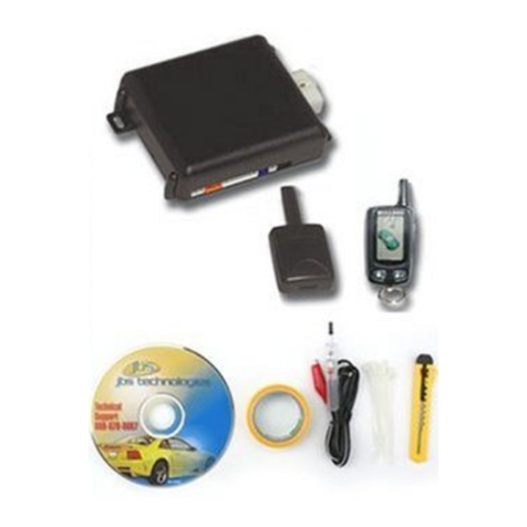
Your Bulldog Security remote starter is equipped with an interactive
install CD and installation kit. The kit will consist of a computer
friendly test light, wire ties and a roll of tape. Use only the computer
friendly test light or volt meter when testing and probing wires.
For Technical assistance www.bulldogsecurity.com can provide
a detailed wiring diagram for your vehicle including additional helpful
install tips.
JBS Technologies
225 Technology Way
Steubenville Ohio 43 53
INSTALLATION TIPS AND A ESSORIES
2
. .
TABLE OF CONTENTS
3
INSTALLATION DIAGRAM ..........................................................7-8
H1: 6 PIN HEAVY GAUGE WIRING CONNECTION...........................9
H1/1 Violet Wire  Starter Output...................................................9
H1/2 & H1/3 Red Wire  +12V Power nput .....................................9
H1/4 Yellow Wire  gnition 1 Output ..............................................9
H1/5 Pink Wire  gnition 2 Output .................................................9
H1/6 Brown Wire  Accessory Output (Heater /ACC Output) .............10
H2: 5 PIN WIRE HARNESS ..........................................................10
H2/1 Red / White wire  Parking Light Relay Power nput .................10
H2/2 White wire  Parking Light Relay Output ................................10
H2/3 Black wire  System Ground.................................................10
H2/4 Brown wire  (-) 200ma Horn Output ....................................11
H2/5 Red wire  System Power.....................................................11
H3: BLACK 4-PIN CONNECTOR
FOR TWO-WAY TRANSCEIVER ANTENNA MODULE......................11
H5: 9 PIN BLACK WIRE HARNESS ...............................................11
H5/1 Grey wire  (-) Negative Safety Shut Down For Hood Pin Switch11
H5/2 Brown / Red wire  (+)
Positive Safety Shut Down Brake or Handbrake...........................12
H5/3 Black / White wire (-)
Neutral Safety Switch or (-) Remote Toggle Switch nput .............13
H5/4 Blue /White wire Not Used..................................................13
H5/5 Grey / Black wire  (-) Diesel Wait - To - Start nput ...............13
H5/6 Green wire  (-) Negative Door Pin Switch nput (Zone 3) ........13
H5/7 Violet Wire  (+) Positive Door Pin Switch nput (Zone 3).........14
H5/8 White / Black wire  (-) nstant Start & Turn Off nput .............14
H5/9 Violet / White wire  Tach nput or Oil Sensor Connection ....14-15
H6. 6 PIN DOOR LOCK CONNECTOR ............................................15
nstalling New Door Lock Actuator ................................................15
Type A Negative Trigger Door Lock System ..................................15
Type B Positive Trigger Door Lock System ...................................15
Type C 5-wire Door Lock System ................................................15
2 Steps Door Unlock Wire Connection
Type C 5 Wires Alternating Door Lock System ..............................16
Vacuum Operate Door Locking System ..........................................16
2 Steps Door Unlock Wire Connection
Type B Negative Switched Door Lock System ...........................16
D500 M 6/04
. .
TABLE OF CONTENTS
4
2 Steps Door Unlock Wire Connection
Type A Positive Switched Door Lock System 16
H7: 10-PIN WHITE WIRE HARNESS 17
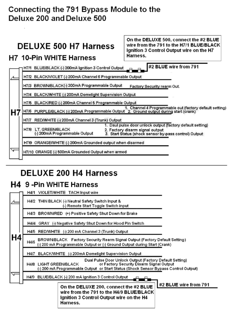
H7/1 Blue /Black wire  (-) 200mA Ignition 3 Control Output 17
H7/2 Black / Violet wire  (-)
200mA Channel 6 Programmable Output 17
H7/3 Brown / Black wire  (-) 200mA Programmable Output 17
Horn Output  (Factory Default Setting)
Factory Security Rearm Signal Output
H7/4 Black / White wire  (-) 200mA
Dome Light Supervision Output 18
H7/5 Black / Red wire  (-) 200mA
Channel 5 Programmable Output 18
H7/6 Violet / Black wire  (-) 200mA Programmable Output 18
Channel 4 Programmable Output  (Factory Default Setting)
Ground Output During Start (Crank)
H7/7 Red / White wire  (-) 200mAChannel 3 (Trunk) Output 19
H7/8 LT Green / Black wire  (-) 200mA Programmable Output 19
Dual Pulse Door Unlock Output
Factory Security Disarm Signal Output (Factory default setting)
Start Status (Shock Sensor By-Pass Control) Output 19
H7/9 Orange / White wire (-)
200mA Grounded Output When Disarmed 20
H7/10 Orange wire  (-) 200mA Grounded Output When Armed 20
H8. 2 PIN BLUE CONNECTOR FOR THE VALET SWITCH 20
H9. 2 PIN WHITE CONNECTOR
FOR THE LED STATUS INDICATOR 20
PROGRAMMING & TESTING:
A. AUTOMATIC MANUAL TRANSMISSION VEHICLE 21
B. PROGRAMMING A NEW TRANSMITTER 21
C. FEATURES PROGRAMMING 21-22
Alarm Feature #1 Programming 22-23
3 / 30 seconds Delay Door Ajar Error Chirp
Alarm Feature #2 Programming 23-24
Comfort Feature
Alarm Feature #3 Programming 24-26
Channel 4 (5 / 6) Timer Control Output Programming
Ground Output During Start (Crank) Programming
. .
TABLE OF CONTENTS
5
This remote starter with keyless entry system is designed to be
installed on fuel injected vehicles only.
 This system must be installed and wired through a safety switch
to assure that it will not start in any forward or reverse gear.
 Some automatic transmission vehicles [mainly older GM models
with a ur le starter wire] have a mechanical-ty e ark mechanism
instead of an electrical safety switch. The mechanical ty e does
not interru t the starter circuit when the transmission is any gear
and does not offer the 100% level of safety required for remote
starting ur oses. Therefore, you must create a circuit that will
revent the remote starter from engaging when the key is in the
ignition.
 Once you install this system, you must verify that the vehicle will
not start any forward or reverse gear.
IMPORTANT NOTICE
Start Feature #1 Programming ................................................27-28
Safe Start (Child Safety Mode)
Tem erature Start Programming
Start Feature #2 Programming ................................................28-29
Engine Checking TACH.  RPM Learning & Testing .......................30
Engine Checking Voltage  Start Timer Set-u & Testing ..............31
Engine Checking Oil Sensor  Start Timer Set-u & Testing ..........32
Turbo Mode
Range Check
RETURN TO FACTORY DEFAULT SETTING ....................................33
SHUTDOWN DIAGNOSTICS.....................................................34-35
TESTING YOUR INSTALLATION ..............................................35-39
Test the Brake shutdown circuit
Test the Hood Pin shutdown circuit
Neutral Start Safety Test
Mechanical Neutral Safety Switch Considerations
Park/Neutral ECM In ut
Key In Sensor Circuits
. .
6
IMPORTANT NOTICE
COMPONENTS
 1- Main Control Module
 1- Five Button LCD Remote
Transmitter
 1- 6 Pin Ignition Harness
 1- 5 Pin Harness
 1- 1 Pin Mini Output Harness
 1- 9 Pin Mini Input Harness
 1- 2 Pin Valet Switch
 1- 2 Pin Led Light Harness
 1- 4 Pin Antenna Harness
 1- 6 Pin Door Lock Harness
 1- Hood Switch
 1- Hood and Window Decal
 1- Installation Manual
 1- Owners Manual
 Read the operation manual for operating and programming routine.
 Do not install any component near the brake, gas pedal or steering
linkage.
 Most vehicles have an SRS air bag system. Use extreme care and
do not probe any wires of the SRS system. These wires will almost
always be located inside a bright yellow tube located near the
steering wheel column.
 Check behind panels before drilling any holes. Ensure that no wiring
harness or other components are located behind the panels that
would otherwise be damaged.
 Do not use conventional crimp lock or bullet connectors on any
wiring.
 Do not disconnect the battery if the vehicle has an anti-theft radio
or is equipped with an airbag. Doing so may cause a warning light
to be displayed and the radio to stop functioning.
 Do not leave the interior or exterior lights on for an extended
period of time. Remove the dome light fuse from the vehicles fuse
box.
 Do not mount the control module until all connections have been
made and the unit is programmed and tested.
 Finally place the warning sticker under the hood when the installation
is completed.
. .
7
INSTALLATION DIAGRAM
6 Pin White
Connector for
Door Lock and
Door Unlock
Connection
6
. .
8
WIRING HARNESSES
Keep all wiring away from moving engine parts, exhaust pipes and high-
tension cable. Tape wires that pass through holes on the firewall to prevent
fraying. Watch out for sharp edges that may damage wires and cause
short circuits.
CAUTION: Do not connect the wire harness to the control
module until all wirin to vehicle is complete.
. .
9
WIRING CONNECTIONS
H1: 6-PIN HEAVY GAUGE WIRING CONNECTIONS:
Remember that the system is designed to duplicate the same functions
of the ignition key switch! Since this installation will require analysis of
the ignition switch functions, we recommend making the H1 harness
connections directly to the ignition switch wires.
H1/1 VIOLET Wire(Starter Cran Output)
onnect the VIOLET wire to the starter crank wire at the ignition switch
harness. This wire show +12 volts when the ignition switch is turned
to the start or cran  position only. This wire will test 0 volts in all
other ignition switch positions.
H1/2 and H1/3 RED Wires (2)-(+12V Power Input)
Remove the two 20A fuses prior to connecting these wires and do not
replace them until the satellite harness has been plugged into the control
module. These two wires are the source of current for all the circuits the
relay satellite will energize. They must be connected to a high current
source. Since the factory supplies (+) 12V to the key switch, it is
recommended you make your connections there.
Note: If the factory supplies two separate (+) 12V feeds to the ignition
switch, connect one RED wire of the satellite to each feed at the switch.
H1/4 YELLOW Wire  (Ignition 1 Output)
onnect the YELLOW wire to the ignition one wire from the ignition
switch. The ignition wire should receive "12 volts" when the ignition
key is in the "on" and "start" or cran  positions. When the ignition
is turned "off", the ignition wire should receive "0" voltage. The YELLOW
wire must be connected.
H1/5 PINK Wire  (Ignition 2 Output)
Some vehicles have 2 ignition wires that must be connected. Attach the
PINK wire to the ignition 2 wire from the ignition switch. The ignition
wire should receive "+12 volts" when the ignition key is in the "on" or
run and "start" or cran  positions. When the ignition is turned to
the"off" position this wire will show "0" voltage. If the PINK wire is
not used, cap or tape the end of the wire.
. .
10
WIRING CONNECTIONS
H1/6 BROWN Wire Accessory Output (Heater /AC Output)
Connect the BROWN wire to the Accessory/Heater-Blower wire in the
vehicle that powers the Heater/AC system. The Accessory/Heater-Blower
wire will show  12 volts when the ignition switch is turned to the
accessory(some vehicle) on and run positions and will show
0 volts when the key is turned to the off and start or crank
positions. On some vehicles there will often be more than one
Accessory/Heater-Blower wire in the ignition harness. The correct
Accessory/Heater-Blower wire will power the vehicles Heater/AC system.
Note: Some vehicle may have separate wires for the blower motor and
the air conditioning compressor such as Ford products. In such cases
it will be necessary to add a relay to power the second Accessory/Heater-
Blower wire if your vehicle does not have a Ignition 2 wire use the
Ignition 2 Output (H1/5 PINK) wire from the remote starter to power
up the second Accessory/Heater-Blower wire.
H2: 5-PIN WIRE HARNESS:
H2/1 RED / WHITE Wire (Parking Light Relay Input)
The RED/WHITE wire is the input for the parking light relay. This
wire will determine the output polarity of the parking light relay.
If your vehicle requires 12volts to power the parking light circuit you
will not need to connect this wire. This wire is already connected to the
12 volt constant RED wire in the same harness.
If your vehicles parking light circuit operates on a switched (-) negative
ground then cut the RED/WHITE wire from the RED wire and attach
it directly to a ground source. Note: Make sure to tape the RED wire
at the cut location.
H2/2 WHITE Wire (Parking Light Relay Output)
Connect the WHITE wire to the wire that powers the parking light
circuit on the vehicle. The WHITE parking light wire is rated at 10amps
max and should not exceed this current. If your vehicles parking light
system requires more then 10amps you must add a relay to power
the parking light system.
H2/3 BLACK Wire (System Ground)
This is the main ground connection of the control module. Make this
connection to a solid section of the vehicles frame ground.
. .
11
WIRING CONNECTIONS
H2/4 BROWN Wire (Horn Output)
The BROWN wire will provide a (-) negative output for the vehicles
horn or optional siren hookup.This wire is a transistorized low current
200mA output, and should only be connected to the low current ground
output from the vehicle s horn switch.
H2/5 RE Wire (System +12volt Constant Power)
Connect the RE wire to a constant +12 volt source.
H3: 4-PIN BLACK CONNECTOR (Windshield Receiver / Antenna)
The windshield receiver/antenna mounts on the inside of the front windshield.
We suggest you mount it on the lower left or upper left-hand side of
windshield.
Warning! Do not mount in such a manner that it obstructs the drivers
view.
- The receiver/antenna whip must be vertical.
- Remove the protective tape backing and clean the are around the glass
where you are installing.
- Carefully align the receiver/antenna and apply to windshield.
- Route the black connector wire behind the trim and connect to
receiver/antenna.
- Connect the other end to the control module.
- Special considerations must be made as some newer vehicles utilize
a tinted window glass that can effectively reduce the range.
H5 9-PIN BLACK WIRING HARNESS:
This wire provides an instant shutdown for
the remote start, whenever it is grounded.
Connect the wire to the hood pin switch
previously installed. This wire must be
routed though a grommet in the firewall
and connected to the hood pin switch.
If the pin switch is to be used with an
alarm system, connect this wire with diode.
H5/1 GREY Wire (-) (Negative Safety Shut own For Hood Switch)
. .
12
WIRING CONNECTIONS
H5/2 BROWN/RED (Positive Safety Shut Dow or Brake I put)
This wire provides an instant shutdown for the remote starter whenever
it recieves a +12volts.Connect this wire to the output or cold side of
the brake switch that shows +12volts only when the brake is pressed.
See below diagram
Ma ual Tra smissio : When you are in manual transmission gear mode,
you also need to connect the BROWN / RED wire into the handbrake switch.
n isolation diode must be used for handbrake switched light circuits and
brake light circuit. Most handbrake wire will show +12V at rest when the
ignition is on and ground when you set the handbrake. However, if the
handbrake wire shows 0V while the handbrake is at rest, you will need to
add a relay as below.
This wire provides an instant shutdown for
the remote start, whenever it receives
+12volts. If the brake lights switch in the
vehicle switches +12 volts to the brake light circuit,
connect this wire to the output side of the brake
switch. This will allow the remote start to shut
down if an attempt is made to operate the vehicle without
the key while running under the control of the remote start. In most vehicles,
in order to shift gear, the brake pedal must be depressed. The brake input
will in turn cause the remote start unit to shut off. (See diagram.)
. .
13
WIRING CONNECTIONS
H5/3 THIN BLACK Wire ( Remote Start Enable or Nuetral Sa ety
Input)
When the THIN BLACK wire is grounded, the remote start unit is
operable. When this wire is open from ground, the remote starter is
disabled.
1. The optional remote start toggle switch can be added on to this wire
to temporally disable the remote starter. This feature is useful if the
vehicle is being serviced or stored in an enclosed area.
2. This wire can also be connected to the neutral safety switch wire in
the vehicle.
IMPORTANT NOTE: Directly connect the THIN BLACK wire to
ground when not being used. The remote starter will not start i
this wire is not grounded.
H5/4 BLUE / WHITE Wire (Not Used)
H5/5 GREY/BLACK (Negative Diesel Wait to Start Input)
The GREY/BLACK wire is a (-) negative input for diesel vehicles only.
This wire will attach directly to the wait to start bulb on the dashboard,
or on some vehicles the CM module. You must locate and test the wire
that will provide a ground signal when the wait to start light is on. The
correct wire will provide a (-) negative ground signal when the bulb is
on and +12volts positive when the bulb is out. There are some vehicles
that will have the opposite configuration and you will need to wire a relay
to convert the polarity. (See diagram example below)You must program
the control module for diesel mode. (See programming instructions.)
H5/6 GREEN (Negative Door Input) (Must be used or manual
transmissions)
The GREEN wire is the (-) negative ground trigger input for negative style
door circuits. This green wire will attach to the wire in the vehicle that
provides a (-) negative ground when any of the doors are opened. The
same wire in the vehicle will provide +12volts positive or 0 voltage when
the doors are closed.
. .
14
WIRING CONNECTIONS
H5/7 VIOLET (Positive Door Input) ( ust be used for manual
transmissions)
The VIOLET wire is the positive trigger input for +12volt positive style
door circuits. The VIOLET wire will attach to the wire in the vehicle that
provides +12volt positive when the door is opened. The same wire in
the vehicle will provide 0 voltage or negative ground when the doors
are closed. This type of door circuit is most common with Ford vehicles.
H5/8 WHITE/BLACK (Instant Start and Stop Input)
The WHITE/BLACK wire will activate and deactivate the remote starter
when it sees a momentary (-) negative ground.
This wire is used for testing purposes and to activate the remote starter
from another source. (See Alarm Feature #3 Programming Chart)
H5/9 VIOLET / WHITE Wire (Tach. Input or Oil Sensor Connection)
(Tach Input Connection)
Note: No connection of this wire is required, if you are using the voltage
checking type mode. This input provides the remote start system with
information about the engine s revolutions per minute (RPM). It can be
connected to the (-) negative side of the coil in vehicle with conventional
coils. To test for a tachometer wire, a multi-meter capable of testing AC
voltage must be used. The tach wire will show between 1V and 6V AC
at idle, and will increase as the engine RPM increases. In multi-coil ignition
systems, the control module can learn individual coil wires.
I PORTANT! Do not test for tach wires with a test light or logic probe.
How to find a tach wire with your multi-meter
1. Set the ACV or AC voltage (12V or 20V is fine.)
2. Attach the (-) probe of the meter to chassis ground.
3. Start and run the vehicle.
4. Probe the wire you suspect of being the tach wire with the red probe of
the meter.
5. If this is the correct wire the meter will read between 1V and 6V.
I PORTANT NOTE: You must program the Tach Signal before
trying to remote start.
Oil Sensor Signal Connection
Locate the wire connected to the oil sensor.
Negative Oil Sensor Connections: +12volts to +14volts will show on
the multimeter when the ignition switch is turned to the ON position in
the key cylinder and +2volts to + 3volts when the motor is running.
. .
15
WIRING CONNECTIONS
Positive Oil Sensor Connections: +2volts to + 3volts will show ON
the multimeter when the ignition switch is turned to the on position in the
key cylinder and +12volts to + 14volts when the motor is running.
IMPORT NT NOTE: You must program for oil sensing type before
trying to remote start. (See programming start feature #2.)
H6: 6-PIN DOOR LOCK CONNECTOR:
. .
16
WIRING CONNECTIONS
VACUUM OPERATED DOOR
LOCKING SYSTEM:
TYPICAL OF MERCEDES BENZ
AND AUDI.
Locate the wire under the driver's
kick panel. Use the voltmeter
connecting to ground, verify that
you have the correct wire with the
doors unlocked, the voltmeter will
receive "12 volts". Lock the doors
and the voltmeter will read " volt".
Move the alligator clip to +12V and
the voltmeter will receive "+12 volts". Cut this wire and make your
connections. Be sure to program the door lock timer for 3.5 seconds.
. .
17
WIRING CONNECTIONS
H7/2 BLACK/VIOLET (Timer Control Channel Programmable
Output)
The BLACK/VIOLET wire provides a 200mA (-) programmable (-)
negative ground output for a variety of optional devices The output on
the BLACK/VIOLET wire is programmable from 1 to 120 seconds. (See
Alarm Feature #3 Programming Chart.)
This wire can be used to open a sunroof, or any power device you choose
to control The BLACK/VIOLET wire must be wired to a relay when
powering any devices
Note: factory default setting is a 1 second momentary (-) negative
ourput. (See Alarm Feature #3 Programming Chart.)
To activate this feature press the transmitter and buttons at the
same time
H7/3 BROWN/BLACK (Factory Rearm Output)
The BROWN/BLACK wire provides a 200mA (-) negative output for
hooking up to the vehicles factory rearm wire For factory rearm a (-)
negative pulse is provided after the remote starter times out or is shut
down with the transmitter
H7: 10-PIN WHITE WIRING HARNESS:
H7/1 BLUE / BLACK Wire (Ignition 3 Output)
This wire provides a 200mA (-) negative ground output that becomes
active 4 seconds before the remote start unit initializes, and remains
grounded while running
Ignition 3 output:
Some newer vehicles use a
third ignition wire which is
required to start and keep
the vehicles engine running
If this is the case, wire an
IGN 3 relay (not supplied) as
shown: Do not connect
any vehicle circuits together, they
are isolated for a reason
. .
18
WIRING CONNECTIONS
H7/4 BLACK/WHITE (Dome Light Super ision Output)
The BLACK/WHITE wire provides a 200mA (-) negati e output for 30
seconds when the doors are unlocked using the transmitter. The
BLACK/WHITE wire will also flash the dome light circuit for the same
duration as the siren when violated. Note: If not attaching the
BLACK/WHITE wire directly to the BCM (Body control module) a
relay must be used to power the dome light circuit.
H7/5 BLACK/RED (Timer Control Channel 5 Programmable Output)
The BLACK/RED wire provides a 200mA (-) negati e programmable
ground output for a variety of optional devices. The output on the
BLACK/RED wire is programmable from 1 to 120 seconds. (See Alarm
Feature #3 Programming Chart)
This wire can be used to open a sunroof or any power device you choose
to control. The BLACK/RED wire must be wired to a relay when powering
any devices. Note: factory default setting is a 1 second momentary
ground. (See Alarm Feature #3 Programming Chart)
To activate this feature press the transmitter and buttons at the
same time.
H7/6 VIOLET/BLACK (Timer Control Channel 4 / Key Sensor Output)
The VIOLET/BLACK wire provides a 200mA (-) negati e programmable
ground output for a variety of optional devices. The output on the
black/violet wire is programmable from 1 to 120 seconds. (See Alarm
Feature #3 Programming Chart)
This wire can be used to open a sunroof or any power device you choose
to control. The VIOLET/BLACK wire must be wired to a relay when
powering any devices.
Note: factory default setting is a 1 second momentary ground.
(See Alarm Feature #3 Programming Chart)
Note: this wire can also be programmed as a second start crank
output. . (See Alarm Feature #3 Programming Chart)
Some vehicles require a second starter wire to be energized or on certain
GM vehicles what is known as the bulb check wire must receive a ground
signal while the starter is cranking. When using this wire as a second
start wire (Most Nissan vehicles) a relay must be used to energize this
circuit. Press the transmitter and buttons at the same time.
. .
19
WIRING CONNECTIONS
H7/7 RED/WHITE (Channel 3 Trunk Output)
The RED/WHITE wire will provide a 1 second 200mA (-) negati e
ground pulse output by activating channel 3 on the transmitter for 2
seconds. This feature will allow trunk release or other optional devises
by remote transmitter. Note: If not attaching the RED/WHITE wire
directly to the BCM (Body control module) a relay must be used
to power the trunk or de ice being energized.
H7/8 LT. GREEN / BLACK Wire ( Step 2 Door Unlock / Factory
Disarm / Shock sensor Bypass)
Dual Pulse Door Unlock Output 
The dual pulse door unlock feature will work for the most fully electronic
door lock circuits. hen wired for this feature, pressing the disarm (or
unlock) button one time will disarm the alarm and unlock the driver's
door only. If you press disarm (or the unlock) button two times within
3 seconds, the alarm will disarm and all the doors will unlock. (See Alarm
Feature #3 Programming Chart.)
Factory Security Disarm Signal Output  (Factory Default Setting)
This wire is designed to disarm a factory installed security system. This
wire sends a (-) negati e 1 second pulse upon a remote start and remote
door unlocking. Some factory systems must be disarmed to allow remote
starting. In most cases, this wire may be connected directly to the factory
alarm disarm wire. The correct wire will show nagative ground when the
key is used to unlock the doors or trunk. This wire is usually found in the
kick panel area in the wiring harness coming into the car body from the
door. (See Alarm Feature #3 Programming Chart)
Start Status (Shock Sensor By-Pass Control) Output
This wire is designed to by-pass a shock sensor module. This wire will
supply an output at all times the remote start is operating plus an
additional 3 seconds after the remote start unit turn off. (See Alarm
Feature #3 Programming Chart.)
. .
20
WIRING CONNECTIONS
7/9 ORANGE/WHITE (Ground Output When Disarmed
The ORANGE/WHITE wire provides a 200mA (- negative output
when the security system is disarmed. This output can be used for
activating optional devises such as memory positions for power seats.
Note: If not attaching the orange/white wire directly to the BCM
(Body control module a relay must be used to power the device
being energized.
H7/10 Orange (Starter Disable Relay Output
The ORANG will provide a 500mA (- negative output when the security
system is armed. A relay with a diode across the coil must be used when
interrupting the starter wire. If attaching more then one device to this
wire you must diode isolate each device.
H8: 2-PIN BLUE CONNECTOR FOR THE PROGRAM / VALET SWITCH:
Select a mounting location for the switch that is hidden but easily
accessible to the driver of the vehicle. Mount the valet switch in a hidden
but accessible location. Route and plug in the valet switch wires to the
control module.
H9: 2-Pin White Connector
The L D light should be mounted in a highly visible location in the dashboard,
center console or dashboard face. Provide for at least a 6mm space behind
the L D light. Once a suitable location is chosen, drill a 6mm hole then
press the L D housing into the hole. Route the L D wires to the control
module and plug it in.
H7/9
H7/10

Other manuals for DELUXE 500

4

Other Bulldog Security Car Alarm manuals

Bulldog Security 901 Instruction Manual

Bulldog Security

Bulldog Security 901 Instruction Manual

Bulldog Security Pro-Series 7002 User manual

Bulldog Security

Bulldog Security Pro-Series 7002 User manual

Bulldog Security 2030 User manual

Bulldog Security

Bulldog Security 2030 User manual

Bulldog Security 1001 Instruction Manual

Bulldog Security

Bulldog Security 1001 Instruction Manual

Bulldog Security 1101 User manual

Bulldog Security

Bulldog Security 1101 User manual

Bulldog Security 2003 Instruction Manual

Bulldog Security

Bulldog Security 2003 Instruction Manual

Bulldog Security 5002PRO User manual

Bulldog Security

Bulldog Security 5002PRO User manual

Bulldog Security 1402 Instruction Manual

Bulldog Security

Bulldog Security 1402 Instruction Manual

Bulldog Security Delux 500 User manual

Bulldog Security

Bulldog Security Delux 500 User manual

Bulldog Security MA1000 Operation and maintenance manual

Bulldog Security

Bulldog Security MA1000 Operation and maintenance manual

Bulldog Security DELUXE 500 User manual

Bulldog Security

Bulldog Security DELUXE 500 User manual

Bulldog Security 801 Instruction Manual

Bulldog Security

Bulldog Security 801 Instruction Manual

Bulldog Security DELUXE 500 User manual

Bulldog Security

Bulldog Security DELUXE 500 User manual

Bulldog Security RS82 Instruction Manual

Bulldog Security

Bulldog Security RS82 Instruction Manual

Bulldog Security 3001 Instruction Manual

Bulldog Security

Bulldog Security 3001 Instruction Manual

Bulldog Security 802 User manual

Bulldog Security

Bulldog Security 802 User manual

Bulldog Security 2002 Instruction Manual

Bulldog Security

Bulldog Security 2002 Instruction Manual

Bulldog Security RS602E Instruction Manual

Bulldog Security

Bulldog Security RS602E Instruction Manual

Bulldog Security 2001 Instruction Manual

Bulldog Security

Bulldog Security 2001 Instruction Manual

Bulldog Security 1402 User manual

Bulldog Security

Bulldog Security 1402 User manual
Bulldog Security DELUXE 500 User manual
Bulldog Security

Bulldog Security DELUXE 500 User manual

Bulldog Security DELUXE 200 User manual
Bulldog Security

Bulldog Security DELUXE 200 User manual

Bulldog Security 1101 Instruction Manual

Bulldog Security

Bulldog Security 1101 Instruction Manual

Bulldog Security DELUXE 500 User manual
Bulldog Security

Bulldog Security DELUXE 500 User manual

Popular Car Alarm manuals by other brands

Mongoose M60i Owner's operation manual

Mongoose

Mongoose M60i Owner's operation manual

CrimeStopper CS-2011RS Series III Super Rage installation instructions

CrimeStopper

CrimeStopper CS-2011RS Series III Super Rage installation instructions

Genius G3000 Link manual

Genius

Genius G3000 Link manual

Eaglemaster E2 instruction manual

Eaglemaster

Eaglemaster E2 instruction manual

Omega Vehicle Security K9-6ATV2 owner's manual

Omega Vehicle Security

Omega Vehicle Security K9-6ATV2 owner's manual

Audiovox Prestige Platinum APS-150-A owner's manual

Audiovox

Audiovox Prestige Platinum APS-150-A owner's manual

LaserLine 996 kit installation guide

LaserLine

LaserLine 996 kit installation guide

Magicar M902F user guide

Magicar

Magicar M902F user guide

Viper 4103XV installation guide

Viper

Viper 4103XV installation guide

Carbine PLUS-4700 installation manual

Carbine

Carbine PLUS-4700 installation manual

Directed Electronics Python 880XP installation guide

Directed Electronics

Directed Electronics Python 880XP installation guide

Directed Electronics Python 990 owner's guide

Directed Electronics

Directed Electronics Python 990 owner's guide

CaraWarn Secure-Sleep-I instructions

CaraWarn

CaraWarn Secure-Sleep-I instructions

Audiovox RO9801 owner's manual

Audiovox

Audiovox RO9801 owner's manual

Cobra GLOBE 3100 Fitting instructions

Cobra

Cobra GLOBE 3100 Fitting instructions

Viper 5606V owner's guide

Viper

Viper 5606V owner's guide

Cobra 4625 user manual

Cobra

Cobra 4625 user manual

Omega Excalibur AL-1810-EDP Operation manual

Omega

Omega Excalibur AL-1810-EDP Operation manual

manuals.online logo
manuals.online logoBrands
  • About & Mission
  • Contact us
  • Privacy Policy
  • Terms and Conditions

Copyright 2025 Manuals.Online. All Rights Reserved.