Burcam 450455 User manual

450455
.
PUMPS
www.burcam.com
COMPATIBLE WITH ANY TYPE OF WATER PUMPING SYSTEM.
© 2016 BURCAM Printed in Canada 450456T.2
ALERTS YOU
before any water damage
occurs from your sump
or sewage tank
Instructions must
remain with
installation.
IMPORTANT : Your “Wi-Fi Water Watcher” has a function to alert you in case of a loss of connectivity to our server.
Nevertheless, to get the most out of your “Wi-Fi Water Watcher”, a back-up battery for your router and modem is
required to maintain connectivity in case of a power failure. This kind of back-up system is available from all reputable
computer equipment retailers. We highly recommend adding such a system to your existing computer equipment if you
have not already done so.

P.2
Safety and supplementary information
This product has been carefully packaged at the factory to prevent damage during
shipping. However, occasional damage may occur due to rough handling. Carefully
inspect this product for damages that could cause failures. Report any damage to
your carrier or your point of purchase.
SAFETY INSTRUCTIONS
This ne product that you have just purchased is designed from the latest in
material and workmanship. Before installation and operation, we recommend the
following procedures:
• CHECK WITH YOUR LOCAL ELECTRICAL AND PLUMBING CODES TO ENSURE YOU COMPLY
WITH THE REGULATIONS. THESE CODES HAVE BEEN DESIGNED WITH YOUR SAFETY IN
MIND. BE SURE YOU COMPLY WITH THEM.
• WE RECOMMEND THAT A SEPARATE CIRCUIT BE LEAD FROM THE HOME ELECTRICAL
DISTRIBUTION PANEL PROPERLY PROTECTED WITH A FUSE OR A CIRCUIT BREAKER. THIS
PRODUCT HAS TO BE SECURELY PLUGGED INTO A PROPER ‘GFCI’ ELECTRICAL OUTLET.
CONSULT A LICENSED ELECTRICIAN FOR ALL WIRING.
• WHEN SUPPLIED, THE GROUND TERMINAL ON A THREE-PRONG PLUG SHOULD NEVER BE
REMOVED. IT IS SUPPLIED AND DESIGNED FOR YOUR PROTECTION.
• NEVER MAKE ADJUSTMENTS TO ANY ELECTRICAL APPLIANCE OR PRODUCT WITH THE
POWER CONNECTED. DO NOT ONLY UNSCREW THE FUSE OR TRIP THE BREAKER, REMOVE
THE POWER PLUG FROM THE RECEPTACLE.
This product was developed to notify you when a liquid level
reaches a critical point. However, it does not offer any guarantee
that messages will be transmitted due to the nature of the product
itself. There are several steps involved in the transmission of a
message between the alarm and your smart phone including your
router and your modem, your internet access, several servers, our internet access,
our provider for text message transmission, your cell phone service provider, etc.,
as well as any other device within the transmission network between the Wi-Fi
Water Watcher and your smart phone. Although all devices within the transmission
network have a high degree of reliability, one of them may stop functioning
due to factors that are beyond our control, which may prevent messages from
being transmitted. It is your responsibility to regularly check that your product
is functional.
A detailed manual is available at www.burcam.com.
Search for product model 450455.

.
P.3
Safety and supplementary information
This product does not require any internal maintenance.
Opening this unit voids the warranty.
On-off button.
Power supply is
connected when
‘‘LED’’ is on.
Battery is fully charged when
‘‘LED’’ is ashing slowly. —
Float sensor well connected
when ‘‘LED’’ is ashing slowly. —
Power supply port.
Alarm reset button (Float sensor must
be pointing downwards prior to reset). —
Push and hold until it beeps (± 3 seconds)
Float port.
Transmission test button.
Push and hold until it beeps (± 3 seconds)
Unit reset button : Wi-Fi connection
is reset when this button is pushed
in and held down until the two
beep signal is heard. —
This may take up to 15 seconds.
The battery needs to be recharged
when ‘‘LED’’ is ashing rapidly.
When ‘‘LED’’ is ashing
rapidly the oat is not well
connected to the device
or the oat is missing.
Connected to Wi-Fi network
when ‘‘LED’’ is ashing.
Connected to internet when
‘‘LED’’ is on.

P.4
Quick set-up of the Wi-Fi Water Watcher
To connect the alarm controller to your router, you need a computer, a tablet or a smart
phone having a Wi-Fi connectivity and a Web browser installed.
** Before you begin, have your local Wi‑Fi name (SSID) and password handy, as
well as the encryption method (normally WPA2PSK) and encryption algorithm
(normally AES) of your router. **
Step 1. To connect the alarm controller to your local Wi‑Fi router.
A. For initial set up purposes, install the alarm controller within 15 feet (5 meters) of your
Wi-Fi router.
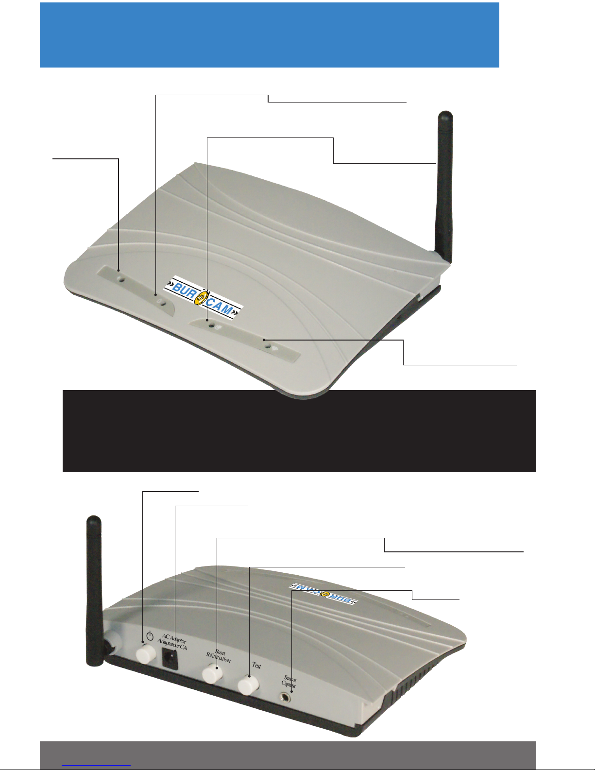
B. Connect the enclosed power supply to the appropriate port on the control panel at the
rear of the alarm controller and then plug it into a 115V AC receptacle.
C. Connect the enclosed oat sensor to the appropriate port on the control panel of the
alarm controller. Keep the oat sensor pointing downwards.
D. Push the On/Off button on the control panel. The left LED will turn on to conrm the
unit is powered by the power supply.
E. Wait one minute then push the RESET button on the control panel until you hear the
two-beep signal. This may take up to 15 seconds. Then release the button and you will
hear the two-beep signal once more. Wait ten seconds then turn off the unit by pressing
the On/Off button. Wait thirty seconds then push the On/Off button again. The unit will
restart with its hot spot activated. It is now ready to be connected to the Wi-Fi network.
F. Using a computer, a tablet, or a smart phone, connect it to the alarm controller’s hot
spot. This hot spot will appear on your available Wi-Fi networks as WATERALARM .
Select it and enter the BURCAM15 password (case sensitive — all uppercase letters).
You are now connected to the hot spot.
G. Open your web browser and enter the web address (URL) 10.10.100.254 in the address
bar of your web browser to open the set-up page of the alarm controller.
H. Enter the Username admin (case sensitive) and the Password admin . Then click on
Log In. You now have access to the alarm controller set-up page.
I. Click on Work Mode on the left menu and select STA mode, then click on Save only.
Do not click on Restart or Back.
J. Click on STA Setting on the left menu. Then, replace the Wi-Fi name (SSID) by your
local router Wi‑Fi name (case sensitive). You may also scan to list the available Wi-Fi
networks in range and select your network. Since no password is entered, click on the
OK button on the warning window. Select the encryption method of your network
generally WPA2PSK and the encryption algorithm generally AES and enter your
Wi‑Fi network password in the appropriate eld, then click on Save .
K. Click on Restart to allow your alarm controller to connect to your Wi-Fi network.
L. Wait until the far right LED turns on to conrm that the alarm controller is connected to
the internet. A ashing right LED indicates that the unit is connected to the WI‑FI router only.
M. If ever the far right LED does not turn on, you have probably not selected the
appropriate encryption method and/or encryption algorithm for your router. Find the
correct information and re-start the process at the line D.
N. To nalise the connection to your router, press the On/Off button, wait thirty seconds
then push the On/Off button again. This is to conrm that the unit reconnects
automatically to your Wi-Fi network.

.
P.5
Step 2. To congure the system manager to receive the messages.
AGo to www.burcam.com .
B. Click on the Wi‑Fi Water Watcher set‑up button.
C. Enter the serial number in the appropriate eld and click OK (ID code on the label
under the unit).
D. When your serial number is validated, click on create your parameters .
E. Choose a password that you will remember and enter it as your access code. Enter the
password a second time and click on validate.
F. Enter up to three email addresses and three phone numbers (for USA and Canada only)
which will receive the messages. Check the ‘‘I conrm” box and click on submit .
G. If desired, you can return to the line 2B and enter your serial number and password to
update the email addresses and phone numbers at your convenience.
Step 3. To test the transmissions.
A. Push the test button on the control panel of the alarm controller. You will receive the
test message within 2 minutes.
B. Test that the oat sensor is functional by lifting up the oat sensor to trigger the high
level alarm. Upon reception of the high level alarm message, reposition the oat sensor
so that it is pointing downwards and press the reset button to receive the alarm reset
conrmation message. You may reset at any time, but you will still receive the high
water level message three times at ve‑minute intervals even after resetting the unit.
You can now install the unit near the sump, sewage, or liquid container to monitor
abnormally high liquid levels. Set the oat sensor to turn the alarm on 1” above the highest
normal liquid level of the application.
MY SERIAL # :
MY WI‑FI NAME (SSID) :
MY PASSWORD :
ENCRYPTION METHOD :
ENCRYPTION ALGORITHM:
YOUR INFORMATION

P.6
A “TRANSMISSION TEST” message is sent when the test button
of the control panel is pushed.
A “POWER SOURCE CHANGE” message is sent when the power
source changes from 115V to the battery back-up (if the 115V
power supply stops powering the unit).
A “LOW BATTERY” message is sent when the battery needs to
be recharged.
A “HIGH LIQUID LEVEL” message is sent when the oat lifts
up and triggers the alarm. This message is automatically sent a
second time ve minutes after the original message and a third
time ten minutes after the original message.
A “HIGH LIQUID LEVEL REMINDER” message is sent every fteen
minutes until the unit is reset. This message is only sent after the
initial “high liquid level” message has been sent and if the unit has
not been reset.
A “RESET CONFIRMATION” message is sent when the reset
button of the control panel is pushed (oat sensor must be
pointing downwards prior to doing the reset).
A “CONFIRMATION OF ONGOING COMMUNICATION” message
is sent monthly to advise the owner that the connection to our
server is still active (on an hourly basis, the device sends a signal
to our server, which monitors when this message is received).
A “LOSS OF COMMUNICATION” message is sent when our server
stops receiving the hourly signal from your device.
2190 Dagenais Blvd. West
Laval, Quebec, Canada
H7L 5X9
TEL.: (514)337-4415
FAX.: (514)337-4029
TOLL FREE NUM.: 1-800 361-1820
Types of messages that can be received:
1.
2.
3.
4.
5.
6.
7.
8.
Table of contents