Burke TRI-FLEX II User manual

Burke Tri -Flex II Air Mattress
OPERATING INSTRUCTIONS
OPERATING INSTRUCTIONS MANUAL
Burke Low Air Loss Support System Alternating
Pressure System With Width Expansion
Using Real Time Pressure Monitoring (RTPM) Sensor Technology
US & INTERNATIONAL PATENTS PENDING
An FDA Registered Company, Products are FDA listed.
1800 Merriam Lane
Kansas City, KS 66106
1-913-722-5658
Email: [email protected]
www.burkebariatric.com
MADE IN USA
™

Burke, Inc.
1800 Merriam Lane
Kansas City, KS 66106 USA
www.burkebariatric.com
1-913-722-5658
pn 63568 rev 0117

1
TABLE OF CONTENTS
Danger, Caution and Warning 2
Manufacturer’s Liability 2
Explanation of Symbols Used 3
Control Unit Features 4
Support Surface Features 5
Technical Specications 6
Safety Instructions 9
Quick Reference Guide 11
Quick Operating Instructions 13
System Set-Up & System Diagram 14
Control Unit Set-Up 14
Operating Instructions 16
CPR Function 21
Patient Transportation 21
Cleaning Procedure 22
Care and Storage 23
Troubleshooting Guide 24
Warranty Information 25
SECTION PAGE
DO NOT USE IN THE PRESENCE OF FLAMMABLE ANESTHETICS
OR AN OXYGEN TENT AROUND THE CONTROL UNIT
Symbol used in the manual apply to hazards or unsafe practices
which could result in personal injury or property damage.
Do not use in the presence of smoking materials or open ame. Air
owing through air mattress will support combustion.
!
!
!

2
•Risk of electrical shock, do not remove control unit back cover.
• Refer servicing to qualied service personnel.
•Equipment should only be connected to a properly grounded three pronged wall outlet,
using 10 foot (305 cm) hospital grade power cord provided with the product.
MANUFACTURER’S LIABILITY
BURKE INC.’S original warranty on the Burke Low Air Loss Support System will remain
in effect during the warranty period, provided any changes, readjustments, or repairs have
been carried out by a factory authorized service center or a technician of BURKE INC., or
whenever the control unit and mattress system has been used according to the following oper-
ating instructions.
BURKE INC.’S liability under the warranty is the repair or replacement provided and,
in no event, shall BURKE INC.’S liability exceed the purchase price paid by the customer for
the product. Under no circumstances shall BURKE INC. be liable for any loss, direct, indirect,
incidental, or special damages arising out of or in connection with the use of this product.
INFORMATION CONTAINED IN THIS OPERATING INSTRUCTION MANU-
AL IS SUBJECT TO CHANGE WITHOUT ANY PRIOR NOTICE.
!
•Never drop or insert any object into any opening of the control unit.
•Please read this manual before operating Burke Low Air Loss Support
System. If you are unable to understand the manual fully or partially, please
contact your dealer or the manufacturer before attempting to use this equip-
ment. Otherwise personal injury or property damage may result.
In the event of mechanical damage or any issue which may compromise prod-
uct performance or patient safety, discontinue use and contact qualied ser-
vice personnel or distributor immediately.
!
!

3
EXPLANATION OF SYMBOLS USED ON THIS DEVICE
SYMBOL EXPLANATION
Turns unit On/ Off
MODE
Low Air
Loss
Max
Inate
POWER
Max Inate
Low-Air-Loss
Therapy
Time
Upright
LOCK
SOFT FIRM
Therapy
Time
Power Fail !
Low Pressure !
!
AP
ALARM
SCILENCE
MODE
Low Air
Loss
Max
Inate
Risk of electrical shock, do not remove back cover
Not for use in presence of ammable anesthetics.
Indicates that the degree of protection against
electrical shock is TYPE BF.
Attention: Instructs end user / care giver / operator
to refer to the manual
Indicates the point of attachment of the equipment
to earth (Grounding Point)
Mutes audio alarm
In the event of power failure or if the hose is
disconnected an audio /visual alarm will sound
Locks out all control unit functions to prevent
patient settings tampering
Boosts air pressures in the mattress to avoid
patient bottoming out
Sets Alternating Pressure Therapy times, 5, 10,
15, 20 minutes
Selects Static, Alternating Pressure (AP) therapy
or Upright (Fowler) mode
Supplies air into the low air loss section of the
mattress or into the optional special multi-cham-
ber air distribution layer in the top sheet
Inates mattress rapidly (30 minute timer)
Up or Down key adjusts patient comfort pressure levels.
Recycle waste electrical & electronic equipment

4
Burke Low Air Loss Support System
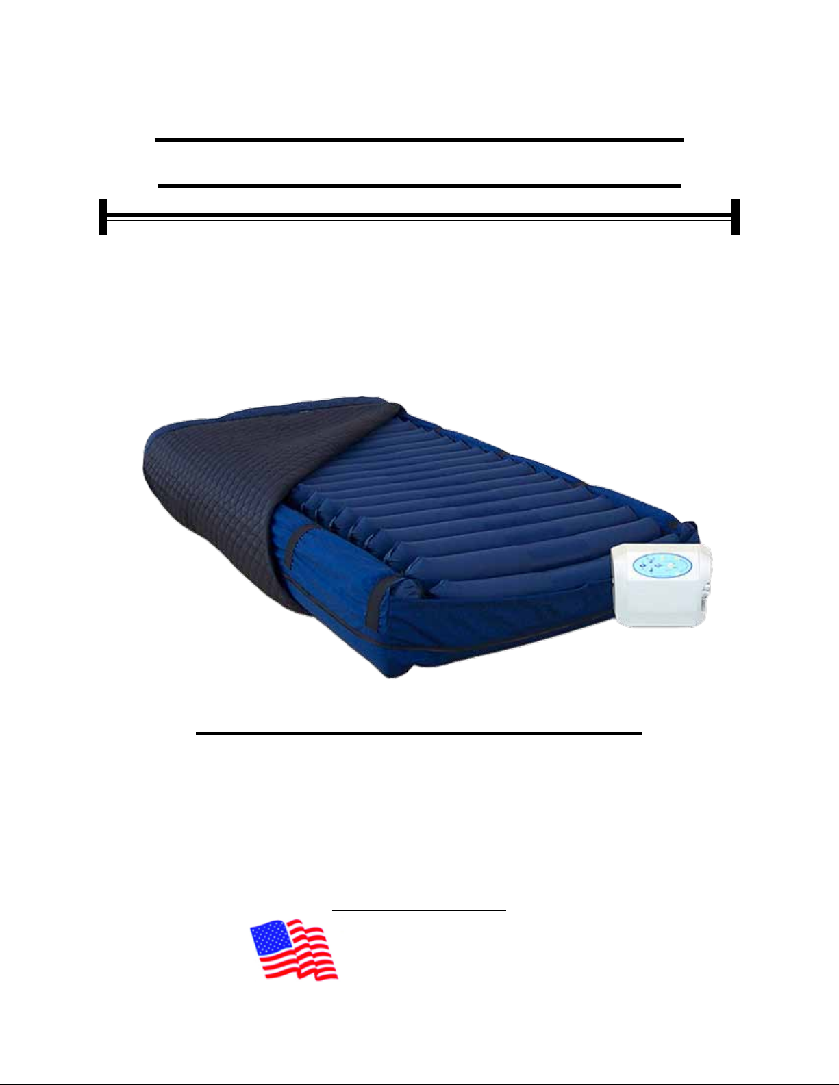
(Figure -1 Page 14):
The Burke Low Air Loss Support System is an alternating pressure & on-demand low air loss
system with width expansion side air bolsters, used to provide pressure reduction. It consists of a
control unit (A) which is used to inate a mattress replacement system (B) with width expansion side
air bolsters on each side. The control unit is designed to provide continuous static or alternating
pressure with low air loss relief at required patient comfort levels. The ABS/PVC blend enclosure
houses a medium output air pump (42~52 LPM), an alternating pressure solenoid valves, and a
micro-controller with pressure sensors, R.F auto fowler receiver, the micro controller controls all of
the above components, and provides desired patient comfort pressure and therapies.
The mattress replacement system (B) is comprised of a durable Cordura base (C) with a
safety 1” (3cm) convoluted foam base, 5” (13cm) (inated) detachable air cushions (T), and covered
with a vapor permeable, water proof, low friction and low shear nylon quilted top sheet (E) The Low
air loss top sheet has a special multi-chambered air distribution layers which administers low air loss
relief directly underneath the patient] with zipper or straps to fasten the top sheet to the mattress
base. The complete mattress system has 6 straps (F) in several areas so it can be easily fastened to
any size hospital bed. Ties straps for moving the mattress are mounted inboard. The mattress has a
side air bolster on each side of the mattress. These bolsters, when in use to provide additional width
to the bed, are always maintained at a constant pressure via a separate line with sensor feedback.
CONTROL UNIT (A) {Figures on page 15}
• Medium ow (42~52 LPM) air output and quiet operating control unit, Max ow mode (W)
inates mattress in 2 to 5 minutes. Has 30 minute Max Flow timer.
• State of the art micro-controller technology unit for accurate patient comfort pressure
values and AP times (TT).
• Front panel (G) has power switch (PS), and desired comfort pressure level.
• Comfort control keys (K) to set comfort levels.
• 0 to 9 levels of patient comfort level control as measured in Parts per Millimeter of
Mercury mmHg (CC).
• Static (non-alternating) mode LED (M).
• AP (alternating Pressure) mode (LED) (N).
• Integrated handle/hanger (P) for easy carrying and hanging of the control unit from the
footboard of the bed.
• 10’ (305 cm) long detachable 16 AWG hospital grade power cord (Q).
• Durable ¼” (.635) ow (4) couplings (R) for quick connection and disconnection (CPR deation).
• Control unit has short circuit / over voltage protection with single/dual fuse (FP) not
shown in the picture.
• Power Fail (PF) LED ashes to indicate power outage and a warning buzzer sounds.
• Low Pressure (LP) LED ashes to indicate low pressure.
• Lock Switch (LO) to lock out all control functions.
Burke Low Air Loss Support System SYSTEM FEATURES

5
SUPPORT SURFACE (B)
Figure - 1 page 14
• Self contained mattress replacement system (B) with easily detachable components
for cleaning.
• Detachable urethane coated, 70 Denier nylon taffeta, ame retardant / water repellent,
mildew resistant, low friction and low shear, 5” (13cm) high (inated) detachable
lateral tubular air cushions (T) (pg.20).
• Detachable urethane coated nylon constant air pressure safety side air bolsters enable
the mattress to be reduced in width to allow easy patient transport in the bed. Side
bolsters can also be deated for easy patient access into and out of the mattress, and
also other easy patient procedures.
• Detachable zippered highly breathable urethane coated, 70 Denier nylon, ame
retardant / water repellent, highly vapor permeable, anti-microbial, low friction and low
shear quilted reusable top covers a Special multi-chambered air distribution layered
low air loss top sheet (E) which administers low air loss relief directly underneath the
patient. 1” (3cm) convoluted safety foam enclosed in the base (C) to support the patient
in the event of loss of air pressure in the mattress.
• The mattress hose assembly has a quadruple tubing (V) with four easy to use quick
connect and disconnect connectors (R) enclosed in a single Plastic housing. The
mattress can be disconnected from the unit by simply squeezing and pulling the release
button on the two quick connectors of the single piece hose connector.

6
TECHNICAL SPECIFICATIONS
ELECTRICAL SPECIFICATIONS
U.S. INTL.
Input Voltage AC: 120V 220 / 240V
Input Frequency: 60 Hz 50 Hz
Current: 1A 0.5 A
Maximum Power
Consumption: 40 +/- 5 W 40 +/- 5 W
Circuit Protection: Single/Dual fused, 250V, 1A fast blow fuses.
Mode of Operation: Continuous Continuous
PERFORMANCE SPECIFICATIONS
Weight Capacity:
Bariatric Mattress: 1000 Lb. (455 Kg.) maximum.
U.S. / INTL.
Pressure Zone: 2
Max Flow: 42~52 LPM
Max Flow Pressure: 35 +/- 6 mmHg
Max Flow Timer: 30 minutes
Support Surface Ination Time: 2 ~ 5 minutes.
Patient Comfort Control Pressures:
Soft Pressure: 7 +/- 4 mmHg
Firm Pressure: 32 +/- 6 mmHg
Bolster Pressure: 55 +/- 20 mmHg
Cycle Time: 5,10,15,20 Min
Patient Contact:
Control unit and mattress have Latex-Free components.
MECHANICAL SPECIFICATIONS
Control Unit (A):
Dimensions, LxWxH: 13.5” x 5.5” x 11” (34cm x 14cm x 28cm)
Weight: 14 lbs. (6 Kg.)
Power Cord: 14’ (427cm) Long Hospital Grade
Connection: Four ¼” (.635cm) ow couplings
Packaging: 1piece/box
Air Filter: None.

7
Support Surface (B):
Air Cushions and Side Bolsters: 70 denier urethane coated nylon, R.F. welded, liquid proof
and washable. Pass Cal.117.
Base: 1000 denier cordura, liquid proof and washable.
Top Sheet: 70 denier urethane coated nylon, low friction, low shear force producing,
breathable, liquid resistant and highly vapor permeable. Pass Cal.117. includes a Low
Air Loss top sheet with 3 layers: Top layer is breathable nylon, air distribution special
spacer material middle layer, and the bottom layer is water resistant nylon layer.
Description Inated Dim. LxWxH Weight
LAL Top Sht: 86”x39”x5” 8 lbs.
(218x99x13cm) 3 Kg.
Mattress: 86”x39”x7” high 23 lb.
(218x99x18 cm) 10 Kg.
Side Bolsters 86”x4”x7” high (2 per)
(218x5x18 cm)
Packaging: 1 Piece per Box
ENVIRONMENTAL SPECIFICATIONS
Operating Conditions:
Ambient Temperature: 40o~ 104oF
10o~ 40oC
Relative Humidity: 30% ~ 75% Non-Condensing
Atmospheric Pressure: 700 hPa to 1060 hPa
Storage And Shipping Conditions:
Ambient Temperature: -40o~ 158oF
-40o~ 70oC
Relative Humidity: 10% ~ 100%
Atmospheric Pressure: 500 hPa to 1060 hPa
Protection Against Harmful Ingress Of Liquids:
Ordinary Protection (IPXO)
Mattress Sanitation:
Complete support surface is made of superior quality materials and is modular in
construction. All components such as manifold, hose assembly, air cushions, top sheet,
and foam base are interchangeable and can be easily cleaned or detached for laundry.

8
SAFETY AGENCY APPROVALS
ETL Listed:
To standard for safety of Medical Electrical Equipment
Conforms To: UL STD 60601-1 with respect to
Electrical Shock, Fire and Mechanical Hazards
Flame
Resistance: Unit components meet UL 94V-0.
Mattress components pass
Standard for California117.
FDA REGISTRATION
The Manufacturer is an FDA registered company as a manufacturer and as a contract
manufacturer whose quality system meets the requirements of FDA 21 CFR, PART
820-Good Manufacturing practices for medical devices and ISO 9001.
Products are FDA listed.
PATENTS
US & INTL.: Patent Pending
Complies with Medical Device Directive
93 / 42 / EEC

9
SAFETY INSTRUCTIONS
• Always consult the patient’s physician before using the Burke Low Air Loss Support
System for contra indicated conditions.
• To avoid damaging your Burke Low Air Loss Support System control unit (A), before
operating be sure the AC power (X) available at your location matches the power require-
ments printed on the product identication label on the back of the unit.
• To avoid electric shock, always plug in the power cord of the control unit into a prop-
erly grounded power source (X).
• Do not insert items into any openings of the control unit (A). Doing so may cause
re or electrical shock by shorting internal components.
• Do not spill liquids or food on or into the control unit (A). In the event of any spill-
age, immediately turn off the control unit and disconnect it form the power source (X). Re-
turn the control unit for servicing to a factory authorized service center.
• Care should be taken such that the controls on the footboard of the bed frames are
not obstructed by the Burke Low Air Loss Support System control unit.
• Care should be taken such that the control unit (A) is not blocked, and kept away
from any heat sources or radiators during the operation of the unit.
• Care should be taken such that the power cord (Q) of the control unit is not pinched,
or has any objects placed on it, and also ensure it is not located where it can be stepped on
or tripped over.
• Do not attempt to service the control unit except as explained in this operating
instructions manual. Contact factory for servicing instructions. Always follow operating and
service instructions closely.
• Do not place the patient directly on the mattress without the top sheet. Breathable
nylon top sheet is water repellent, highly vapor permeable, anti-microbial, low friction and
low shear quilted reusable top sheet.
• The control unit enclosure should only be opened by a factory authorized quali-
ed service technician.
• Smoking by the patient or anyone else around or on the Burke Low Air Loss Sup-
port System is prohibited. Burke Low Air Loss Support System uses room air for circulation
through the mattress, smoking will contaminate the system.
!
!
!
!
!
!
!
!
!

10
UNPACKING THE SYSTEM
When opening the large system box or the small Control Unit box, care should be
taken such that object used to open the box does not penetrate the box and damage the
components inside.
Components Supplied:
Burke Low Air Loss Support System Box
1 Control Unit Box
1 Mattress
Control Unit Box
1 Control Unit
1 Operating Instructions Manual
1 Power Cord
Unpacking and Inspection
Before accepting and signing for the box or boxes, please inspect the box or boxes for external
and internal damages. Verify that the number of boxes listed on the packing list matches the
number boxes received. Also verify that no components are damaged or missing. Report any
missing boxes, missing components and or damages to the transportation carrier immediately.
!

11
QUICK REFERENCE GUIDE
Pages 18, 19, & 20
THIS SECTION IS FOR QUICK REFERENCE ONLY, PLEASE READ THE ENTIRE MANUAL BEFORE
OPERATING THE Burke Low Air Loss Support System SYSTEM
DISPLAY PANEL (G): Displays all of the product functions.
POWER SWITCH (PS): Press power switch to turn ON or OFF the unit. Amber Light On =
Main Power is On but Control Unit is Off, Green Light On = Control Unit is operating.
THERAPY (MD): To select Alternating Pressure (AP) therapy mode, Static mode, or Upright
mode. Press “MD” to activate LED (M) for Static mode, or LED (AP) for AP, or LED (U) for
Upright mode.
ALTERNATING PRESSURE (N): Press Therapy “MD” and activate AP mode (AP). Press
Time (APT) and activate one of the 4 AP (Alternating Pressure) times. AP mode is activated.
MODE (FN): Press “FN” key to select Max Inate (W) mode or Low Air Loss (AL).
MAX INFLATE (W): Rapid ination of mattress to max rmness. Will change back to
previous setting in 45 minutes or can be disengaged by pressing MAX INFLATE key.
LOW AIR LOSS (AL): Provides on-demand low air loss relief.
SOFT & FIRM (K): To adjust patient comfort pressure levels up or down.
!

12
COMFORT CONTROL (CC): 10 LED’s displays the patient comfort pressure levels from 0 to 9.
It also provides a guide to the care giver to set approximate comfort pressure level as measured
in Parts per Millimeter of Mercury (mmHg), depending on the patient weight.
LOCK (LO): Lock out key completely locks the control panel including power switch.
ALARM SILENCE (AS): To mute audio alarm.
UPRIGHT (U): Activates patient fowler boost mode. In patient fowler position the control unit
boosts pressure in the mattress to avoid patient bottoming out.
POWER FAIL (PF): Audiovisual alarm in the event of power outage. Has internal memory, will
retain previous settings during power outage.
LOW PRESSURE (LP): Audiovisual alarm in the event of mattress hose disconnection.
WIDTH EXPANSION (WE): Activates Width Expansion, push “off” and pull plugs to narrow bed
width for transport.

13
• QUICK OPERATING INSTRUCTIONS •
1. Unroll the Burke Low Air Loss Support System mattress and place it on the bed frame
and attach it rmly with straps. Hang the Burke Low Air Loss Support System control unit
on the footboard and make sure that the mattress hose assembly is connected securely to
the control unit.
2. Plug the hospital grade power cord provided with the unit into a three pronged hospital
socket, the amber “STANDBY” LED will light up. Press power switch (PS) to turn on green
LED. Press Mode (FN) and light up Max Inate (W) LED. The pump will come on and in-
ate the mattress. Place patient on the mattress after mattress is inated.
3. Refer to the patient weight chart and using “SOFT” / “FIRM” keys (K) set patient comfort
pressure level appropriate to patient weight. Number of LED’s (CC) lit will display the pa-
tient comfort pressure level.
4. To set Alternating Pressure therapy mode (N) press the Therapy key (MD) and select AP
mode (N). Press Time key (TT) to select appropriate AP time from 4 different AP times. To
change AP time simply press Time (TT) key to light up appropriate AP time LED. In this
mode every other air cell in the mattress will change pressures form high to low or low to
high.
5. To set THERAPY (STATIC) (M) mode press Therapy (MD) key until THERAPY LED lights
up. In this mode constant pressures are maintained in the mattress.
6. To set UPRIGHT mode manually, press Therapy key (MD) to light up Upright LED (U),
(patient’s fowler position). When Upright (U) is activated (LED lights up) the control unit
inates the mattress to higher pressures to eliminate patient bottoming. The unit also has
an Automatic fowler setting, (see below) activated whenever the mattress is elevated 30
degrees or more.
7. Upright Sensor Automatically senses patient fowler position and boosts pressure in the
mattress to avoid patient bottoming out.
8. For CPR or quick deation, disconnect mattress hose connector from the control unit by
simply squeezing both buttons of the body couplings and pulling them away from the control
unit. Also disconnect the bolster deate insert connector from the bolster body connector
to deate the side bolsters.
9. The mattress has a 1” (3cm) safety convoluted foam pad to provide support to the patient
during transportation or power failure.

14
SYSTEM SET-UP
Figure –1
PLEASE NOTE: Burke Low Air Loss Support System ALTERNATING PRESSURE System
must be installed on bed frames that are equipped with side rails. Please raise side rails
on the bed and lock them in position after the patient is on the mattress.
NEVER LEAVE PATIENT UNATTENDED ON MATTRESS SYSTEM WITH BED SIDE
RAILS IN THE DOWN POSITION.
!
CONTROL UNIT SET-UP
Figure – 2

15
CONTROL UNIT RIGHT SIDE
Figure – 3
Figure – 3
CONTROL UNIT LEFT SIDE
1. Before using the Burke Low Air Loss Support Sys-
tem ALTERNATING PRESSURE mattress replace-
ment system remove any non Burke Low Air Loss
Support System mattress system from the bed frame
(BF).
2. Burke Low Air Loss Support System Mattress
Replacement system: When using a Burke Low Air
Loss Support System mattress replacement system,
unroll the Support System mattress (B) and place it
on the bed frame (BF). Note: Make sure that the hose
end of the mattress is towards the foot of the bed.
3. Mattress Replacement System: There are six
nylon black straps with buckles (F), two straps at the
head of the mattress, two on the foot of the mattress,
and 2 in the middle (one on the each side of the mat-
tress) as shown. Loop each strap around the bed
frame and fasten it securely to the bed frame using
the buckle.
4. Unroll the Burke Low Air Loss Support System Re-
placement Mattress and place it on the bed frame
(BF).
Verify that the hose end of the mattress is to-
wards the foot of the bed.
Figure – 4
CONTROL UNIT REAR
5. Open the hooks (P) on the back of the
control unit (A) and suspend the control
unit from the footboard (FB) of the bed
(BF). If the bed you are using does not
have a footboard, place the control unit (A)
on its base or on its back on a at surface
underneath the bed near the foot of the
bed frame (BF).
Care should be taken such that the
air inlet vent on the control unit is not cov-
ered, and the control unit is not placed on
the oor in such a manner that it is a haz-
ard for ow of trafc.
!
!

16
6. Uncoil the power cord (Q) and plug the cord into the appropriate AC power source
(X), which is properly grounded. Plug the other end of the power cord into the control
unit and press it in place.
7. Care should be taken such that the power cord of the control unit is not
pinched, or has any objects placed on it, and also ensure it is not located where it
can be stepped on or tripped over. Run cord under the bed when possible
8. Connect the mating coupling body (R) on the mattress hose assembly (V) into the
insert on the control unit connector and lock it in place. (page 22) Also make sure the
Side Bolster (CT) insert connector is securely connected into the mattress manifold
body connector on the end of the mattress.
Make sure the connectors have a good connection by gently tugging on the
hoses. Also, care should be taken such that the mattress hose is freely
suspended without being pinched or kinked.
OPERATING INSTRUCTIONS
1. Make sure the mattress hose assembly (V) is connected securely to the control unit (A).
Make sure that the bolster deate insert connector is plugged into the bolster hose body con-
nector and locked in place. Also make sure Width Expansion Tag (CT) insert connector is
securely connected into the mattress manifold body connector on the side of the mattress.
Figure – 5
!
!

17
INITIAL POWER UP
2. During initial power up (when power cord (Q) is plugged into the power source), the con-
trol unit (A) will be in “STAND BY” with the amber LED on.
3. If the unit is in stand by mode with amber LED on, press the power key and the
green LED will turn on. Press Mode (FN) and light up Max Inate LED (W) the pump will
turn on at maximum ow.
4. If the power comes on after a power outage, the control unit will go through its system
initialization routine for few seconds and then resume the desired function.
MAX INFLATE (W)
1. Press Mode (FN) key, the green LED will turn on. This mode is used
to rapidly inate the mattress. During this mode a series of beeps will sound every 3 min-
utes as a reminder that Max Inate mode has been activated. Max Inate mode will deacti-
vate after 30 minutes. The LED will turn off and the unit will default to previous setting. In
this mode the entire mattress will be pressurized to 32 +/-6 mmHg.
2. The mattress (B) will inate to its normal size in 2 +/- 5 minutes. (Ination time depends
on the size of the mattress).
THERAPY (STATIC) {M}
1. To set STATIC mode (M) press (MD) key to “STATIC” position, green LED (M)
lights up.
2. In STATIC mode all the air cushions in the mattress will be maintained at a constant
pressure.
ALTERNATING PRESSURE (N)
1. To set ALTERNATING PRESSURE {N} mode, press the (MD) key and light up
the AP LED (N).
2. Press (TT) key and select appropriate AP times, the green LED (N) lights up.
The AP times are 5, 10, 15, 20 minutes.
a. In the AP mode the odd numbered air cushions in the mattress will be maintain at a
constant set patient comfort pressure, and the even numbered air cushions will deate to
50% of the set patient comfort high pressure in the rst half of the AP cycle and visa versa
for the second half of the cycle, and continue back and forth.
MODE
Low Air
Loss
Max
Inate
Therapy
Therapy
Time

18
c. Make sure that the patient is lying at on his or her back in the middle of the mattress.
Unzip Cover and Place four ngers between the air cushions directly underneath the sacral
region of the patient’s body. There should be a minimum of 3 to 4 nger width clearance
between the bottom of the patient and the safety foam base. Repeat this procedure until the
desired patient comfort pressure is achieved.
RECOMMENDED PRESSURE SETTINGS
a. For rapid ination of the mattress press (FN) key and activate “Max Inate” (W) LED.
b. For extra rm support during Patient ingress / egress, or Patient wound care, or Patient
turning, or Patient cleaning it is recommended to set the mattress pressure to Max Inate (W).
c. If a patient’s weight to height ratio is above average, it is recommended to set the comfort
control to 20% more than the set pressure level.
Figure – 6
~
~~
~
PATIENT COMFORT CONTROL LEVEL (CC)
The Burke Low Air Loss Support System is designed for patients weighting between
50 1000 lbs. (22 Kg. 455 Kg.). Pressing the comfort control buttons increases or decreas-
es the pressure.
a. Pressing the SOFT key (K) towards the LED 0 position reduces the pressure setting,
pressing the FIRM key (K) towards the LED 9 position increases the pressure. The pa-
tient comfort pressure ranges from SOFT (1) 7 +/- 4 mmHg to FIRM 32 +/- 6 mmHg. Depend-
ing on the desired patient comfort level the micro-controller / sensors will set appropriate air
pressure in the mattress, and maintain the desired pressure in the mattress.
b. IMPORTANT! Once the mattress is inated to its normal size with the patient lying on it,
set the COMFORT CONTROL KEY to the desired patient comfort level. Wait 5 minutes for
the mattress pressure to stabilize, verify the appropriate pressure required to support the
patient by performing a simple “four nger check”.
!
Other manuals for TRI-FLEX II
2
Table of contents
Popular Indoor Furnishing manuals by other brands

Coaster
Coaster 950170 Assembly instructions

Emmezeta
Emmezeta FY-2209 Assembly instructions

Southern Enterprises
Southern Enterprises HZ105100TX Assembly instructions

Furniture of America
Furniture of America CM3668T Assembly instructions

Furniture of America
Furniture of America CM-BK1049 Assembly instructions

Anova
Anova F2022 Assembly instructions