Burkert 7604 User manual

Operating Instructions
Type 7604
Micro diaphragm pump 11mm

2
1 OPERATING INSTRUCTIONS
The operating instructions contain important information.
▶Carefully read these instructions and follow the safety
information.
▶Keep the manual and make it available to every user.
▶There is no liability or guarantee for Type7604 if the instructions
are not followed.
1.1 Symbols
DANGER!
Immediate danger! Fatal or serious injuries.
WARNING!
Potential danger! Fatal or serious injuries.
CAUTION!
Danger! Moderate or minor injuries.
NOTE!
Warns of damage.
▶Indicates instructions to avoid danger.
→Designates a procedure which you must carry out.
Contents
1 Operating instructions.................................................................. 2
2 Intended use ............................................................................... 3
3 Basic safety instructions .............................................................. 3
4 Product description ..................................................................... 5
5 Technical data ............................................................................. 5
6 Installation ................................................................................... 6
7 Electrical connection .................................................................. 9
8 Maintenance, troubleshooting ..................................................... 9
9 Accessories............................................................................... 10
10 Transportation, storage, disposal............................................... 10
The data sheet and further information on the device type
can be found online at: https://country.burkert.com.
If you have any questions, please contact your Bürkert sales
department.
English

3
3 BASIC SAFETY INSTRUCTIONS
These safety instructions do not take into account any unforeseen
circumstances and events which occur during installation, oper-
ation and maintenance. The operator is responsible for observing
the location-specic safety regulations, also with reference to the
personnel.
Risk of injury due to high pressure and escaping medium.
▶Before working on the device or system, switch o the pressure.
Exhaust or empty the lines.
Risk of injury due to electric shock.
▶Before working on the device or system, switch o the power
supply. Secure against reactivation.
▶Observe the applicable accident prevention and safety regula-
tions for electrical devices.
Risk of burns or re from hot device surfaces due to longer duty
cycles.
▶Only touch the device when wearing protective gloves.
▶Keep the device away from highly ammable substances and
media.
2 INTENDED USE
Micro diaphragm pump Type7604 solely serves as a micro dia-
phragm pump for the media permitted as per the data sheet.
▶Use the device only in conjunction with third-party devices and
components recommended and authorized by Bürkert.
▶Prerequisites for safe and trouble-free operation include correct
transportation, correct storage, installation, start-up, operation
and maintenance.
▶Observe the permissible data, operating conditions and condi-
tions of use of the respective devices or products. These spec-
ications can be found in the contract documents, operating
instructions and on the type label.
▶Use the device only as intended. Non-intended use of the
device may be dangerous to people, nearby equipment and the
environment.
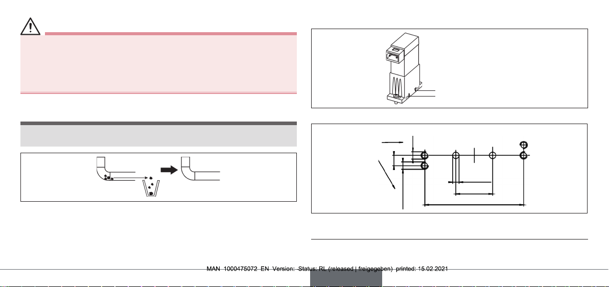
▶Do not operate the device without suitable ltration of the input
medium.
2.1 Denition of terms
Term Denition for these instructions
Device Micro diaphragm pump Type7604
English

4
Risk of short-circuit
Escape of medium due to leaking ttings.
▶Make sure seals are properly seated.
▶Carefully screw together the micro diaphragm pump and manifold.
General hazardous situations.
Ensure the following to prevent injuries:
▶Observe the general rules of technology.
▶Do not use the device in an area prone to explosion.
▶Use the device only when it is in perfect condition and in accor-
dance with the operating instructions.
▶Secure the device or system to prevent unintentional activation.
▶After an interruption in the power supply, ensure that the pro-
cess is restarted in a controlled manner.
▶Do not modify the device. The micro pump cannot be dismantled.
▶Do not mechanically load the device.
▶Only trained technicians may perform installation and mainte-
nance work.
▶Install the device according to the regulations applicable in the
respective country.
▶Check the durability of the parts in contact with media before
using aggressive media.
NOTE!
Electrostatically sensitive components / assemblies!
The device contains electronic components that are susceptible
to the eects of electrostatic discharging (ESD). Components are
at risk if they come into contact with electrostatically charged
persons or objects. In the worst-case scenario, they will be
destroyed immediately or will fail after start-up.
▶Observe the requirements for minimizing or avoiding the pos-
sibility of damage caused by sudden electrostatic discharge in
accordance with EN61340-5-1.
▶Do not touch electronic components while the supply voltage is
switched on!
English

5
4 PRODUCT DESCRIPTION
Micro diaphragm pump Type7604 functions on the basis of the
function principle of a self-priming diaphragm pump. It is suitable
for the continuous conveyance of small quantities of aggressive,
inorganic and biological materials.
Integrated impulse generator
The micro diaphragm pump can optionally be equipped with an
integrated impulse generator. The impulse generator is integrated
into the cover of the device. The desired frequency can be set with
a rotary potentiometer.
4.1 Conformity
The device conforms to the EU directives as per the EU Declaration
of Conformity.
4.2 Standards
The applied standards as used to verify compliance with the Direc-
tives can be found in the EU type examination certicate and/or the
EU Declaration of Conformity.
5 TECHNICAL DATA
5.1 Operating conditions
NOTE!
Malfunction
▶Do not use Type 7604 outdoors without the appropriate hous-
ing and avoid heat sources that may cause the permissible
temperature range to be exceeded.
The conveyance rate of the micro diaphragm pump depends on:
• the viscosity of the medium being conveyed,
• the ow resistance values in front of and behind the pump
(e.g. piping, height dierence),
• the frequency of the supply voltage.
• the temperature
Ambient temperature +10 to +55°C
Medium temperature +10 to +60°C
Degree of protection IP40 (IP30 for rectangular plug Type2505)
Installation position arbitrary, preferably with ange facing
downwards.
English

6
5.1.1 Electrical data
Electrical connection Rectangular plug Type2505, stranded wire
Operating voltage 12/24VDC
Voltage tolerance ±10%
Power consumption 1.5W
5.2 Type label (example)
7604 FFKM PK
24V DC 1,5W
>4,5 ml/min
@35 Hz W18MA
Made in Germany
00156992
1
2
3
4
5
Fig. 1: Location and description of the type label
Item Text Description
1
7604 Device type
FFKM Seal material
PK Body material
224VDC Voltage (direct current, 10% residual ripple)
1.5W Power
Item Text Description
3>4.5ml/min Flow rate (duty cycle 50:50)
4@35 Hz Frequency
W18MA Manufacture code (encrypted)
500156992 Identication number of the device
6 INSTALLATION
CAUTION!
Risk of injury due to high pressure and escaping medium.
▶Before working on the device or system, switch o the pressure.
Exhaust or empty the lines.
Risk of injury due to electric shock.
▶Before working on the device or system, switch o the power
supply. Secure against reactivation.
▶Observe the applicable accident prevention and safety regula-
tions for electrical devices.
English

7
WARNING!
Risk of injury due to improper installation
▶Only trained technicians may perform installation work.
▶Only carry out installations with suitable tools.
▶Secure the system against unintentional activation. Following
installation, ensure a controlled restart.
6.1 Preparatory work
NOTE!
Particles in the medium can lead to impaired function and device
failure. Media that tend to crystallise are also critical.
Fig. 2: Cleaning the connection line
→Clean contaminants from the connection line.
→Install the lter upstream.
Pore size max. 20µm
6.2 Fluidic connection
Outlet
Input
Fig. 3: Fluidic connection
Alternatively
2.25
M1.61)
M1.61)
Ø1.42)
8
21.5
Fig. 4: Flange prole for manifold (mm)
1) at least 5mm deep
2) maximum
English

8
6.3 Fluidic installation
Insert
seal Screw on
pump
Fig. 5: Installation for ange design (F05)
Attach
hose
Fig. 6: Installation for hose connection
Establish hose
connection
Fig. 7: Installation for UNF design (UNFB)
→Install hose connection as shown in the image.
Ferrule
Fitting
Hose
Fig. 8: Structure UNF ¼-28 for uidic connection
English

9
7 ELECTRICAL CONNECTION
7.1 Standard device (duty cycle 1:1)
Rectangular plug 2 stranded wire
Fig. 9: Connection variants
7.2 Device with integrated impulse generator
(optional)
Rotary potentiometer
Polarity
Fig. 10: Connecting a device with integrated impulse generator (electronic)
For these devices, the polarity of the electrical port is specied on
the device cover.
→Note polarity!
The service life of the potentiometer is limited.
The number of rotations is limited to 20, after which a stable fre-
quency of the electronics assembly can no longer be guaranteed.
The sticker must be removed in order to change the frequency with
the rotary potentiometer.
8 MAINTENANCE, TROUBLESHOOTING
CAUTION!
Risk of injury due to high pressure and escaping medium.
▶Before working on the device or system, switch o the pressure.
Exhaust or empty the lines.
Risk of injury due to electric shock.
▶Before working on the device or system, switch o the power
supply. Secure against reactivation.
▶Observe the applicable accident prevention and safety regula-
tions for electrical devices.
English

10
WARNING!
Risk of injury due to improper maintenance work!
▶Only trained technicians may perform maintenance work.
▶Secure the system against unintentional activation.
▶Ensure a controlled restart after maintenance is completed.
8.1 Malfunctions
In case of malfunctions:
→check voltage, frequency and duty cycle.
→Check ow rate of connection lines (too much counter-pressure
at outlet or too much negative pressure at input).
→Check connection lines for contamination.
→Check lter for contamination.
Fig. 11: Cleaning the connection line.
9 ACCESSORIES
For accessories, see data sheet.
10 TRANSPORTATION, STORAGE,
DISPOSAL
NOTE!
Damage in transit due to inadequately protected devices.
▶Protect the device against moisture and dirt in shock-resistant
packaging during transportation.
▶Observe permitted storage temperature.
Incorrect storage may damage the device.
▶Store the device in a dry and dust-free location.
Permitted storage temperature: +10 to +55°C.
Damage to the environment caused by device parts contami-
nated with media.
▶Dispose of the device and packaging in an environmentally
friendly manner.
▶Observe applicable disposal and environmental regulations
▶Observe national waste disposal regulations.
English

www.burkert.com
International address
www.burkert.com
Manuals and data sheets on the Internet: www.burkert.com
Bedienungsanleitungen und Datenblätter im Internet: www.buerkert.de
Manuels d'utilisation et fiches techniques sur Internet : www.burkert.fr
© Bürkert Werke GmbH & Co. KG, 2021
Operating Instructions 2102/08_EU-en_00804583 / Original DE
Bürkert Fluid Control Systems
Sales Center
Christian-Bürkert-Str. 13-17
D-74653 Ingelfingen
Tel. + 49 (0) 7940 - 10-91 111
Fax + 49 (0) 7940 - 10-91 448
E-mail: [email protected]
Table of contents
Other Burkert Water Pump manuals
Popular Water Pump manuals by other brands

Thomas
Thomas 008CA13 quick start guide

Pfeiffer Vacuum
Pfeiffer Vacuum HIPACE 450 operating instructions

Pfeiffer Vacuum
Pfeiffer Vacuum adixen ATH 500 M operating instructions

Oase
Oase Aquamax Eco 4000 CWS operating instructions

salmson
salmson SUBSON Premium Installation and starting instructions

Lubeworks
Lubeworks GUL002 manual

GORMAN-RUPP
GORMAN-RUPP 10 SERIES Installation, operation and maintenance manual

Aquascape Pro
Aquascape Pro 7500 Installation & maintenance instructions

Zoeller
Zoeller X611 owner's manual

Sempomp
Sempomp TKF-K Series user manual

DeWalt
DeWalt Graco PowerFill 3.5 Standard 26B417 Operation, parts

TOHATSU
TOHATSU VC85BS Quick start up guide