Burkert 2031 User manual

Operating Instructions
Bedienungsanleitung
Manuel d‘utilisation
Type 2030, 2031, 2031 K, 2032, 2033, 2037
Piston operated diaphragm valve,
Actuator sizes 175 and 225 mm, Diameter DN65 - DN100
Kolbengesteuerte Membranventile,
Antriebsgrößen 175 und 225 mm, Nennweiten DN65 - DN100
Vannes à membrane commandée par piston, Tailles
de mécanisme 175 et 225 mm, Piston section nominale DN65 - DN100

We reserve the right to make technical changes without notice.
Technische Änderungen vorbehalten.
Sous réserve de modifications techniques.
© Bürkert Werke GmbH & Co. KG, 2000 - 2018
Operating Instructions 1805/11_EU-EN_00803968 / Original DE

3
8 INSTALLATION ............................................................................................15
8.1 Safety instructions ...................................................................15
8.2 Before installation ....................................................................15
8.3 Installation .................................................................................18
8.4 Disassembly..............................................................................20
9 ELECTRICAL CONNECTION ................................................................21
10 MAINTENANCE, CLEANING ................................................................21
10.1 Safety instructions ...................................................................21
10.2 Maintenance Work ..................................................................21
11 REPAIRS.........................................................................................................22
11.1 Safety instructions ...................................................................22
11.2 Replacing the diaphragm ......................................................23
12 MALFUNCTIONS ........................................................................................25
13 SPARE PARTS.............................................................................................26
13.1 Order table ................................................................................27
14 PACKAGING AND TRANSPORT ........................................................27
15 STORAGE ......................................................................................................28
16 DISPOSAL .....................................................................................................28
Piston operated diaphragm valves type 2030, 2031, 2031 K, 2032, 2033, 2037
1 OPERATING INSTRUCTIONS ................................................................4
1.1 Definition of the Term “Device”...............................................4
1.2 Symbols .......................................................................................4
2 AUTHORIZED USE ......................................................................................5
2.1 Restrictions .................................................................................5
3 BASIC SAFETY INSTRUCTIONS ..........................................................6
4 GENERAL INFORMATION ........................................................................7
4.1 Contact Addresses ...................................................................7
4.2 Warranty ......................................................................................7
4.3 Information on the Internet ......................................................7
5 SYSTEM DESCRIPTION ............................................................................7
5.1 General Description ..................................................................7
5.2 Intended Application Area .......................................................7
5.3 Conformity ...................................................................................7
5.4 Standards .................................................................................... 7
6 TECHNICAL DATA ........................................................................................8
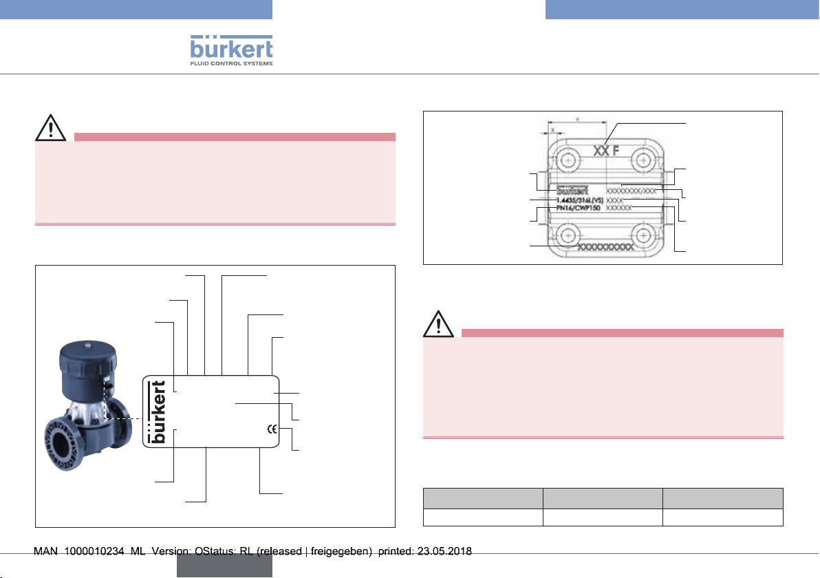
6.1 Inscription on the type label ....................................................8
6.2 Labeling of the forged bodies ................................................ 8
6.3 Operating Conditions ...............................................................8
6.4 General Technical Data..........................................................12
7 STRUCTURE AND FUNCTION............................................................12
7.1 Structure ....................................................................................12
7.2 Function .....................................................................................14
english
Type 2030, 2031, 2031 K, 2032,
2033, 2037

4
Operating Instructions
1 OPERATING INSTRUCTIONS
The operating instructions describe the entire life cycle of the device.
Keep these instructions in a location which is easily accessible to
every user and make these instructions available to every new owner
of the device.
WARNING!
The operating instructions contain important safety
information!
Failure to observe these instructions may result in hazardous
situations.
▶The operating instructions must be read and understood.
1.1 Definition of the Term “Device”
In these instructions, the term “device” always refers to the
diaphragm valves of Types 2030, 2031, 2031 K, 2032, 2033, 2037.
1.2 Symbols
DANGER!
Warns of an immediate danger!
▶Failure to observe the warning may result in a fatal or serious
injury.
WARNING!
Warns of a potentially dangerous situation!
▶Failure to observe the warning may result in serious injuries or
death.
CAUTION!
Warns of a possible danger!
▶Failure to observe this warning may result in a medium or minor
injury.
NOTE!
Warns of damage to property!
▶Failure to observe the warning may result in damage to the
device or the equipment.
Indicates important additional information, tips and
recommendations.
Refers to information in these operating instructions or in
other documentation.
→designates a procedure which you must carry out.
english
Type 2030, 2031, 2031 K, 2032,
2033, 2037

5
Authorized Use
2 AUTHORIZED USE
Non-authorized use of the devices may be dangerous to
people, nearby equipment and the environment.
▶The diaphragm valves of Types 2030, 2031, 2031 K, 2032, 2033
and 2037 are designed for the control of contaminated, ultra-pure
or sterile media, as well as for abrasive or aggressive media (also
with higher viscosity).
▶The devices may be used only for media which do not attack
the body and seal materials (see type label). Information on the
resistance of materials to the media is available from your Bürkert
sales office or on the Internet at: www.burkert.com.
▶During use observe the authorized data, the operating condi-
tions and conditions of use specified in the contract documents
and operating instructions. These are described in the chapter
“5 System Description” and “6 Technical Data”.
▶The device may be used only in conjunction with third-party
devices and components recommended and authorized by
Bürkert.
▶Correct transportation, correct storage and installation and
careful use and maintenance are essential for reliable and fault-
less operation.
▶Use the device only as intended.
2.1 Restrictions
If exporting the system/device, observe any existing restrictions.
2.1.1 Explosion Protection Approval
The explosion protection approval is only valid if you use the
modules and components authorized by Bürkert, as described in
these operating instructions.
If you make unauthorized changes to the system, the modules or
components, the explosion protection approval will also be terminated.
english
Type 2030, 2031, 2031 K, 2032,
2033, 2037

6
Basic Safety Instructions
3 BASIC SAFETY
INSTRUCTIONS
These safety instructions do not make allowance for any:
• Contingencies and events which may arise during the installation,
operation and maintenance of the devices.
• Local safety regulations – the operator is responsible for observing
these regulations, also with reference to the installation personnel.
DANGER!
Danger – high pressure!
▶Before loosening the lines and valves, turn off the pressure and
vent the lines.
Risk of electric shock!
▶Before reaching into the device or the equipment, switch off the
power supply and secure to prevent reactivation!
▶Observe applicable accident prevention and safety regulations
for electrical equipment!
WARNING!
Danger of bursting from overpressure!
▶Observe the specifications on the type label for max. control
and medium pressure.
▶Observe permitted medium temperature.
CAUTION!
Risk of burns/risk of fire if used continuously through hot
device surface!
▶Keep the device away from highly flammable substances and media
and do not touch with bare hands.
General hazardous situations.
To prevent injury, ensure that:
▶The system cannot be activated unintentionally.
▶Installation and repair work may be carried out by authorized
technicians only and with the appropriate tools.
▶After an interruption in the power supply or pneumatic supply,
ensure that the process is restarted in a defined or controlled
manner.
▶The device may be operated only when in perfect condition and
in consideration of the operating instructions.
▶The general rules of technology apply to application planning
and operation of the device.
▶Do not put any loads on the body (e.g. by placing objects on it or
standing on it).
▶Do not make any external modifications to the device bodies. Do
not paint the body parts or screws.
english
Type 2030, 2031, 2031 K, 2032,
2033, 2037

7
General Information
4 GENERAL INFORMATION
4.1 Contact Addresses
Germany
Bürkert Fluid Control Systems
Sales Center
Chr.-Bürkert-Str. 13-17
D-74653 Ingelfingen
Tel. + 49 (0) 7940 - 10 91 111
Fax + 49 (0) 7940 - 10 91 448
E-mail: [email protected]
International
Contact addresses can be found on the final pages of the printed
operating instructions.
And also on the Internet at: www.burkert.com
4.2 Warranty
The warranty is only valid if the device is used as intended in accordance
with the specified application conditions.
4.3 Information on the Internet
The operating instructions and data sheets for Types 2030, 2031,
2031 K, 2032, 2033 and 2037 can be found on the Internet at:
www.buerkert.com
5 SYSTEM DESCRIPTION
5.1 General Description
The Types 2030, 2031, 2031 K, 2032, 2033 and 2037 are an externally
controlled diaphragm valve with piston drive and diaphragm seal. The
valve is self-draining in the appropriate installation position.
5.2 Intended Application Area
The diaphragm valve of Type 2030 is designed for the control of
contaminated and aggressive media. The valves of Type 2031, 2031
K, 2032, 2033 and 2037 can be used even for ultra-pure or sterile
media with a higher viscosity. The valves may only control media
which do not attack the body and seal materials (see type label).
Information on the resistance of materials to the media is available
from your Bürkert sales office.
5.3 Conformity
Type 2030, 2031, 2031 K, 2032, 2033 and 2037 conforms with the
EC Directives according to the EC Declaration of Conformity.
5.4 Standards
The applied standards, which verify conformity with the EC Direc-
tives, can be found on the EC-Type Examination Certificate and / or
the EC Declaration of Conformity.
english
Type 2030, 2031, 2031 K, 2032,
2033, 2037

8
Technical Data
6 TECHNICAL DATA
WARNING!
Risk of injury from high pressure!
Important device-specific technical specifications are indicated on
the type label.
▶Observe permitted pressure range on the type label of the
device.
6.1 Inscription on the type label
Type
Control function Orifice
(Diaphragm size)
Body material
Identification number of
the device
Date of
manufacture
2030 A 65,0 EPDM PV
Made in Germany
00147838
W36LP
Pilot 4,5-6bar
FLNSCH Pmed 10bar
S/N 1060
Seal material
Port connection
Max. medium
pressure
Control pressure
Approval rating
Serial number
Fig. 1: Inscription on the type label (Example)
6.2 Labeling of the forged bodies
Batch number/
manufacturer sign
Company logo
Material
Pressure stage
Production number/
order number
(F-part)
Serial number
Surface quality
code
Customer-specific
text (optional)
Connection orifice
and pipe dimensions
Fig. 2: Labeling of the forged bodies
6.3 Operating Conditions
WARNING!
Danger of bursting from overpressure!
If the device ruptures, the medium may cause injuries, chemical
burns or scalds!
▶Do not exceed the maximum control and medium pressure.
Observe specifications on the type label!
▶Observe permitted ambient and media temperature.
6.3.1 Allowable Temperatures
Ambient temperature for actuators:
Material Size ø Temperature
PA 175 mm / 225 mm -10 ... +50 °C
Tab. 1: Ambient temperature for actuators
english
Type 2030, 2031, 2031 K, 2032,
2033, 2037

9
Technical Data
Maximum permitted medium pressure for control function A
The values apply to body made of:
• Plastic,
• VA forged steel and VA precision casting, VA block material as well
as VA tube-formed body with socket, DIN welding neck flange and
welded connection in accordance with EN ISO 1127 (ISO 4200).
Orifice
(Diaphragm
size)
DN [mm]
Actuator
size ø
[mm]
Max. sealed medium pressure [bar]
Pressure on one
side
Pressure on both
sides
EPDM/
FKM
PTFE EPDM/
FKM
PTFE
65 175 8.0 5.0 5.0 4.5
80 175 5.0 4.5 2.5 2.0
225 10.0 10.0 6.0 4.5
100 225 8.0 4.0 3.5 1.5
Tab. 4: Maximum permitted medium pressure CFA
Medium temperature for body:
Body material Temperature
Stainless steel -10 ... +140 °C
PVC (see PT-graph) -10 ... +60 °C
PVDF (see PT-graph) -10 ... +120 °C
PP (see PT-graph) -10 ... +80 °C
Tab. 2: Medium temperature for body
Medium temperature for diaphragms:
Material Temperature Remarks
EPDM / PTFE -10 ... +130 °C Steam sterilization up to +150 °C
FKM -5 ... +130 °C Dry up to +150 °C
Otherwise only briefly up to +150 °C
Tab. 3: Medium temperature for diaphragms
6.3.2 Maximum permitted medium pressure
Permitted medium pressure depending on the medium temperature.
DN 65 - 100
10
8
6
4
2
20 40 60 80 100 120 140
PVC
PVDF
PP
Medium pressure [bar]
Temperature [°C]:
Fig. 3: Graph of medium pressure / Medium temperature
english
Type 2030, 2031, 2031 K, 2032,
2033, 2037

10
Technical Data
6.3.3 Control Pressure
WARNING!
Danger of bursting from overpressure!
If the device explodes, there is a risk of serious injury, chemical
burns, scalding!
▶Do not exceed the maximum control and medium pressure.
Observe specifications on the type label!
NOTE!
Malfunction due to incorrect control pressure!
The specifications on the type label apply to valves with reduced
spring force (i.e. with lower control pressure). If you are unsure,
please contact your Bürkert sales office.
Permitted control pressure*
Orifice
(Diaphragm size)
DN [mm]
Actuator
size
ø mm
Min. control
pressure
[bar]
Max. control
pressure
[bar]
65 175 2 6
80 175 2 6
80 225 2 6
100 225 2 6
Tab. 5: Permitted control pressure
* Observe the permitted pressure range according to the
type label!
Control pressure for control function A
Orifice
(Diaphragm
size)
DN [mm]
Actuator size
[mm]
Control pressure [bar]
for medium pressure
0 bar maximum
65 175 64.5
80 175 65.0
80 225 65.0
100 225 65.0
Tab. 6: Control pressure CFA
6.3.4 Minimum Control Pressure
Required minimum control pressure depending on medium
pressure
The values apply to body made of:
• Plastic
• All models with VA forged steel, VA precision casting and VA
block material
• VA tube-formed body with socket, DIN welding neck flange and
weld-on ends in accordance with EN ISO 1127 (ISO 4200)
english
Type 2030, 2031, 2031 K, 2032,
2033, 2037

11
Technical Data
Control function B (CFB)
NOTE!
Important for the service life of the diaphragm!
• Do not select control pressure higher than required.
DN 65 / Ø 125
DN 65 / Ø 175
DN 80 / Ø 175
DN 100 / Ø 175
Elastomer diaphragm
Diaphragm size / Actuator diameter
Control pressure [bar]
Medium pressure [bar]
10
9
8
7
6
5
4
3
2
1
00 1.0 2.0 3.0 4.0 5.0 6.0 7.0
Fig. 4: Control function B - Elastomer diaphragm
DN 65 / Ø 125
DN 65 / Ø 175
DN 80 / Ø 175
DN 100 / Ø 175
PTFE - Diaphragm
Diaphragm size / Actuator diameter
Control pressure [bar]
Medium pressure [bar]
10
9
8
7
6
5
4
3
2
1
00 1.0 2.0 3.0 4.0 5.0 6.0 7.0 8.0
Fig. 5: Control function B - PTFE diaphragm
Control function I
DN 65 / Ø 125
DN 65 / Ø 175
DN 80 / Ø 175
DN 100 / Ø 175
Elastomer diaphragm
Diaphragm size / Actuator diameter
Control pressure [bar]
Medium pressure [bar]
10
9
8
7
6
5
4
3
2
1
00 1.0 2.0 3.0 4.0 5.0 6.0
Fig. 6: Control function I - Elastomer diaphragm
DN 65 / Ø 125
DN 65 / Ø 175
DN 80 / Ø 175
DN 100 / Ø 175
PTFE - Diaphragm
Diaphragm size / Actuator diameter
Control pressure [bar]
Medium pressure [bar]
10
9
8
7
6
5
4
3
2
1
00 1.0 2.0 3.0 4.0 5.0 6.0 7.0
Fig. 7: Control function I - PTFE Diaphragm
english
Type 2030, 2031, 2031 K, 2032,
2033, 2037

12
Structure and Function
6.4 General Technical Data
Materials
Body
Type 2030 PP, PVC, PVDF
Type 2031 Stainless steel precision casting (VG),
Forged steel (VS)
Type 2031 K Stainless steel tubular body (VA)
Type 2032, 2033, 2037 Stainless steel - block material
Actuator PA
Sealing elements actuator NBR
Diaphragm EPDM, PTFE, FKM
Connections
Control air connection G1/4
Medium connection Welded connection: in accordance with
DIN EN 1127 (ISO 4200), DIN 11850 R2
other connections on request
Media
Control medium neutral gases, air
Flow media Type 2030:
contaminated and aggressive media
Type 2031, 2032, 2033 and 2037:
contaminated, aggressive, ultra-pure, sterile
media and media with higher viscosity
Installation position any position, preferably with the actuator
face up,
Tank bottom valve Type 2033: Actuator to
the bottom
7 STRUCTURE AND FUNCTION
7.1 Structure
7.1.1 2/2-way valve type 2030, 2031 and
2031 K
The piston-controlled diaphragm valve consists of a pneumatically
actuated piston actuator and a 2/2-way valve body.
Transparent cap with
position indicator
Actuator body with cover
Upper control air connection
(for CFB and CFI)
Lower control air connection
(for CFA and CFI)
Diaphragm socket
Diaphragm body
Port connection
Fig. 8: Structure and description type 2030
english
Type 2030, 2031, 2031 K, 2032,
2033, 2037

13
Structure and Function
7.1.2 T-valve Type 2032
Transparent cap with
position indicator
Actuator cover
Diaphragm socket
T-valve body
Actuator body
Port connection
Upper control air connection
(for CFB and CFI)
Lower control air connection
(for CFA and CFI)
Fig. 9: Structure and descriptions type 2032
7.1.3 Tank bottom valve type 2033
Transparent cap with position
indicator
Actuator cover
Diaphragm socket
Tank bottom valve with
welding flange
Port connection
Actuator body
Upper control air connection
(for CFB and CFI)
Lower control air connection
(for CFA and CFI)
Fig. 10: Structure and description type 2033
english
Type 2030, 2031, 2031 K, 2032,
2033, 2037

14
Structure and Function
7.1.4 Y-valve type 2037
Transparent cap
with position indicator
Actuator cover
Upper control air connection
(for CFB and CFI)
Lower control air connection
(for CFA and CFI)
Diaphragm socket
Y-valve body
Actuator body
Port connection
Fig. 11: Structure and description type 2037
7.2 Function
Spring force (CFA) or pneumatic control pressure (CFB and CFI) gen-
erates the closing force on the diaphragm pressure piece. The force
is transferred via a spindle which is connected to the actuator piston
and the valve is opened and closed.
7.2.1 Control functions
Control function A (CFA)
Closed by spring force in rest position
A
P
Control function B (CFB)
Opened by spring force in rest position
B
P
Control function I (CFI)
Double-acting actuator without spring
P
A
english
Type 2030, 2031, 2031 K, 2032,
2033, 2037

15
Installation
8 INSTALLATION
8.1 Safety instructions
DANGER!
Risk of injury from high pressure in the equipment!
▶Before loosening the lines and valves, turn off the pressure and
vent the lines.
Risk of injury due to electrical shock!
▶Before reaching into the device or the equipment , switch off the
power supply and secure to prevent reactivation!
▶Observe applicable accident prevention and safety regulations
for electrical equipment!
WARNING!
Risk of injury from improper installation!
▶Installation may be carried out by authorized technicians only
and with the appropriate tools!
Risk of injury from unintentional activation of the system and
an uncontrolled restart!
▶Secure system from unintentional activation.
▶Following assembly, ensure a controlled restart.
8.2 Before installation
• Before connecting the valve, ensure the pipelines are flush.
• The flow direction is optional.
8.2.1 Installation position general
Installation for self-drainage of the body
It is the responsibility of the installer and operator to ensure
self-drainage.
Installation for leakage detection
One of the bores (in the actuator base) for monitoring
leakage must be at the lowest point.
8.2.2 Installation position 2/2-way valve
• The piston-controlled diaphragm valve can be installed in any
installation position, preferably with the actuator face up.
To ensure self-drainage:
→Install body inclined by angle α = 10° bis 40° to the horizontal
(see “Fig. 12”).
→Observe an inclination angle of 1° – 5°. Forged and cast bodies
feature a mark which must face upwards
(12 o‘clock position, see “Fig. 13”).
→One of the bores (in the actuator base) for monitoring leakage
must be at the lowest point.
english
Type 2030, 2031, 2031 K, 2032,
2033, 2037

16
Installation
Angle α: 10° to 40°
Inclination to the
line axis 1° ... 5°
Fig. 12: Installation position for self-drainage of the body
Mark for self-drainage
angle
Fig. 13: Mark for the correct installation position
8.2.3 Installation position of T-valve
Type 2032
For the installation of the T-valves into circular pipelines, we rec-
ommend the following installation positions:
When media is supplied: When media is removed:
Fig. 14: Installation position of type 2032
8.2.4 Installation position of Y-valve
Type 2037
For the installation of the Y-valves into systems, we recommend the
following installation positions:
When media is supplied: When media is removed:
Fig. 15: Installation position of type 2037
english
Type 2030, 2031, 2031 K, 2032,
2033, 2037

17
Installation
8.2.5 Installation of the tank bottom valve
Type 2033
For further information on containers and welding instruc-
tions, please refer to the standard ASME VIII Division I.
It is recommended to weld the valve prior to the container
installation. However, it is possible to weld the valves to ready-
assembled containers.
Prior to welding, please check to ensure that:
• The tank bottom valve does not collide with other equipment compo-
nents and assembly/disassembly of the actuator is always possible.
• A minimal distance between two welding joints three times the
thickness of the container wall is adhered to.
It is recommended to weld the valve in the center of the drain
to ensure optimum draining of the container.
The diameter of the hole in the container and the flange must be equal.
The valve has two welding edges to make welding and positioning of
the valve easier. The length of the welding edges is approximately 3
mm. In case the thickness of the container wall exceeds 3 mm, the
valve must be positioned as shown in “Fig. 16”.
→Prior to welding the valve, grind the outlet wall.
Grinding point
on tank
Fig. 16: Grinding point on tank
Prior to commencing the welding process, check the charge
number indicated on the supplied manufacturer’s certificate
3.1.B.
Procedure:
→Position the flange into the hole so that the flange surface is
tangent to the drain surface.
→Tack 4 welding points and check the position of the valve.
→Weld the valve evenly to the inside and outside of the container,
with gas being supplied and using welding material compatible
with the valve’s stainless steel 316L (DIN 1.4435).
→Allow the welds to cool down before burnishing and cleaning
them according to the applicable specifications.
These instructions assist in the installation of the tank bottom valves
and allow the prevention of deformation and softening within the
containers.
english
Type 2030, 2031, 2031 K, 2032,
2033, 2037

18
Installation
Please observe the applicable laws and regulations of the
respective country with regard to the qualification of welders
and the execution of welding work.
8.2.6 Preparatory Work
→Clean pipelines (sealing material, swarf, etc.).
→Support and align pipelines.
Devices with welded body:
Before welding the body, the actuator and the diaphragm
must be removed.
8.3 Installation
If used in an aggressive environment, we recommend con-
veying all free pneumatic connections into a neutral atmo-
sphere with the aid of a pneumatic hose.
WARNING!
Risk of injury from improper installation!
Non-observance of the tightening torque is dangerous as the
device may be damaged.
▶Observe tightening torque during installation (see “Tab. 7: Tight-
ening torques for diaphragms”).
8.3.1 Devices with welded body
NOTE!
To prevent damage!
Before welding the body (only device with welded body), the
actuator and the diaphragm must be removed.
Remove actuator and diaphragm from the body:
Procedure for control function A
→Pressurize lower control air connection with compressed air
(value as indicated on the type label) (see “Fig. 17”).
This is required to detach the diaphragm without damage from
the body.
→Loosen fastening screws crosswise and remove actuator
together with diaphragm from the body.
→Weld body into the pipeline.
Procedure for control functions B and I
→Loosen fastening screws crosswise and remove actuator
together with diaphragm from the body.
→Weld body into the pipeline.
Mount actuator and diaphragm on the body:
→After welding in the body, smooth the body surface by grinding if
required.
→Carefully clean the body.
english
Type 2030, 2031, 2031 K, 2032,
2033, 2037

19
Installation
Procedure for control function A
→Pressurize lower control air connection with compressed air
(value as indicated on the type label) (see “Fig. 17”).
→Place actuator on the body.
→Lightly cross-tighten the body screws until the diaphragm is
between the body and actuator.
Do not tighten the screws yet.
→Actuate the diaphragm valve twice to position the diaphragm
correctly.
→Without applying pressure, tighten the body screws to the permitted
tightening torque (see “Tab. 7”).
→Pressurize lower control air connection with compressed air (value
as indicated on the type label).
→Check the tightening torque of the screws again.
Procedure for actuator with control functions B and I:
→Place actuator on the body.
→Lightly cross-tighten the body screws without pressurization until
the diaphragm is between the body and actuator.
Do not tighten the screws yet.
→Pressurize upper control air connection with compressed air (value
as indicated on the type label) (see “Fig. 17”).
→Actuate the diaphragm valve twice.
→Tighten the body screws to the permitted tightening torque (see
“Tab. 7”)
Upper control air connection
(for CFB and CFI)
Lower control air connection
(for SFA and SFI)
Fig. 17: Control air connection
Tightening torques for plastic body, VA tubular body (VA) and
forged body
Orifice
(Diaphragm size)
DN [mm]
Tightening torque [Nm]
(values for guidance)
EPDM/FKM PTFE / advanced PTFE /
laminated advanced PTFE
65 20 30
80 30 40
100 40 50
Tab. 7: Tightening torques for diaphragms
english
Type 2030, 2031, 2031 K, 2032,
2033, 2037

20
Installation
Stainless Steel Insert (only for units without diaphragm and
casing)
If you have ordered and received a unit without diaphragm and casing,
a stainless steel insert (Id.-Nr. 648 864) will have been included with it.
Use of an EPDM / FKM diaphragm:
→When assembling a unit with an
elastomer diaphragm (EPDM/FKM),
lay the stainless steel insert into the
groove in the pressure component.
Use of a PTFE - Diaphragm:
→When using a PTFE diaphragm, the
insert is not required.
Insert
8.3.2 Connection of the control medium
Control function A:
→Connect control medium to lower connection.
Control function B:
→Connect control medium to upper connection.
Control function I:
→Connect control medium to upper and lower connections.
(see “Fig. 18”)
→Pressure on the upper connection closes the valve.
→Pressure on the lower connection opens the valve.
Upper control air connection
(for CFB and CFI)
Lower control air connection
(for CFA and CFI)
Fig. 18: Pneumatic connection
Control air hose:
Control air hoses of sizes 6/4 mm or 1/4“ can be used.
8.4 Disassembly
DANGER!
Risk of injury from discharge of medium (acid, alkali, hot
media)!
It is dangerous to remove the device under pressure due to the
sudden release of pressure or discharge of medium.
▶Before removing a device, switch off the pressure and vent the
lines.
▶Completely drain the lines.
Replacement of the diaphragm is described in the chapter
entitled “11 Repairs”.
english
Type 2030, 2031, 2031 K, 2032,
2033, 2037
Other manuals for 2031
3
This manual suits for next models
5
Table of contents
Languages:
Other Burkert Water Pump manuals
Popular Water Pump manuals by other brands

teel
teel 4RJ45 Operating instructions & parts manual

SKC
SKC 224-PCXR8M operating instructions

Oase
Oase AquaMax Eco Twin 20000 operating instructions

North Star
North Star S 10633 owner's manual

Liberty Pumps
Liberty Pumps LGV Series installation manual

CALPAK
CALPAK FlowSol S Manual for the specialised craftsman

Clarke
Clarke PSV7A Operation & maintenance instructions

Graco
Graco FIRE-BALL Series Instructions and parts

Toyo
Toyo DBH Series Installation, operation and maintenance manual

superior pump
superior pump 94505 owner's manual

IVT
IVT VP-280 manual

KNF
KNF OEM TRANSLATION OF ORIGINAL OPERATING AND INSTALLATION INSTRUCTIONS