Bushman M5067 Use and care manual

COIL LIFTER
M5067 & MR5067
Operation Safety & Maintenance Manual

REVIEWING THE MARKINGS
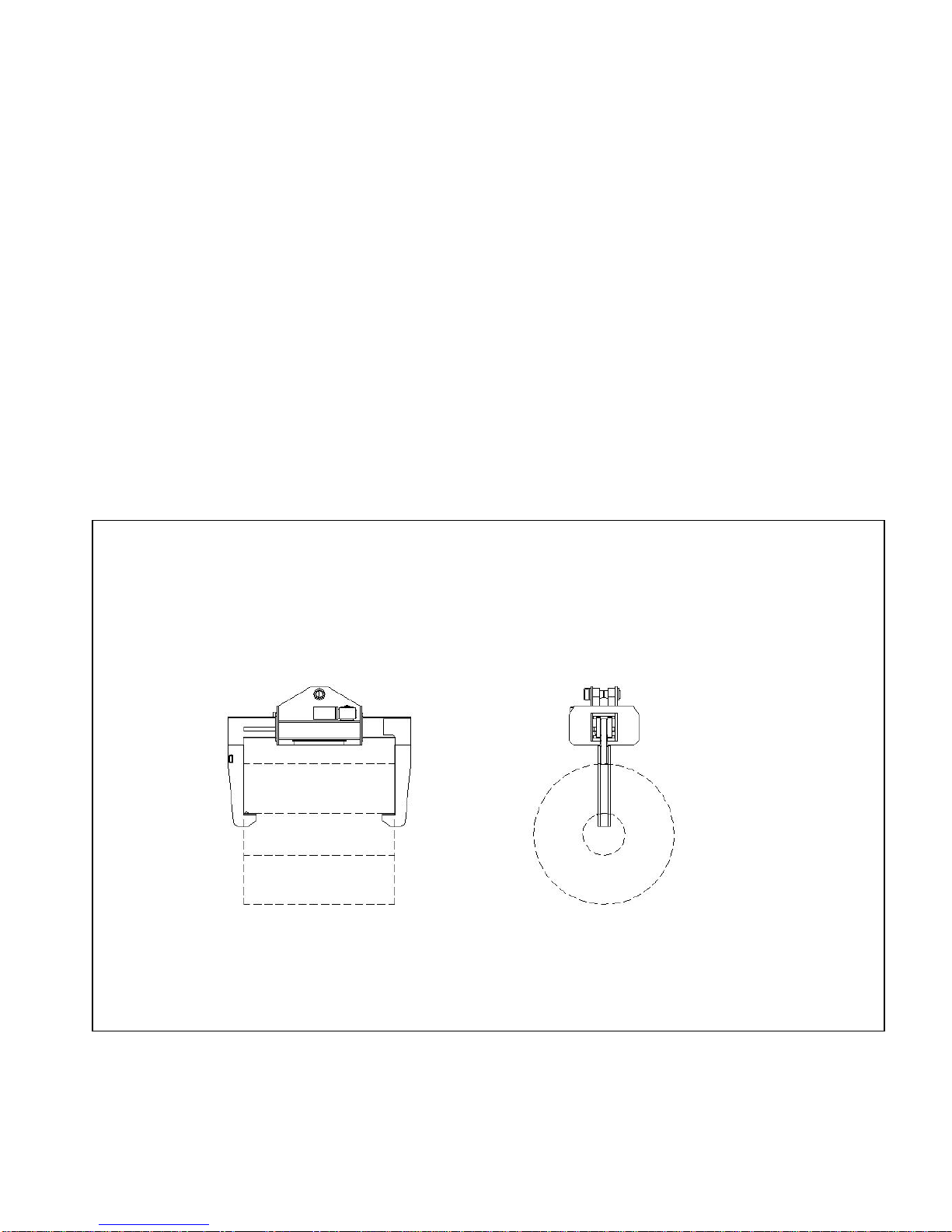
The capacity of each coil lifter is listed on the identification plate which is located on the inside face of
the frame.
The live load plus the weight of the lifter (also listed on the identification plate) cannot exceed the
rated capacity of the crane. To prevent accidents to personnel and equipment, never exceed the
maximum load capacity.
Operators must be familiar with all safety and identification decals and maintain them in a clean and
legible condition. If new decals are required, call the factory for free replacements. Refer to the
Identification and Safety Standards, page for markings
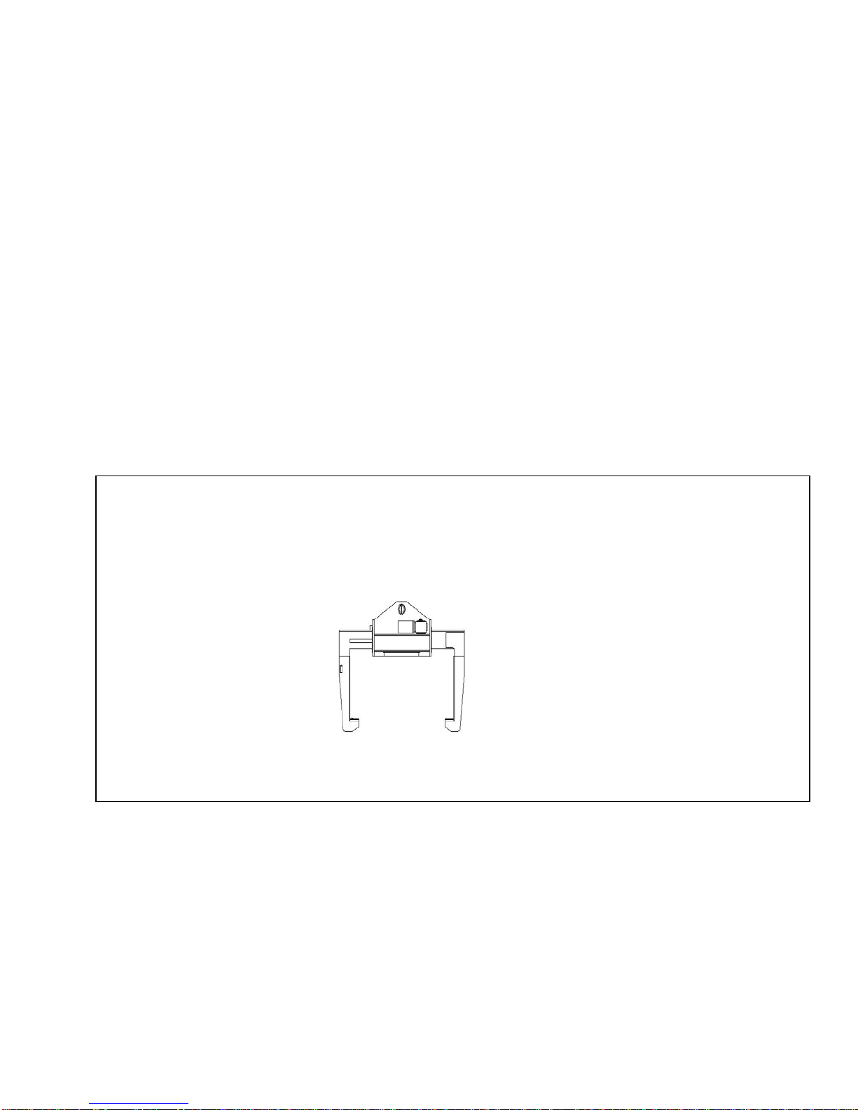
BECOMING FAMILIAR WITH THE LIFTER
Before operating the coil lifter, review this safety manual.
The lifter is shipped completely assembled except for electrical connections. Take particular note of
all safety warnings and safety decals before making electrical connections.
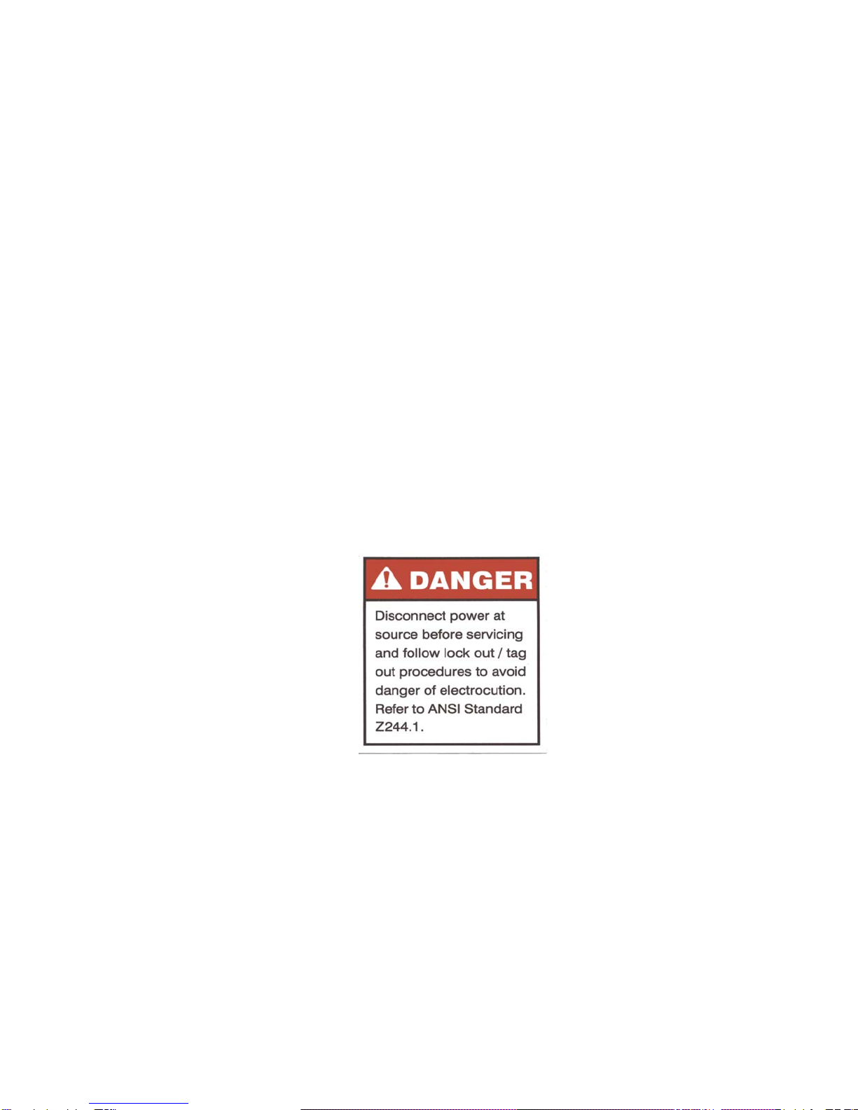
If electrical controls are furnished with the lifter, refer to the wiring diagram provided. Always
disconnect power at source before servicing the lifter. When connecting lifter to power supply, be sure
to follow approved lockout/tagout procedures as outlined in ANSI Z244.1. Only qualified personnel
should install and/or service this lifter.
Coil lifters are furnished with an adjustable clutch on the reducer output shaft. Before putting the
lifter into service, test it with a test load and adjust the clutch with the spanner wrench to eliminate
excess slippage. Caution: Do not over tighten the clutch. This may result in damage to the drive
components. Refer to clutch adjustment instructions in this manual.
Before operating lifter, replace reducer solid pipe plugs with vent plugs provided and check the oil level
in both reducers. Use lubricant specified by reducer manufacturer.
Warning: Coil lifters are large and top-heavy; they can cause personal injury or property damage if
they fall over. When not in use each coil lifter should be stored on a stand designed for its specific
size and weight by the factory or a qualified engineer.

OPERATING INSTRUCTIONS
The electrical control system integrated with the lifter must be equipped with an open and close
function. "Open" increases the gap between the lifting legs; "close" decreases the gap between the
lifting legs.
To operate the lifter, open the legs until the lifter is wider than the coil to be handled. Move the lifter
so that it is centered over the coil, and then lower it until the lifting shoes are centered on the coil ID.
Close the lifter until the legs engage both sides of the coil. Note: It may be necessary to re-center the
lifter over the coil to ensure proper engagement.
Slowly raise the coil grab until the coil begins to rise. Before continuing the lift, inspect the lifter and
coil to be sure the load is properly engaged. Make adjustments if necessary. Recheck the load path
and then proceed with the lift.
Transport the coil to its destination. Lower the lifter until the coil contacts the storage surface. Open
the coil lifter until the lifting shoes clear the coil. Raise the coil lifter above the coil and proceed to
next lift.
When lifting is complete, return the lifter to its properly designed storage stand. Prevent personal
injury by keeping hands and feet clear as the lifter is lowered into the stand.
When using lifter follow all safety instructions and warnings.

LIFTING CONSIDERATIONS
oPlan the lift before engaging the load.
oUse the lifter for its designated purpose only.
oNever ride or allow riders on the lifter.
oDo not lift loads beyond the lifter's rated capacity.
oBefore moving a load, be sure the path of the load is clear of obstructions and personnel. Take
instructions only from the person designated to give signals.
oMake sure everyone is in a safe place before moving the load. This includes the operator who should
remain at a safe distance and should not push or touch the load.
oAlign the lifter perpendicular to the path of travel before attempting to move the load.
oRaise the lifter only as high as necessary to clear obstacles.
oWarning: Never move loads over people, or let loads bump or catch on any obstruction. Injury or
damage may result.
oKeep the load level. Avoid sudden starts and stops that may cause the load to swing like a pendulum
and strike an object or person.
oDo not leave a suspended load unattended.
Safest Path of Travel
NO YES

INSPECTION
Safe operating practices require scheduled inspections to ensure that the coil lifter is maintained in a
safe operating condition. An individual record of inspections and repairs, such as the one on the back
cover of this booklet, should be maintained for each lifter.
At the beginning of each shift, inspect the unit to be sure it is in safe operating condition. Be sure all
capacity, weight and safety markings are in place and legible.
Every two months the coil lifter should be visually inspected in the areas indicated. Lifters showing
excessive wear or damage should be removed from service.
Coil lifters are furnished with various types of bails that should be inspected for wear. Call for repairs
or replacement parts if load-bearing sections show wear in excess of 20% of the original. See certified
drawing for original bail dimensions. Do not attempt to repair bails without consulting the factory.
Clutch Adjustment Instructions
Critical inspection areas
Bail Assembly
Area
Knee Knee
Area Area
Support Shoe
Area

1) Prior to clutch adjustment loosen locking set screw located above the adjustment nut in the side of the
clutch housing. Note: Set screw must be loosened prior to making any clutch adjustment.
2) Using Spanner wrench provided tighten locking nut clockwise to prevent clutch slippage then position
nut so that one of the vertical grooves aligns with one of set screw holes. Tighten set screw. Note: Do
not tighten set screw if it is not aligned with nut groove or thread damage may occur.
3) Note: During the initial break in period re-adjustment of clutch may be necessary.
Warning!
Do not over tighten the clutch. This may result in damage to dive components.

Lubrication & Maintenance instructions
1) Always disconnect power at source before servicing unit.
2) Coat teeth of rack, pinion, and slewing ring gear for models with rotation (MR models), drive every two
months. Use Jet Lube Gear Guard, open gear lubricant.
3) Lubricate slides and slide ways every two months using STL Compound Corporation “SAF-T-EZE” (anti
seize regular). High duty cycles may require more frequent lubrication.
4) Lubricate roller chains and sprockets as required depending on the duty cycle.
5) Check rack pinions and roller chains for wear every six months. Replace if necessary.
6) Check entire unit for wear, loose bolts, etc., every two months.
7) Check oil level in reducer or gear motors every six months. If low, fill according to manufacturer’s
recommendation.
8) Lubricate flange bearings with EP#2 grease every six months.
9) Check bail pin/area for wear every two months. Bail should be repaired or pin replaced if it is worn more
than 20% of its original size.
Note: When ordering replacement parts or inquiring about the lifter, please refer to serial number
shown on the identification tag on lifter.

RECORD OF INSPECTION AND MAINTENANCE
Date
Inspection or
Maintenance Procedure
Findings
Initials
This manual suits for next models
1
Table of contents
Other Bushman Lifting System manuals