Bolton Tools HP-L4G Instruction manual

HP-L4G


1
HP-L4G

2
* Lift capacity ratings are based on loads equally distributed on all fourarms.
** Lifting and lowering speeds may vary depending on weight ofvehicle.
VERTICAL CLEARANCE
Check the height of the area where the lift is to be installed. Clearance should be calculated based on the
full raised height of the lift.
Failure by purchaser to provide adequate clearance could result in
unsatisfactory lift performance, property damage, or personal injury.
FLOORING
Be certain you have the proper concrete floor to properly handle the loaded lift. Floor should be in
generally good condition with no large cracks, spalling or deterioration.
Minimum requirements for concrete are 4 inches minimum depth, with steel reinforcement, 3500
PSI, cured for 28 days per local commercial practice.
Floor should be level within 3/8 inch over the installation area. No anchors should be installed within 8
inches of any crack, edge, or expansion joint. If these conditions cannot be met, pads can be poured to
accommodate the lift.
Check with local building inspectors and/or permits office for any special instructions or approvals
required for your installation.
Failure by purchaser to provide the recommended mounting
surface could result in unsatisfactory lift performance, property
damage, or personal injury.
ELECTRICAL REQUIREMENTS
For lift installation and operation for single phase units, it is necessary to have a dedicated circuit with a
double pole 25 amp circuit breaker or time delay fuse.
SAFETY NOTICES AND DECALS
For your safety, and the safety of others, read and understand all of the safety notices and decals included
here.
READ ENTIRE MANUAL BEFORE ASSEMBLING, INSTALLING, OPERATING, OR
SERVICING THIS EQUIPMENT.
PROPER MAINTENANCE AND INSPECTION IS NECESSARY FOR SAFE OPERATION.
DO NOT OPERATE A DAMAGED LIFT.

3
Safety decals similar to those shown here are found on a properly installed lift. Be sure that all safety
decals have been correctly installed on the Power Unit reservoir. Verify that all authorized operators
know the location of these decals and fully understand their meaning. Replace worn, faded, or damaged
decals promptly.
Do not attempt to raise a vehicle on the lift until the lift has been
correctly installed and adjusted as described in this manual.
RECEIVING
The shipment should be thoroughly inspected as soon as it is received. The signed bill of lading is
acknowledgement by the carrier of receipt in good condition of shipment covered by our invoice.
If any of the goods called for on this bill of lading are shorted or damaged, do not accept them until the
carrier makes a notation on the freight bill of the shorted or damaged goods. Do this for your own
protection.
NOTIFY our company AT ONCE if any hidden loss or damage is discovered after receipt.
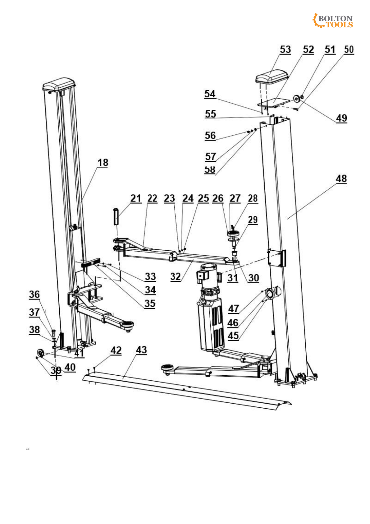
Component Packing List
DESCRIPTION
QTY
DESCRIPTION
QTY
Power Column Ass’y
1
Synchronizer Cable
2
Idler Column Ass’y
1
Hydraulic Hose Pack
1
Floor-Plate Ass’y
1
Power Lock Cover
1
Arm Ass’y
4
Idler Lock Cover
1
Hardware Box
1

4
INSTALLATION
IMPORTANT: Always wear safety glasses while installing lift.
TOOLS (MINIMUM REQUIRED)
a. Banding Cutter
b. Tape measure,
c. Chalk line
d. level
e. adjustable wrench
f. Standard open end wrenches
g. Needle nose pliers
h. Hammer drill with diameter carbide
i. hammer
j. Torque wrench
k. Step ladder
l. Anti-Seize lubricant (for arm pins)
LAYOUT
1. Layout the service bay according to the architect’s plans or owners instructions. Be certain that the
proper conditions exist.
2. Assemble column extension to column using M12×30 Hex bolt. Repeat for opposite columnand
extension.
3. Using the Overall Width(C) as a guideline, chalk two parallel on the concrete floor within 1/8 inch
tolerance.
4. Determine the location of the Column Ass’y on either chalk line and mark the base plate dimension
Overall Width(L) .
Fig 2 –Floor Plan

5
Fig 3
Be sure to stay within a 1/4 inch overall tolerance. This will eliminate any
difficulty in final assembly or possible premature chain wear or
misalignment.
The chalk line layout is very important. If it is not followed accurately problems may arise in final
assembly and operation.
5. Using a lifting device, Erect both column assemblies with the installation lines.
ANCHORING
6. The anchor bolts must be installed at least 8 inches from any crack, edge, or expansion joint.
7. Use a concrete hammer drill with a 5/8 inch carbide bit. Do not use excessively worn bits or bits
which have been incorrectly sharpened. A core bit may be necessary if an obstruction is encountered.
Never substitute with shorter anchor.
8. Vacuum dust from the hole for proper holding power.
9. Shim both columns to plumb using the shims provided. DO NOT shim more than 1/2" at any given
point. Use a level no less than 24” in length to plumb columns.
10. Assemble washer and nut to anchor with nut just below impact section of bolt. Drive anchor into
hole until nut and washer contact base.
11. Tighten power column anchors and recheck column for plumb. Reshim if necessary. Torque to 150
foot pounds to set anchors.
Never remove the lift before the columns Tightened by the anchor bolts.
FLOOR-PLATE
12. Assemble floor-plate ass’y to floor.
SYNCHRONIZER CABLES
13. Manually raise the carriages until each is located on the second lockposition.
14. Route synchronizing cables using Fig 4 and attach ends to carriages’ joining using Fig’s 5.
15. Adjust cable tension by adjusting each cable’s adjustment nuts. The cables should be tight with no
slack. Each cable should be the same tension. Be sure as you are tightening the cables that they have
remained in place over the pulleys. Failure to do this will result in damage to thecable.

6
Fig 4- Cable Routing
over the pulleys.
Fig 5- Attaching Cable
Prior to operation of lift recheck equalizer cables making sure they are not
crossed or routed improperly. Be sure the cables have remained in place
POWER UNIT & HYDRAULIC HOSE
18.Mount Power Unit to power column as shown in Fig 6 The mounting hardware, M8 hex nuts, are pre-
installed on power unit mounting bracket.
19. IMPORTANT –To insure proper hose fitting seal without damage to the fitting follow this
procedure for each hose connection: Screw flared fitting on finger tight. Rotate flared fitting 1 1/2 hex
flats (90 deg.). Back the flared fitting off one full turn. Again tighten flared fitting finger tight, then
rotate flared fitting 1 1/2 hex flats (90 deg).
20. Thread power unit hydraulic hose into elbow on power unit. Route hydraulic hose from Idler column
across floor plate ass’y to the Power Column.(Fig 6)
21. Once the Power Unit is secured, fill reservoir with #10 weight HYDRAULIC OIL ONLY.Care

7
should be taken to keep dirt or other contamination out of oil.
ARM INSTALLATION
22. Lubricate the arm pin or carriage arm pin hole with “anti-seize” and install the arms. Insure that the
arm restraint gears engage and disengage properly. Arm restraints any binding occurs, insure that the
large gear mounted to the arm has been factory installed tight against the arm pin.
FINAL ADJUSTMENTS
23. Lower the lift to the floor and raise the lift approximately onefoot.
24. Start with Idler side first. Slowly and carefully loosen the bleed plug on top of the cylinder just
enough to allow the entrapped air to escape. Repeat for powerside.
25. Energize the power unit and raise 6 inches. Repeat previous step until no air comes out ofcylinder.
26. Pressure test hydraulic system. Energize power unit, raise lift to full rise and continue to run motor
for additional 10 seconds. (NOTE: pressure relief will make a high pitch squeal sound for these 10
seconds.) Check hydraulic system for leaks.
27. Energize power unit again for 10 seconds. With a clean rag, wipe down both cylinder rods. If
lubricant is not wiped clean from the cylinder rod, the cylinder will appear to beleaking.
28. Cycle lift to insure that the latches operate simultaneously. Lower the lift onto the locks and insure
that neither lock will wobble (it is possible for the carriages to appear to be resting on the locks
when actually only one carriage is resting on its lock and the other carriage is being supported by the
synchronizing cable).
29. Lower lift to the floor. Pull and release lock release handle while watching idler column lock. Adjust
threaded sleeve cable adjuster nuts until idler column lock disengages and engages fully. When
properly adjusted, the idler column lock should just come to rest against the back of the column
when engaged and fully out against the tab whendisengaged.
IMPORTANT: IF IDLER SIDE LOCK PAWL DOES NOT FULLY DISENGAGE, DAMAGE
MAY RESULT TO IDLER SIDE CARRIAGE AND OR CABLE SYNCHRONIZING SYSTEM.
30. Tighten and trim wireties.
31. Snap lock cover over each lock assembly.
OPERATION PROCEDURE
SAFETY NOTICES AND DECALS
This product is furnished with graphic safety warning labels, which are reproduced on page 3 of
these instructions. Do not remove or deface these warning labels, or allow them to be removed or
defaced. For your safety, and the safety of others, read and understand all of the safety notices and
decals included.
OWNER/EMPLOYER RESPONSIBILITIES
The Owner/Employer shall insure that lift operators are qualified and that they are trained in the safe
use and operation of the lift using the manufacturer’s operating instructions;, Lifting it Right safety
manual; American National Standard for Automotive Lifts-Safety Requirements for Operation,
Inspection and Maintenance; ALI Uniform Warning Label Decals/Placards; and in case of frame
engaging lifts, Vehicle Lifting Points/Quick Reference Guide for Frame Engaging Lifts.

8
The Owner/Employer shall establish procedures to periodically inspect the lift in accordance with
the lift manufacturer’s instructions, American National Standard for Automotive Lifts-Safety
Requirements for Operation, Inspection and Maintenance; and the employer shall insure that the lift
inspectors are qualified and that they are adequately trained in the inspection of the lift.
The Owner/Employer shall establish procedures to periodically maintain the lift in accordance
with the lift manufacturer’s instructions, American National Standard for Automotive Lifts-Safety
Requirements for Operation, Inspection and Maintanence; and the employer shall insure that the lift
maintenance personnel are qualified and that they are adequately trained in the maintenance of the lift.
The Owner/Employer shall maintain the periodic inspection and maintenance records recommended by
the manufacturer, American National Standard for Automotive Lifts-Safety Requirements for Operation,
Inspection and Maintenance.
LIFTINGA VEHICLE
1) Insure that the lifting arms are parked, out to full drive thruposition.
2) Position the vehicle in the service bay so that the vehicle’s center of gravity is on a line between the
two columns, and so the vehicle is centered between the twocolumns.
DO NOT ATTEMPT TO LIFT THE VEHICLE WITH ONLY TWO ARMS, AS THIS WILL
VOID THE WARRANTY
INSURE THAT THE HIGHEST POINT ON THE VEHICLE WILL CONTACT THE
OVERHEAD LIMIT SWITCH BAR
DO NOT PLACE THE VEHICLE IN THE SERVICE BAY BACKWARDS.
3) Position the arms and adapters so all four pads contact the vehicle simultaneously.
The vehicle should remain level during lifting.
4) Raise the lift until all four wheels are off the ground. Test the stability of the vehicle by attempting
to rock the vehicle. Check adapters for secure contact with vehicle lift points. If the vehicle seems
unstable, lower the lift and readjust the arms. If the vehicle is stable, raise the vehicle to a height a
few inches above the desired working height.
5) Lower the vehicle until the safety latches on both columns engage. The vehicle should remain level
when both latches are engaged. If one side engages and the other continues to descend, stop
lowering the vehicle, raise it several inches, and try again to engage bothlatches.
Always lower lift into locks before entering the area beneath the vehicle.
Always use safety stands when removing or installing heavy components.
LOWERING A VEHICLE
1) Insure that the area under the vehicle is clear of personnel and tools.
2) Raise the vehicle until both latches arefree.
3) Disengage the latches by pulling down and holding the lock releaselever.
4) Lower the vehicle by depressing the lowering valve handle.
5) Continue to lower the vehicle until the carriages stop against the base plate. Retract the extension
arms, and park them.
MAINTENANCE
To avoid personal injury, permit only qualified personnel to perform maintenance on this equipment.
The following maintenance points are suggested as the basis of a preventive maintenance program. The
actual maintenance program booklet for periodic inspection checklist and maintenance logsheet.

9
1) If lift stops short of full rise or chatters, check fluid level and bleed both cylinders per Installation
Instructions.
2) Replace all Safety, Warning or Caution Labels if missing or damaged (See Installation instructions
page 3.)
Daily
1) Keep lift components clean.
2) Check for loose or broken parts.
3) Check hydraulic system for fluid leaks.
4) Check adapters for damage or excessive wear. Replace as required with genuine Lifts parts.
Weekly
1) Check synchronizer cables and sheaves for wear. Replace as required with genuine Liftsparts.
2) Check lock release cable adjustment per InstallationInstructions.
IMPORTANT: IF IDLER SIDE LOCK PAWL DOES NOT FULLY DISENGAGE, DAMAGE
MAY RESULT TO IDLER SIDE CARRIAGE AND OR CABLE SYNCHRONIZING SYSTEM.
3) Check synchronizer cable tension per Installation Instructions. Adjust ifnecessary.
Monthly
1) Torque concrete anchor bolts to 80 ft-lbs.
2) Check overhead shutoff switch. While raising lift, operate overhead shutoff bar. Power Unit motor
should stop when bar is raised.
3) Lubricate carriage slide tracks with heavy viscous grease. (Grease all (4) corners of bothcolumns.)
If any problems are encountered, contact your local service representative.

15 16 17
4
5
Fi g 6 5 6
14 7
13 8
12
9 8
11 10
11
Fig 7
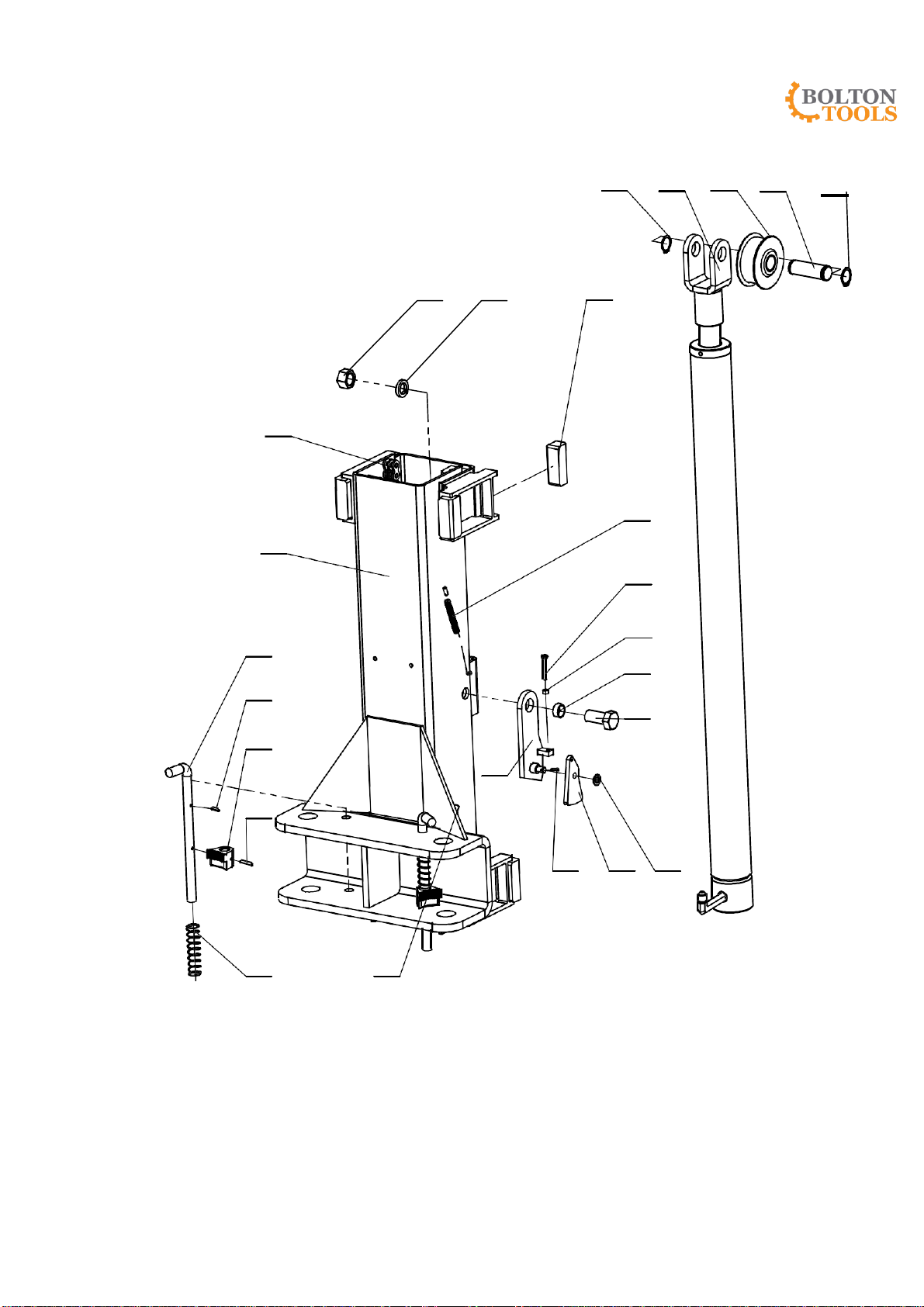
12
74
34
73
6
72
3
71
59
60
61
70
69
68
67
62
66
65
21
63
64
75 76 77 78 75
Fig 8

13

Table of contents
Popular Lifting System manuals by other brands


Floe
Floe VSD Assembly instructions

MARTINS Industries
MARTINS Industries MTWL user manual

Böcker
Böcker LMX 500 Operating and maintenance instructions

Genie
Genie S-105 Operator's manual

Pro-Lift
Pro-Lift T-5500 Operating instructions & parts manual

Tractel
Tractel Supertirfor TU16H Operation and maintenance manual

Terex
Terex Genie Z-34/22 IC Operator's manual

Rehasense
Rehasense Broadband Beam user manual

APlusLift
APlusLift HW-10KOH-A Installation & operation manual

Clarke
Clarke CBSS1 MOUNTING & USER INSTRUCTIONS

WOOD'S POWR-GRIP
WOOD'S POWR-GRIP MRTALPR4FS625DC instructions

Dhollandia
Dhollandia DH100 Series User's Manual Maintenance And Repair