Screen Technics INTERFIT Vertical Up Lift User manual

1
I
N
A
U
S
T
R
A
L
I
A
P
R
O
U
D
L
Y
B
U
I
L
T
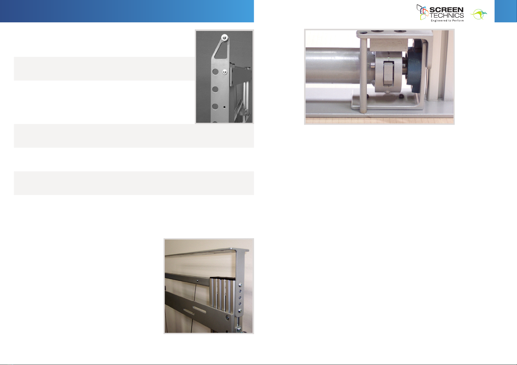
Front of unit - see horizontal mount plates - with overlapping slots for differing mount holes
STEP 4. To mount the panel unit utilise the long overlapping slots as the bolt positions, located
on the horizontal mounting plates (bolt heads cannot exceed l0mm).These plates are
also adjustable up and down in their slotted tracks. Always ensure that the bolts holding the
horizontal plates on are done up tight as they will be supporting the panel weight.
STEP 5. Install the power and data cables into the cable management system, this being a U
channel that moves up with the unit behind the lifting arms. use cable ties to keep cables in
position and allow enough slack so that no stretching or pinching of cables occurs during the
up/down travel.
Note: The cable management system can be reversed if required, you will need to readjust the back
attachment brackets in order to achieve this
STEP 6. Test that the unit will raises and lower safely and correctly.
Continued Over.../
INSTRUCTIONS - INTERFIT Vertical Up Lift
Thank you for purchasing a Screen Technics InterFit Vertical Up Lift and
please ensure to read the instruction fully before proceeding to install the
unit.
GENERAL ADVICE
• Beware of having your hands within the unit if operating up or down to avoid any ngers getting
caught or jammed.
• Please note operating the lift without a panel attached will need a weighted hand to ensure
smooth travel and to avoid fouling of the cables.
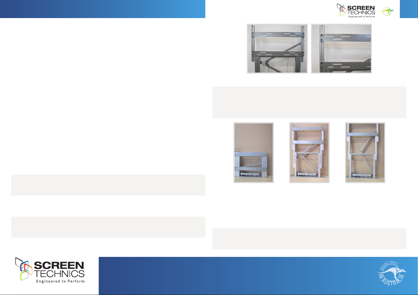
INSTALLATION ADVICE
• The unit is attached into / against a structure using the 4 off bottom base plate holes (10mm) and
the 2 off back support brackets. The back support brackets must be used in every installation to
stabilise the unit during operation.
• If attaching the lifting unit into an enclosed space the minimum internal dimensions are :
- Panel width plus 50mm
- Panel height Plus 50mm (can be reduced to 25mm if required).
- Panel thickness plus 115mm
• The lifter as a stand alone item is very quiet, but when placed in cabinetry will tend to
reverberate and make some noise, and as such you should ensure to increase the box (cabinet)
size if possible and to t sound deadening material inside the box, and this will greatly reduce the
environmental noise during operation.
STEP 1. Once the lifter is attached to the structure of the cabinet, provide power to the unit and
drive the lift upwards till it reaches it upper limit and stops.
STEP 2. Lower the lift using the motor while physically pushing down on the unit itself, as
normally it uses the weight of the panel to operate properly.
STEP 3. When you are satised the unit is operating properly raise it once again and install the
monitor screen.
•
•
•
Interfit Plasma Lift Vertical Up
•
•
•
Interfit Plasma Lift Vertical Up
•
•
•
•
•
•
•
•
•
•
•
•
•
•
•
info@screentechnics.com.au
screentechnics.com.au
AUSTRALIA
22-24 Suttor Road, Moss Vale NSW 2577
+61 2 4869 2100
NEW ZEALAND
44 Mahana Road, Te Rapa, Hamilton
0800 022 821
I
N
A
U
S
T
R
A
L
I
A
P
R
O
U
D
L
Y
B
U
I
L
T

2
I
N
A
U
S
T
R
A
L
I
A
P
R
O
U
D
L
Y
B
U
I
L
T
DOOR OPENING MECHANISM - STANDARD FITTING
The InterFit Vertical Up Lift comes with an integrated door opening
solution which works as follows:
STEP 1. Bolted to the LH side of the lifter up-right is a full height door guide
with a nylon runner wheel mounted at the top, which pushes open the
door on the upward travel.
STEP 2. You should mount the panel unit so that it is level with the top of
this nylon runner wheel - you may need to trim the door guide arm to
suit, making sure it still goes all the way to the bottom of the unit, so
the door does not get trapped under it when in the up position. You can
slide the door guide arm up or down by loosening the channel bolts
accordingly.
STEP 3. The unit is supplied with 2 off (White & Black) nylon wear pads that are designed to be tted
and to protect the underside of your opening door and glide along the edge of the door guide. Two
colours supplied for door colour matching purposes.
STEP 4. It is recommended that the hinge or pivot point for the door be 50mm back from the outer
edge of the door guide arm, as this will stop the door from over tilting and falling back away from
the mechanism.
STEP 5. If you don’t have enough room for the recommended 50mm pivot point then you will require
a spring tension system to pull the door against the lifting unit and stop the door overbalancing - a
solution is available from Screen Technics, please contact during oce hours to enquire.
Keep in mind the door weight / panel weight combination must be within published specications for
maximum unit capacity (marble or granite tops may be an issue). See design sheet for details.
Continued Over.../
INSTRUCTIONS - INTERFIT Vertical Up Lift
•
•
•
•
•
FIXED DOOR MOUNTING PLATE - OPTIONAL EXTRA FITTING
Enables a cut piece of cabinet or bench top (within
specied weight restrictions) to be ush mounted to the
top of the Lifting unit
• Enables a cut piece of cabinet or bench top (within
specied weight restrictions) to be ush mounted to
the top of the Lifting unit.
• T Section mounting plate is adjustable for height
utilising the side locking Allen Key bolts.
• Ensure that no obstructions exist with this style of
door tting as it will close ush with exiting cabinet
and possibly damage any items that get in the way.
• We recommend a non latching switch that
necessitates someone to keep pushing the control
switch until the unit is fully closed as a safety measure.
•
•
•
•
•
•
•
•
•
•
•
•
•
•
•
•
•
•
GENERAL ADVICE
• The up and down stop positions are set using the limit adjustment switches and are set at the
factory to allow maximum travel distance - due care must be taken if adjusting these limit
switches as any damage caused to the unit will void any warranty.
• The unit requires no maintenance throughout it’s life, although an inspection should be carried
out approximately every l8months.
• Please ensure any cables are safely away from any moving parts.
• When reversing direction of the travel in this unit a minimum delay of half a second is required
to be programmed in to prevent instant reversals.
Close up of mechanical fall arrester - safety rst!

3
I
N
A
U
S
T
R
A
L
I
A
P
R
O
U
D
L
Y
B
U
I
L
T
Continued Over.../
INSTRUCTIONS - INTERFIT Vertical Up Lift
240 VOLT MAINS CONNECTIONS
• The iConnect motor controller is supplied with a 240 V IEC power lead for connection to a
standard GPO.
• The 240 V output to the 4 core motor is via the supplied WAGO connector.
PIN WIRING CONFIGURATION
• Pin 1 Brown (Motor Down)
• Pin 2 Black (Motor Up)
• Pin 3 Green/Yellow (Earth)
• Pin 4 Blue (Neutral)
POWER ON INDICATOR (NEXT TO IR INPUT)
• When LED is Green, indicates mains 240V
present and iConnect module is on.
• When LED is Red, indicates that iConnect
module is in program mode.
FOR INFRA RED OPERATION YOU WILL REQUIRE
(SUPPLIED SEPARATELY)
• Screen Technics 2 Channel infra red
transmitter (Product Code 6500101)
• Screen Technics Connect infra red sensor
(Product Code 6500102 Length 300mm) or
(Product Code 6500103 Length 2000mm).
• Infra red receiver is connected to the IR
receiver input on iConnect module.
• Factory standard infra red operation is infra
red channel one (1).
• For individual infra red channel control (up to
9 Infra Red Channels can be programmed via
the 6 button infra red transmitter if required.
(Contact Screen Technics for details)
240 Volt Motor Controller for
4 Core Projection Screens, AV Lifters and Motorised Blinds
•
•
•
•
•
•
•
•
•
•
•
rcv
I
R
IR Receiver
Input
rcv
I
R
Infra Red
Receiver
rcv
I
R
IR Receiver
Input
•
•
•
•
•
•
•
•
•
•
•
rcv
I
R
IR Receiver
Input
rcv
I
R
Infra Red
Receiver
rcv
I
R
IR Receiver
Input
Mains
•
•
o
o
o
o
rcv
I
R
Connect Network
InOut
Contact Close
Input
IR Receiver
Input
Connect Network
In
Out
Next Connect Module
Maximum 9 Modules
rcv
I
R
M
Motor Output
240 V
Input
IEC
Socket
1 2 3 4
M
otor Wiring
P
in 1 - Brown Screen Down
P
in 2 - Black Screen Up
P
in 3 - Yellow/Green Earth
P
in 4 - Blue Neutral
Infra Red
Receiver
RJ12 Connector
6 Core wired
straight through
In
Out

4
I
N
A
U
S
T
R
A
L
I
A
P
R
O
U
D
L
Y
B
U
I
L
T
INSTRUCTIONS - INTERFIT Vertical Up Lift
CONNECT NETWORK CONNECTION
• The connect network allows for the connection of up to nine (9) iConnect 240V or 24V
modules.
• Connection between modules is via a RJ12 6 Core cable wired straight through.
• Connection is made by connecting from the RJ12 connect network out to the RJ12 connect
network in.
• A 10 metre RJ12 Connect daisy chain cable is available (Product Code 6500104).
CONTACT CLOSE INPUT
• Requires two (2) contacts - one for up command and one for down command.
• Contact operation is momentary dry contact, command is sent when contact is reopened
(Lagging Contact)
• Contact close input is local only, can be parallel wired to other modules for multiple
control.
• Contact close can be reprogrammed to single latched mode by using the 6 button infra red
transmitter if required. (Contact Screen Technics for details)
• Two button impulse switches are available (Product Code 3500998)
INTERFACING WITH THIRD PARTY CONTROL SYSTEMS
The iConnect module can be connected to the iReply (Product Code 6500300) interface via the
connect network to provide
• RS232 control
• RS485 Control
• TCP/IP Control
• USB Control
(Contact Screen Technics for details.)
FACTORY RESET PROCEDURE
Should you experience problems with the operation of the iConnect module at the time of
installation, a factory reset can be initiated to conrm operational integrity of the iConnect
module.
• Infra Red receiver must be connected to the iConnect module
• Disconnect module from mains power for 20 seconds
• Reconnect module to mains power.
• LED on iConnect module will change from green to red (module is now in program mode).
• Using the 6 button infra red remote push buttons in the sequence of:
-Stop 1 - Stop 1 - Stop 2 - Stop 2 - Stop 1 - Stop 1
- To conrm that the reset was performed the projection screen, AV lifter or roller blind will
jiggle up and down. The module is now reset to factory standard (Infra red operation is
group one (1) and contact close is momentary operation.
•
•
•
•
•
•
•
•
•
•
•
•
•
•
o
o
Contact Close
Input
•
•
•
•
•
•
•
•
•
•
•
rcv
I
R
IR Receiver
Input
rcv
I
R
Infra Red
Receiver
rcv
I
R
IR Receiver
Input
MAINTENANCE AND SERVICING
Although this unit does not require any regular servicing, it is recommended that a visual
inspection of the device take place on a scheduled yearly basis inspecting for the following:
Please note that no persons should be beneath the device during this testing proceedure, or in
day to day operation.
1. Inspect wire cabling for any fraying, and that the cable is winding neat on the cable winding
drum.
2. Inspect the power and AV source cable that travels up and down with the unit to ensure no
damage or tangling has occurred.
3. Operate the unit fully down and up to ensure smooth operation and inspect the fall arrester
mechanism attached to the winding tube for free travel every rotation (it will fall into place
and make a clicking sound).
4. A full visual inspection looking for any part of the device that appears to be faulty or failing.
Should any concerns arise from these inspections please immediately seek advice from Screen
Technics, and secure the device so that it is not operational until all matters are resolved.
Should you have any questions regarding the installation of our products please call our sales
desk on +61 2 4869 2100 for assistance
This manual suits for next models
4
Other Screen Technics Lifting System manuals