7
The instructions will enable you to assemble and
maintain your lawn mower properly. Always observe the
“SAFETY REGULATIONS”. We recommend that you
write down the serial number and purchase date in your
user manual, so that you will always have it at hand.
CUSTOMER RESPONSIBILITIES
• Read and observe the safety regulations contained
in this manual.
• Follow a regular schedule for maintaining, caring for
and using your lawnmower.
• Follow the instructions in the “Customer
responsibilities” and “Storage” sections of this
owner’s manual.
• Remember that the operator is responsible for
accidents with other persons or their property.
ASSEMBLY
Read these instructions and this manual in its entirety
before you attempt to assemble or operate your new lawn
mower.
IMPORTANT: THIS LAWN MOWER IS SHIPPED
WITHOUT OIL OR FUEL IN THE ENGINE.
Your new lawn mower has been assembled at the
factory with the exception of those parts left unassembled
for shipping purposes. All parts such as nuts, washers,
bolts, etc., necessary to complete the assembly have
been placed in the parts bag. To ensure safe and proper
operation of your lawn mower. All parts and hardware you
assemble must be tightened securely. Use the correct tools
as necessary to ensure proper tightness.
1. TO REMOVE LAWN MOWER FROM CARTON
• Remove loose parts included with mower.
• Cut down two end corners of carton and lay end panel
down at.
• Remove all packing materials except padding
between upper and lower handle.
• Roll lawn mower out of carton and check carton
thoroughly for additional loose parts.
2. HOW TO SET UP YOUR LAWN MOWER
IMPORTANT: UNFOLD HANDLE CAREFULLY
SO AS NOT TO PINCH OR DAMAGE CONTROL
CABLES.
• Lift and unfold upper handle to desired height and pull
two levers on both sides to lock upper handle. Refer to
Service and Adjustments section.
• CAUTION: Unfold the handle carefully to avoid pinching
and damaging the control cables.
• Your handles may be adjusted for your mowing
comfort. Refer to Service and Adjustments section
of this manual.
3. TO ASSEMBLE GRASS CATCHER
• Put grass catcher frame into grass bag with rigid
part of bag on the bottom. Make sure the frame
handle is outside of the bag top.
• Slip vinyl bindings over frame.
NOTE: If vinyl bindings are too stiff, hold them in warm
water for a few minutes. If bag gets wet, let it dry
before using.
SERIAL NUMBER ______________________
DATE OF PURCHASE __________________
THE MODEL AND SERIAL NUMBERS WILL
BE FOUND ON A DECAL ATTACHED TO THE
REAR OF THE LAWNMOWER HOUSING.
YOU SHOULD RECORD BOTH SERIAL
NUMBERS AND DATE OF PURCHASE AND
KEEP IN A SAFE PLACE FOR FUTURE
REFERENCE.
LIFT & TURN TO
DESIRED POSITION
LOCKING
LEVER
FIG. 1
LOCKING
LEVER
FIG. 2
PUSH
TO
LOCK
GRASS BAG
FRAME
8
CAUTION: Unfold the handle carefully to avoid
pinching and damaging the control cables.
• Remove any packaging material from around the
control bar.
• Your handles may be adjusted for your mowing
comfort. Refer to Service and Adjustments section
of this manual (except 2in1 mower).
3. TO ASSEMBLE GRASS CATCHER
• Put grass catcher frame into grass bag with rigid
part of bag on the bottom. Make sure the frame
handle is outside of the bag top.
• Slip vinyl bindings over frame.
NOTE: If vinyl bindings are too stiff, hold them in warm
water for a few minutes. If bags get wet, let it dry before
using.
4. ASSEMBLE ENGINE STARTER KNOB
• Pull the knob of starter rope back to the hook ring
on upper handle. Assemble the rope into the zone
starter ring through the opening of hook ring.
• Always keep starter rope in hook ring during all
mowing work.
OPERATION
OPERATION
DRIVE CONTROL BAR-used to engage power-pro-
pelled forward motion lawn mower.
THROTTLE CONTROL-used for starting the engine
and allows you to select either fast or slow engine
speed.
STARTER HANDLE-used for starting the engine.
MULCHER PLUG-located at the discharge opening,
must be removed when converting to bagging operation.
(For 3in1 mower)
MULCHER DOOR-allows conversion to discharge
or bagging operation.(for 3in1/2in1 mower)
PRIMER-pumps additional fuel from the carburetor
to the cylinder for use when starting a cold B&S engine.
OPERATOR PRESENCE CONTROL BAR-must be
held down to the handle to start the engine. Release
to stop the engine.
GB
WARNING: The operation of any lawn
mower can result in foreign objects thrown
into the eyes, which can result in severe
eye damage. Always wear safety glasses or eye
Shields while operating your lawn mower or per-
forming any adjustments or repairs. We recom-
mend wide vision safety mask over spectacles or
standard safety glasses.
HOW TO USE YOUR LAWN MOWER
ENGINE SPEED
A throttle located on the side of the upper handle
controls the engine speed. Fast position is for
normal cutting, trimming and better grass bagging.
Slow position is for light cutting, trimming and fuel
economy.
ENGINE CONTROL ZONE
Your lawn mower is equipped with an operator
presence control bar which requires the operator to
be positioned behind the lawn mower handle to start
and operate the lawn mower.
06
TO OPERATE DRIVE SYSTEM(See Fig.6)
To start forward motion, lift drive control bar up to
handle.
Fig.6
Engine throttle
control lever Start
Slow
Fast
Engine brake handle/Blade brake handle(Model with BBC)
Drive speed control lever
Engine
Wheel
Bumper
Chassis
Upper handle
Rear cover
Grass catcher
Starter knob
Throttle and drive controler
Height adjustment lever
Locking lever
Adjuster
Height adjustment lever
Height adjustment lever
Locking lever
Air filter
Fig.8
To stop forward motion, release drive control bar.
IMPORTANT: ALWAYS KEEP DRIVE CONTROL
FULLY ENGAGEDAGAINST HANDLE WHEN IN USE.
TO ATTACH GRASS CATCHER
1.Lift the rear door of the lawn mower and place the
grass catcher frame side hooks into the slots of the
rear door.
2.The grass catcher is secured to the lawn mower
housing when the rear door is lowered onto the grass
catcher frame.
stop start forward
-First press the lever slightly downwards and adjust
to the desired speed. The lever automatically clicks
back into the nearest new position.
-Position rabbit =fast(max.speed)
-Position tortoise =slow (min.speed)
All four wheels are adjusted by a single lever except
the model 2in1. The 2in1 mower has two levers to
adjust the front wheel and rear wheel individually.
You can set the cutting height to the desired height
to fit different terrain. Pull the lever out from the catch,
move to the desired position and let it fall back into
the catch.
WARNING: The lawnmower can only be used on
level lawns if the lowest cutting height is being
used.
NOTE: The speed may only be adjusted
ADJUSTING THE DRIVE SPEED (See Fig.8)
for speed adjustable model
when the engine is running in order to
avoid damage!
-The driving speed can be continuously adjusted by us-
ing the adjustment lever mounted on the upper hand.
WHEEL ADJUSTER
LEVER
Fig.9
Fig.10
ENGAGE THE BLADE-CLUTCH (See Fig.7)
only for machines with BBC
Fig.7
Blade clutch lever
running.
The mower is adjusted to one cutting height upon
delivery.
Never adjust the cutting height with the motor still
ADJUSTING THE CUTTING HEIGHT (See Fig. 9)
Fig.6
Upper handle
Step 1
Step 2
Slow
(tortoise)
Fast
(rabbit)
Drivespeed
controllever
for low cut
Raise wheels
for high cut
Lower wheels
for high cut
Lower wheels
for low cut
Raise wheels
WHEEL ADJUSTER
LEVER
CENTRAL ADJUSTER ON RIGHT SIDE
ADJUSTER ON EACH WHEEL
2.Press the blade-clutch-lever close to the handle-
bar completely to engage blade.
3.Release the lever about 2'' away from the hand-
lebar, until the lever make a 'click' sound. And
then re-press the lever and hold it togather with
the handlebar.
4.Release the blade-clutch-lever completely to
dis-engage and stop the blade.
1. For safety, the blade-clutch-lever can not be en-
gaged directly after releasing. Push the lever
forward until it make a 'click' sound, and then
you can engaged the clutch again.
05
GB
Fig.5
OPERATION
DRIVE CONTROL BAR-used to engage power-pro-
pelled forward motion lawn mower.
THROTTLE CONTROL-used for starting the engine
and allows you to select either fast or slow engine
speed.
STARTER HANDLE-used for starting the engine.
MULCHER PLUG-located at the discharge opening,
must be removed when converting to bagging operation.
(For 3in1 mower)
MULCHER DOOR-allows conversion to discharge
or bagging operation.(for 3in1/2in1 mower)
PRIMER-pumps additional fuel from the carburetor
to the cylinder for use when starting a cold B&S engine.
OPERATOR PRESENCE CONTROL BAR-must be
held down to the handle to start the engine. Release
to stop the engine.
GB
WARNING: The operation of any lawn
mower can result in foreign objects thrown
into the eyes, which can result in severe
eye damage. Always wear safety glasses or eye
Shields while operating your lawn mower or per-
forming any adjustments or repairs. We recom-
mend wide vision safety mask over spectacles or
standard safety glasses.
HOW TO USE YOUR LAWN MOWER
ENGINE SPEED
A throttle located on the side of the upper handle
controls the engine speed. Fast position is for
normal cutting, trimming and better grass bagging.
Slow position is for light cutting, trimming and fuel
economy.
ENGINE CONTROL ZONE
Your lawn mower is equipped with an operator
presence control bar which requires the operator to
be positioned behind the lawn mower handle to start
and operate the lawn mower.
06
TO OPERATE DRIVE SYSTEM(See Fig.6)
To start forward motion, lift drive control bar up to
handle.
Fig.6
Engine throttle
control lever Start
Slow
Fast
Engine brake handle/Blade brake handle(Model with BBC)
Drive speed control lever
Engine
Wheel
Bumper
Chassis
Upper handle
Rear cover
Grass catcher
Starter knob
Throttle and drive controler
Height adjustment lever
Locking lever
Adjuster
Height adjustment lever
Height adjustment lever
Locking lever
Air filter
Fig.8
To stop forward motion, release drive control bar.
IMPORTANT: ALWAYS KEEP DRIVE CONTROL
FULLY ENGAGEDAGAINST HANDLE WHEN IN USE.
TO ATTACH GRASS CATCHER
1.Lift the rear door of the lawn mower and place the
grass catcher frame side hooks into the slots of the
rear door.
2.The grass catcher is secured to the lawn mower
housing when the rear door is lowered onto the grass
catcher frame.
stop start forward
-First press the lever slightly downwards and adjust
to the desired speed. The lever automatically clicks
back into the nearest new position.
-Position rabbit =fast(max.speed)
-Position tortoise =slow (min.speed)
All four wheels are adjusted by a single lever except
the model 2in1. The 2in1 mower has two levers to
adjust the front wheel and rear wheel individually.
You can set the cutting height to the desired height
to fit different terrain. Pull the lever out from the catch,
move to the desired position and let it fall back into
the catch.
WARNING: The lawnmower can only be used on
level lawns if the lowest cutting height is being
used.
NOTE: The speed may only be adjusted
ADJUSTING THE DRIVE SPEED (See Fig.8)
for speed adjustable model
when the engine is running in order to
avoid damage!
-The driving speed can be continuously adjusted by us-
ing the adjustment lever mounted on the upper hand.
WHEEL ADJUSTER
LEVER
Fig.9
Fig.10
ENGAGE THE BLADE-CLUTCH (See Fig.7)
only for machines with BBC
Fig.7
Blade clutch lever
running.
The mower is adjusted to one cutting height upon
delivery.
Never adjust the cutting height with the motor still
ADJUSTING THE CUTTING HEIGHT (See Fig. 9)
Fig.6
Upper handle
Step 1
Step 2
Slow
(tortoise)
Fast
(rabbit)
Drivespeed
controllever
for low cut
Raise wheels
for high cut
Lower wheels
for high cut
Lower wheels
for low cut
Raise wheels
WHEEL ADJUSTER
LEVER
CENTRAL ADJUSTER ON RIGHT SIDE
ADJUSTER ON EACH WHEEL
2.Press the blade-clutch-lever close to the handle-
bar completely to engage blade.
3.Release the lever about 2'' away from the hand-
lebar, until the lever make a 'click' sound. And
then re-press the lever and hold it togather with
the handlebar.
4.Release the blade-clutch-lever completely to
dis-engage and stop the blade.
1. For safety, the blade-clutch-lever can not be en-
gaged directly after releasing. Push the lever
forward until it make a 'click' sound, and then
you can engaged the clutch again.
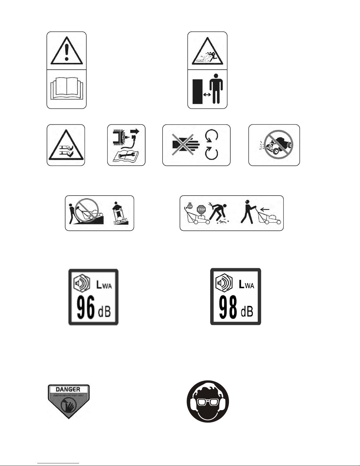
These symbols may appear on your lawnmower or in literature supplied with the product. Learn and understand their meaning.
CAUTION: Wear protective gloves during
operation of setting up your mower.
WARNING: The safety position for starting the
engine is at the back of upper handle. Users
must keep the rope always in the middle of the hook
ring during starting the engine and mowing work. It
is dangerous to start an engine away from the safety
position, which could lead to serious injury to feet or
bodily parts.
GBGB
OPERATION
Fig.4
05 06
WB436SB AL V
WB536SB ALV
Drive control handle
Height adjustment
meanwhile pull the knob of starter rope back to the
hook ring on upper handle, assemble. The rope into
the hook ring through the opening of hook ring .
Always keep starter rope in hook ring during all
mowing work.
IV. ASSEMBLE ENGINE STARTER KNOB
Press down engine brake handle by left hand, and
WARNING:The safety positionof start-
ing engineis at theback of upperhandle.
Users must keep the rope always in the
middle of thehook ringduringstarting engine
andmowingwork. It is dangerto starting engine
away from thesafetyposition,which will lead to
theriskoffeethurting.
CAUTION: Wear protective gloves
during operation of setting up your
mower.
WARNING: The operation of any lawn
mower can result in foreign objects thrown
into the eyes, which can result in severe
eye damage. Always wear safety glasses
or eye shields while operating your lawn
mower or performing any adjustments or
repairs. We recommend wide vision safety
mask over spectacles or standard safety
glasses.
HOW TO USE YOUR LAWN MOWER
ENGINE SPEED
Athrottle located on the side of the upper handle
controls the engine speed. Fast position is for
DRIVE CONTROL BAR-used to engage power-pro-
pelled forward motion lawn mower.
THROTTLE CONTROL-used for starting the engine
and allows you to select either fast or slow engine
speed.
STARTER HANDLE-used for starting the engine.
PRIMER-pumps additional fuel from the carburetor
to the cylinder for use when starting a cold engine.
OPERATOR PRESENCE CONTROL BAR-engine
brake,it must be held down to the handle to start the
engine. Release it to stop the engine.
and allows you to select either fast of slow speed.
DRIVE SPEED LEVER -used for adjusting the drive speed
normal cutting, trimming and better grass bagging.
Slow position is for light cutting, trimming and fuel
economy.
Your lawn mower is equipped with an operator
presence control bar which requires the operator to
be positioned behind the lawn mower handle to start
and operate the lawn mower.
ENGINE CONTROL ZONE
TO OPERATE DRIVE SYSTEM
To start forward motion, lift drive control bar up to
handle.
To stop forward motion, release drive control bar.
IMPORTANT: ALWAYS KEEP DRIVE CONTROL
FULLY ENGAGED AGAINST HANDLE WHEN IN USE.
Fig.5
Fig.3
Hook ring
Starter rope