C.R. Laurence INTELLI-TRACK User manual

C.R. Laurence Co., Inc. • 2503 E. Vernon Ave., Los Angeles, CA 90058 •1.800.421.6144 •crlaurence.com
INTELLITRACK™
STACKING PARTITION SYSTEM
11M0272
GLASS DRILL INSTRUCTION MANUAL
INSTALLATION INSTRUCTIONS
crlaurence.com

INTELLI-TRACK™ SPS SYSTEM
P. 2
C.R. Laurence Co., Inc. • 2503 E. Vernon Ave., Los Angeles, CA 90058 •1.800.421.6144 •crlaurence.com
INTRODUCTION
INTELLI-TRACK™SPS
Tools Required
• 7/8" Open-End Wrench (Two)
• 9/16" Socket Hex
• Ratchet Wrench with 4" Extension
• 3/16" Hex Bit Socket or T-Handle Hex Tool
• 7/32" Hex Bit Socket or T-Handle Hex Tool
• 2 mm Hex Bit Socket or T-Handle Hex Tool
• Hammer with Smooth Face
• Saw Horses (Two)
• CRL PLS2 Palm Laser Level or
Optional Conventional Level
• CRL Glass Cleaner
• Cordless Drill
• #1 Phillips Screwdriver
• Circular Table/Bench Saw with Aluminum
Cutting Blade
The rapidly changing technology within the architectural aluminum products industry demands that C.R. Laurence/U.S. Aluminum reserve the right to
revise, discontinue, or change any product line, specification, or electronic media without prior written notice.
NOTE: Dimensions in parentheses ( ) are millimeters unless otherwise noted.
IMPORTANT NOTES:
1) The CRL Intelli-Track™ Stacking Partition System has unique structural support requirements. Please request or
download, free of charge, our "SPS Structural Engineering Design Guide" for use by the architectural/engineering
design group on this project.
2) Fasten Track to the overhead support structure with 3/8" (9.5) Hex Head type fasteners made from one of the
following materials: A307 galvanized or A316 stainless steel. Always use Lock Washers.
3) All glass should be fully tempered with polished edges. Laminated glass should not be used with CRL Wedge-Lock
Rails. However, laminated glass can be used for fully framed wall Panel installations.
4) Track is pre-drilled to allow for mounting to optional suspension brackets or directly to concrete, metal or wood.
Please consult with CRL Technical Sales. Fasteners to attach Track or brackets to structure are not provided by CRL.
5) The circular table/bench saw must be capable of cutting 3/8" (9.5) thick aluminum sections. The diameter of the
aluminum cutting blade must accommodate an extrusion profile with the following dimensions: 4-7/8" (123.8)
wide x 3-9/16" (90.5) tall. Miter cutting capability will not be required in most cases, as CRL provides prefabricated
corners and intersections.

INTELLI-TRACK™ SPS SYSTEM
P. 3
C.R. Laurence Co., Inc. • 2503 E. Vernon Ave., Los Angeles, CA 90058 •1.800.421.6144 •crlaurence.com
COMPONENT PLACEMENT PLAN
PLAN VIEW - TOP RAILS
ELEVATION OF TOP RAILS - FROM OUTSIDE
ELEVATION OF BOTTOM RAILS - FROM OUTSIDE
BTM RAIL #1
BTM RAIL #2BTM RAIL #3
TOP RAIL #1
TOP RAIL #2TOP RAIL #3
P.O.951027
SVE910 CUT THE FOLLOWING
1 @ 113.908
1 @ 11.655
1 @ 26.077
1 @ 11.487
CYLINDER OUT
THUMBTURN IN
FLOOR CLOSER
RECEIVER
143.563
2.625
47.688
2.625
3.375
RECEIVER SLIDE BOLT
CYLINDER OUT
THUMBTURN IN
THUMBTURN IN
11.655 12.000 6.000 113.908
26.077
11.487
143.563
END STOP
END STOP
1 @ 6.00
DOOR PIVOT
1
1
2
2
3
3
4
4
A A
B B
PRODUCT:
DWG NO
DESCRIPTION
SCALE
DRAWN DATE
PA RT:
UNLESS OTHERWISE SPECIFIED
DIMENSIONS ARE IN INCHES
TOLERANCE IS:
Frac.
.XX
.XXX
Angles
Radial
REV DATE BY
C.R.Laurence Co., Inc.
2100 W. 38th.Street
Vernon, Ca, 90058
PART NUMBER
PHONE: (323) 588-1281
FAX: (323) 232-2523
NOTE
THIS DRAWING AND THE DESIGN SHOWN THEREIN IS THE PROPERTY OF
C.R.LAURENCE CO., INC
AND USE OR COPIES THEREOF CANNOT BE MADE
WITHOUT WRITTEN CONSENT.
nts
Componet Placement Plan
SPS Installation Instructions
Sample Shop Drawing
Provided by C.R. Laurence
Figure 1
Read these instructions completely before beginning the installation.
Component Placement Plan (CPP)
Review the Component Placement Plan provided by CRL to determine placement of the Track components.
Each component is labeled to match its designated location on the plan.
PHASE ONE
SPS Track Installation
Before Track Installation, Consider the Following:
1. CRL provides mounting systems for attaching Track directly to concrete, metal, and wood, as well as mounting
systems for suspending Track beneath concrete and steel structures. When mounting Track directly to building
structure, it is important that the mounting surface be level and parallel to the floor. The use of CRL shims to
correct minor variations is acceptable.
2. Measure from the Track-mounting surface to the floor at multiple locations. The floor should be flat in all areas
of Panel movement. Abrupt changes in elevation can force all Panels to be elevated above the nominal 1/4" (6.4)
floor clearance, as they must all clear the highest elevation when moving toward the parking area.
3. 1/4" (6.4) is the nominal clearance between the floor and bottom Wall Panel Rails; 5/16" (7.9) is the maximum
recommended clearance.

INTELLI-TRACK™ SPS SYSTEM
P. 4
C.R. Laurence Co., Inc. • 2503 E. Vernon Ave., Los Angeles, CA 90058 •1.800.421.6144 •crlaurence.com
Figure 3
2. Position all Stops and Door Top Pivots in their approximate locations in the Track as detailed by the CPP
(Fig 3). SPS Door Top Pivot and Adjustable Roller Stop final adjustments will be done in Phase 2 after
Track has been completely installed.
Figure 2
Track Layout Procedure
1. Lay out the Track on the floor as detailed by the Component Placement Plan (CPP) . This will verify that all
component pieces are present and correct (Fig 2).

INTELLI-TRACK™ SPS SYSTEM
P. 5
C.R. Laurence Co., Inc. • 2503 E. Vernon Ave., Los Angeles, CA 90058 •1.800.421.6144 •crlaurence.com
Install the Parking Area Assembly
Install the Parking Area Assembly(ies), align and fasten to the overhead support structure. Use 3/8"
Hex Head fasteners made from one of the following materials: A307 Galvanized or A316 Stainless Steel.
NOTE: ALWAYS USE LOCK WASHERS.
Figure 4
Install the Parking Area First
Figure 5
Install the Remaining Track
Components
Install the Remaining Track Sections
NOTE: If your SPS System was ordered prefabricated, proceed to Step 3 on Page 6.

INTELLI-TRACK™ SPS SYSTEM
P. 6
C.R. Laurence Co., Inc. • 2503 E. Vernon Ave., Los Angeles, CA 90058 •1.800.421.6144 •crlaurence.com
2. Measure back to the Roller Access Splice to determine your cut lengths of the remaining Track,
allowing for slight clearance for later removal of the Roller Access Splice.
Roller Access Splice
Figure 6
Measure from the
Roller Access Splice
when using stock lengths.
3. Install four Drive-In Alignment Strips at all Track joints, except at the Roller Access Splice. Each Drive-In Alignment
Strip installs barbed-end first, align with the receiving socket in the Track extrusion, and then drive-in with a smooth
faced hammer. One half of each Alignment Strip’s length should remain exposed, ready to engage the next Track
section (Fig. 7).
4. Install the remaining Track section(s) working toward the Roller Access Splice and carefully following the CPP.
Use 3.8" Hex Head type fasteners made from one of the following materials: A307 Galvanized or A316 Stainless Steel.
NOTE: ALWAYS USE LOCK WASHERS.
Figure 7
Secure Track Sections with
Drive-In Alignment Strips.
Do not use on either end of
the Roller Access Splice.
Drive-In Alignment Strips
1. Locate and install the Roller Access Splice as shown on the CPP. If your SPS System was ordered with stock length
Track(s), The Roller Access Splice is pre-drilled and ready to receive two fasteners. Align the Roller Access Splice
with the end of the Parking Area Assembly and fasten into place (Fig 5). Use 3/8" Hex Head type fasteners made from
one of the following materials: A307 Galvanized or A316 Stainless Steel.
NOTE: ALWAYS USE LOCK WASHERS.

INTELLI-TRACK™ SPS SYSTEM
P. 7
C.R. Laurence Co., Inc. • 2503 E. Vernon Ave., Los Angeles, CA 90058 •1.800.421.6144 •crlaurence.com
NOTE: Before installing the Track section(s) immediately before and after the Roller Access Splice you will need to
remove the Roller Access Splice, if previously installed, to allow room to engage the Drive-In Alignment Strips.
1. Align the Roller Access Splice with the end of the Parking Area Assembly and/or Track section(s). Fasten into place.
Use 3/8" Hex Head type fasteners made from one of the following materials: A307 Galvanized or A316 Stainless Steel.
NOTE: ALWAYS USE LOCK WASHERS.
2. Ensure a slight clearance for later removal of the Roller Access Splice.
Install Roller Access Splice
THIS FIRST PHASE OF THE INSTALLATION IS COMPLETE
NOTE: If you have not previously installed the Roller Access Splice, do so now. The Roller Access Splice is pre-drilled
and ready to receive two fasteners.

INTELLI-TRACK™ SPS SYSTEM
P. 8
C.R. Laurence Co., Inc. • 2503 E. Vernon Ave., Los Angeles, CA 90058 •1.800.421.6144 •crlaurence.com
NOTE: Sliding Wall Panels must not be allowed to hit the end of Pivoting Doors. To prevent this from happening a
Stop must be installed between the free-swinging end of Pivoting Doors and adjacent Sliding Wall Panels
(Fig. 4).
Look at the CPP to determine the order for inserting Pivots and Stops into the Track via the opening for the Roller
Access Splice. Using 7/32" Hex Bit Socket or T-Handle Hex Tool, remove the clamping plate that is exposed on the
bottom of Pivots and Stops. Make certain that the set screws and sliding Pivot Pin do not extend above the top surface,
as this will prevent collision with Track Mounting Bolts while sliding them along the Track to the installation location.
NOTE: Pivots do not have a special orientation during insertion into the Track, but Stops must be rotated such that
their rubber bumpers face toward the adjacent Sliding Wall Panel.
Insert Pivots and Stops
Figure 4
Rubber Bumper Stops
Facing Sliding Wall Panel
Door Stop
Fixed Pivot

INTELLI-TRACK™ SPS SYSTEM
P. 9
C.R. Laurence Co., Inc. • 2503 E. Vernon Ave., Los Angeles, CA 90058 •1.800.421.6144 •crlaurence.com
1. Install a Stop at all locations where a Sliding Wall Panel can collide with building structure and Pivoting Doors.
Make certain that the Stop's rubber bumpers face toward the Sliding Wall Panels (Fig 5).
2. Using a 3/16" Hex Drive Socket or T-Handle Hex Tool, turn the set screw clockwise until it sits tight against
the top of the Track (Fig 6).
3. Using a 7/32" Hex Drive Socket or T-Handle Hex Tool, re-attach the Clamping Plate. The supplied Loctite®
Threadlocker must be applied to the threads, preventing loosening. Tighten this screw firmly as its clamping
action prevents the Stop from moving (Fig 7).
Figure 6 Figure 7
Rubber Stops
Sliding
Panel
Figure 5
Insert Pivots and Stops (Continued)
Position and Secure the Stop

INTELLI-TRACK™ SPS SYSTEM
P. 10
C.R. Laurence Co., Inc. • 2503 E. Vernon Ave., Los Angeles, CA 90058 •1.800.421.6144 •crlaurence.com
1. The centerline of the pivot pin should be positioned
at 2-3/4" (69.8) from the finished wall.
2. Using a 3/16" Hex Drive Socket or T-Handle Hex Tool
turn the two set screws clockwise until they sit tight
against the top of the Track.
Position and Secure the Top Door Pivot
3. Using a 7/32" Hex Socket or T-Handle Hex Tool,
re-attach the clamping plate. Apply the supplied
Loctite®Threadlocker to the threads. Tighten the
screw firmly.
2-3/4"
(69.8)
Insert Pivots and Stops (Continued)

INTELLI-TRACK™ SPS SYSTEM
P. 11
C.R. Laurence Co., Inc. • 2503 E. Vernon Ave., Los Angeles, CA 90058 •1.800.421.6144 •crlaurence.com
COMPONENT PLACEMENT PLAN
PLAN VIEW - TOP RAILS
ELEVATION OF TOP RAILS - FROM OUTSIDE
ELEVATION OF BOTTOM RAILS - FROM OUTSIDE
BTM RAIL #1
BTM RAIL #2BTM RAIL #3
TOP RAIL #1
TOP RAIL #2TOP RAIL #3
P.O.951027
SVE910 CUT THE FOLLOWING
1 @ 113.908
1 @ 11.655
1 @ 26.077
1 @ 11.487
CYLINDER OUT
THUMBTURN IN
FLOOR CLOSER
RECEIVER
143.563
2.625
47.688
2.625
3.375
RECEIVER SLIDE BOLT
CYLINDER OUT
THUMBTURN IN
THUMBTURN IN
11.655 12.000 6.000 113.908
26.077
11.487
143.563
END STOP
END STOP
1 @ 6.00
DOOR PIVOT
1
1
2
2
3
3
4
4
A A
B B
PRODUCT:
DWG NO
DESCRIPTION
SCALE
DRAWN DATE
PA RT:
UNLESS OTHERWISE SPECIFIED
DIMENSIONS ARE IN INCHES
TOLERANCE IS:
Frac.
.XX
.XXX
Angles
Radial
REV DATE BY
C.R.Laurence Co., Inc.
2100 W. 38th.Street
Vernon, Ca, 90058
PART NUMBER
PHONE: (323) 588-1281
FAX: (323) 232-2523
NOTE
THIS DRAWING AND THE DESIGN SHOWN THEREIN IS THE PROPERTY OF
C.R.LAURENCE CO., INC
AND USE OR COPIES THEREOF CANNOT BE MADE
WITHOUT WRITTEN CONSENT.
nts
Componet Placement Plan
SPS Installation Instructions
PHASE TWO
Review the Component Placement Plan provided by CRL to determine Wall Panel Bottom Rail
configuration, size, and sequence number. NOTE: The #1 Wall Panel is the Panel farthest from the parking
area. Each component is labeled to match its designated location on the plan.
Component Placement Plan (CPP)
SPS Glass Wall Panel Assembly, Installation

INTELLI-TRACK™ SPS SYSTEM
P. 12
C.R. Laurence Co., Inc. • 2503 E. Vernon Ave., Los Angeles, CA 90058 •1.800.421.6144 •crlaurence.com
NOTE: If field conditions have been carefully inspected, glass can be fabricated before Track installation,
but the safest route is to measure for glass after the Track is installed.
CRL Technical Sales can provide glass deduction dimensions for the various combinations of Glass Wall
Panel Rail profile heights, in combination with the Supporting Track (at the nominal roller height adjustment).
The CRL SPS allows for plus and minus 3/16" (4.8) height adjustment from nominal, for a total of 3/8" (9.5)
height adjustment.
Determine Glass Sizes

INTELLI-TRACK™ SPS SYSTEM
P. 13
C.R. Laurence Co., Inc. • 2503 E. Vernon Ave., Los Angeles, CA 90058 •1.800.421.6144 •crlaurence.com
1. Lay your glass panel flat on two sawhorses or other appropriate support structure. At each end of the Wall Panel
Rails are Spacer Blocks (used to keep the Wedge-Lock™ Clamps separated). Slip the Wall Panel Rail onto the
glass and align the vertical edge of the glass even with the End Cap. Two Wall Panel Rails do not yet have End Caps,
so align the edge of the glass to protrude from both ends of the Wall Panel Rail evenly.
Assemble Wall Panels
Measure from the bottom of the Track to the floor, deduct for the top and bottom rails, as well as the nominal 1/4" (6.4)
clearance above the floor. The determination of Panel width requires many considerations, but in normal conditions the glass
widths match the Wall Panel Rails and Door Rails. All vertical gaps between walls, wall Panel rails, and door rails
are calculated at 1/8” unless specific instructions were given at time of ordering. Refer to CPP to verify.
NOTE: All glass should be fully tempered. Laminated glass should not be used with CRL Wedge-Lock Rails when fabricating
Moving Wall Panels. However, laminated glass can be used for fully framed wall Panels (supplied by others).
Wall Panel Rail
Wall Panel Rail
Glass
INTELLI-TRACK™ SPS SYSTEM
P. 14
C.R. Laurence Co., Inc. • 2503 E. Vernon Ave., Los Angeles, CA 90058 •1.800.421.6144 •crlaurence.com
2. After this alignment is achieved, pull the Spacer Blocks from each end of the Wall Panel Rail, then push the Wall
Panel Rail toward the glass until the glass bottoms out in the Wedge-Lock™ Channels. Check again for alignment.
3. Tighten a Socket Head Cap Screw in the middle of the channel with the 3/16" T-Handle Hex Tool, supplied.
Top Wall Panel Rail Socket Head Cap Screws are accessed through holes in a cover plate. Tighten all of the
Socket Head Cap Screws working left to right using the 3/16" T-Handle Hex Tool.
Assemble Wall Panels (Continued)

INTELLI-TRACK™ SPS SYSTEM
P. 15
C.R. Laurence Co., Inc. • 2503 E. Vernon Ave., Los Angeles, CA 90058 •1.800.421.6144 •crlaurence.com
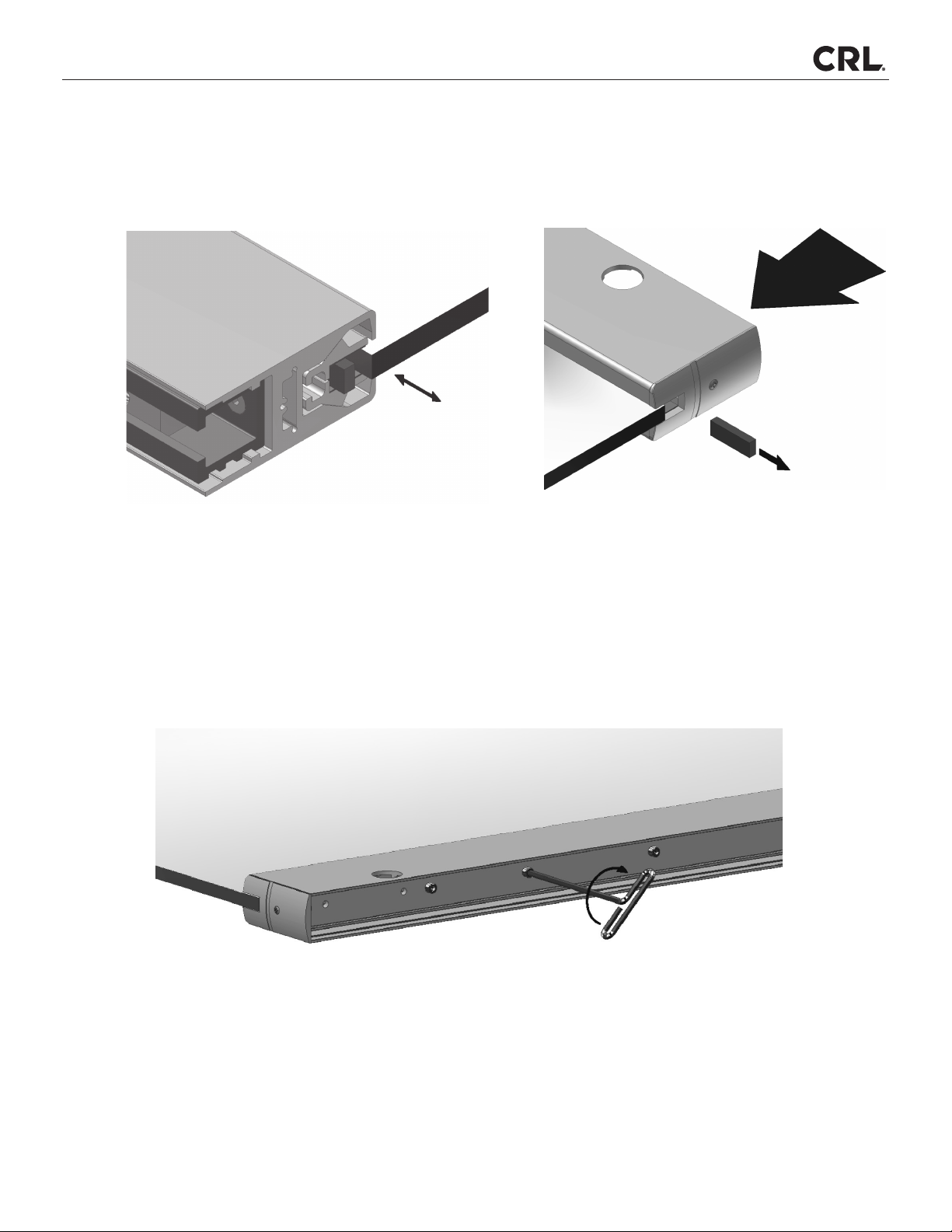
4. Remove End Cap to gain access to the two (2 mm) Allen Set Screws located in the end of the locking mechanism.
Back the Allen Set Screws out until tips have cleared the threads for the Cylinder or Thumbturn. Thread the Cylinders
or Cylinder/Thumbturn that have been chosen for the application through the prefabrication hole in the sides of the
Door Rail and into the lock mechanism. Be sure the 1/8" (3 mm) Spacer Rings are on the Cylinder Thumbturn before
doing this.
5. Once the Cylinders are properly seated, position the small round turning portion of the Cylinder or Thumbturn in the
3 or 9 o'clock horizontal position, depending on which side of the door they are on. The small turning portion should
always face to the opposite end of the Wall Panel Rail. Tighten the two (2 mm) Allen Set Screws to secure the Cylinders
in the correct position. Check to see that the Cylinder/Thumbturn on each side of the Door Rail operates freely before
attaching the End Cap.
NOTE:
There are three different types
of Cylinder's that can be used:
Keyed Cylinder: Cat. No. DRA10
Thumbturn: Cat. No. DRA22
Dummy Cylinder: Cat. No. DRA30
3 o'clock
Position
Assemble Wall Panels (Continued)

INTELLI-TRACK™ SPS SYSTEM
P. 16
C.R. Laurence Co., Inc. • 2503 E. Vernon Ave., Los Angeles, CA 90058 •1.800.421.6144 •crlaurence.com
PLAN VIEW - TOP RAILS
ELEVATION OF TOP RAILS - FROM OUTSIDE
TOP RAIL #2
47.7
2.6
TOP RAIL #1
2.6
Install the Sliding Wall Panels into the Track
1. Remove the Roller Access Splice, which is typically located in front of the first Parking Area Track intersection.
Consult CPP for location.
2. Starting with Panel #1, install a pair of Intelli-Track™ Roller Assemblies into the SPS Track through the
roller-access opening.
Refer to the CPP for proper orientation of the Tracking Rollers of each Intelli-Track™Roller Assembly before installing.
The programming of the Movable Wall Panels is determined by the orientation of the Rollers and must match the CPP.
This is the key element in determining how the Wall Panel is routed by the SPS intersections.

INTELLI-TRACK™ SPS SYSTEM
P. 17
C.R. Laurence Co., Inc. • 2503 E. Vernon Ave., Los Angeles, CA 90058 •1.800.421.6144 •crlaurence.com
NOTE: Care should be taken to protect the finished flooring from possible damage while hanging the
movable Wall Panels. Do not use protective materials under the Wall Panels that are more than
1/4" (6.4) thick, as this makes hanging the Panels difficult.
INSTALL SLIDING WALL PANELS INTO THE TRACK
1. The top Wall Panel Rail (WPR) End Caps are not installed at the factory, but are included in the WPR box.
The End Caps should not be installed onto the top WPR until the Panels are hung and adjusted. Rotate the Support
Block until the set screw is facing outward. Lift one end of the Wall Panel until aligned and push the Support Block
into the WPR. Repeat this process for both ends of the WPR. The Roller Assemblies are set to the minimum floor
clearance adjustment at the factory. This can be verified by seeing that the pendant bolt is flush with the bottom of
the Support Block. This should provide adequate clearance between the floor and Wall Panel for movement.
Support Block

INTELLI-TRACK™ SPS SYSTEM
P. 18
C.R. Laurence Co., Inc. • 2503 E. Vernon Ave., Los Angeles, CA 90058 •1.800.421.6144 •crlaurence.com
1. Slide the #1 Wall Panel to its proper location as indicated on the CPP. Position the Panel against the wall or pivoting
door's edge. Examine the vertical and horizontal gaps and adjust as required.
Adjusting the Sliding Wall Panels
2. Slide the Intelli-Track™Roller Assembly in-line with the Wall Panel Rail (WPR) until the distance from the WPR's
ends (without the End Cap) to the center of the pendant bolt equals 2-3/8" (60) or matches a custom dimension
given on the CPP. Tighten the Lateral Adjustment Locking-nut with a 7/8" open-end wrench to lock the Roller
at this location. The weight of the Wall Panel is now fully supported by the Track. CAUTION: Do not attempt to
slidetheWallPaneluntilthisstepiscompleted.WhenyourstmovethePanel,makesuretocheckoor
clearance throughout the entire opening as you move the Panel, and be aware at all times where the open
splice is located in the Upper Track.
2-3/8"
(60)
Install Sliding Wall Panels into the Track (Continued)

INTELLI-TRACK™ SPS SYSTEM
P. 19
C.R. Laurence Co., Inc. • 2503 E. Vernon Ave., Los Angeles, CA 90058 •1.800.421.6144 •crlaurence.com
3. When desired clearances are attained, using a 3/16" Hex Drive Socket or T-Handle Hex Tool, tighten the Set
Screw located at the end of the Support Block in a clockwise rotation until locked against the Pendant Bolt.
Now re-tighten the Lateral Adjustment Locking Nuts to lock the Rollers at this location.
4. Repeat steps from Page 16, Step 2 for each Sliding Wall Panel.
ADJUSTING THE SLIDING WALL PANELS (CONTIUNED)
2. Further adjustment of panels, loosen the Lateral Adjustment Locking Nut with a 7/8" open-end wrench, and rotate
the Pendant Bolt Height Adjustment Nut to set the floor clearance gap at 1/4" (6.4) depending on field conditions.
CAUTION: The gap between the Track and top of Wall Panel Rail must not exceed 1-9/16" (39.7).
Adjust 1/8" (3.2) vertical gap from top to bottom.
Pendant Bolt height Adjustment Nut
Lateral Adjustment Locking-Nut

INTELLI-TRACK™ SPS SYSTEM
P. 20
C.R. Laurence Co., Inc. • 2503 E. Vernon Ave., Los Angeles, CA 90058 •1.800.421.6144 •crlaurence.com
.
After all Sliding Wall Panels have been attached to the Top Track, re-install the Roller Access Splice that was removed
in.
1. Move the Panel nearest to the parking area to the parking area's double Track entrance. Working with the Roller
Assembly that first enters the parking area, loosen the Lateral Adjustment Locking Nut on this end only.
Carefully move the Wall Panel into the parking area until it comes to rest. Adjust the position of the Intelli-Track™
Roller Assemblies laterally until both Pendant Bolts are centered in the Track slots (important step for smooth
operation), and retighten the Lateral Adjustment Locking Nut.
2. Repeat step 1for all of the Sliding Wall Panels.
Re-install the Roller Access Splice
Adjust Roller Spacing for the Parking Area
Table of contents
Other C.R. Laurence Indoor Furnishing manuals

Popular Indoor Furnishing manuals by other brands

Regency
Regency LWMS3015 Assembly instructions

Furniture of America
Furniture of America CM7751C Assembly instructions

Safavieh Furniture
Safavieh Furniture Estella CNS5731 manual

PLACES OF STYLE
PLACES OF STYLE Ovalfuss Assembly instruction

Trasman
Trasman 1138 Bo1 Assembly manual

Costway
Costway JV10856 manual


