manuals.online logo
Brands
  1. Home
  2. •
  3. Brands
  4. •
  5. CAB
  6. •
  7. Industrial Electrical
  8. •
  9. CAB 3100 User manual

CAB 3100 User manual

This manual suits for next models

1

Popular Industrial Electrical manuals by other brands

Murata GRM0335C1E3R9BA01 Series Reference sheet

Murata

Murata GRM0335C1E3R9BA01 Series Reference sheet

ARCAIR N6000 Automatic System Safety and operating instructions

ARCAIR

ARCAIR N6000 Automatic System Safety and operating instructions

Murata GRM31CR61E106MA12 Series Reference sheet

Murata

Murata GRM31CR61E106MA12 Series Reference sheet

Murata GQM2195C2A9R1CB01 Series Reference sheet

Murata

Murata GQM2195C2A9R1CB01 Series Reference sheet

MFJ MFJ-918 quick start guide

MFJ

MFJ MFJ-918 quick start guide

Abtech HVJB Series Installation, operation & maintenance instructions

Abtech

Abtech HVJB Series Installation, operation & maintenance instructions

Murata GRM0335C1H8R1DA01 Series Reference sheet

Murata

Murata GRM0335C1H8R1DA01 Series Reference sheet

SAF-HOLLAND CBX 5415.5 Installation and operation manual

SAF-HOLLAND

SAF-HOLLAND CBX 5415.5 Installation and operation manual

Eaton Ulusoy HMH24-04 user manual

Eaton

Eaton Ulusoy HMH24-04 user manual

Murata GJM0335C1E4R4BB01 Series Reference sheet

Murata

Murata GJM0335C1E4R4BB01 Series Reference sheet

Newlong NP-7H NSTRUCTION MANUAL/PARTS LIST

Newlong

Newlong NP-7H NSTRUCTION MANUAL/PARTS LIST

Stahl 8575/12 operating instructions

Stahl

Stahl 8575/12 operating instructions

SI Pegasus installation instructions

SI

SI Pegasus installation instructions

Murata GRM1555C1H2R7CA01 Seies Reference sheet

Murata

Murata GRM1555C1H2R7CA01 Seies Reference sheet

Murata GRM0225C1E6R4BA03 Series Reference sheet

Murata

Murata GRM0225C1E6R4BA03 Series Reference sheet

Cooper Power Systems VXE15 Installation and operation instructions

Cooper Power Systems

Cooper Power Systems VXE15 Installation and operation instructions

S&C Vista SD manual

S&C

S&C Vista SD manual

Murata GRM0335C2A7R3CA01 Series Reference sheet

Murata

Murata GRM0335C2A7R3CA01 Series Reference sheet

manuals.online logo
manuals.online logoBrands
  • About & Mission
  • Contact us
  • Privacy Policy
  • Terms and Conditions

Copyright 2025 Manuals.Online. All Rights Reserved.

Edition 10/03
Blow Applicator with Swing Cylinder
Type 3100 / Type 3100H
Part-No. 5535914 / 5537966
Operating Instructions
Blow Applicator with Swing Cylinder
2 cab - Produkttechnik GmbH & Co KG
Gesellschaft für
Computer- und Automations-
Bausteine mbH & Co KG
cab-Produkttechnik GmbH & Co KG
Postfach 19 04 D-76007 Karlsruhe
Wilhelm-Schickard-Straße 14 D-76131 Karlsruhe
Telefon 0721 / 66 26-0
Telefax 0721 / 66 26-249
copyright by cab / 900 8146 / xxx / xx
Angaben zu Lieferumfang, Aussehen, Leistung, Maßen und Gewicht entsprechen unseren Kenntnissen zum Zeitpunkt der
Drucklegung. Änderungen sind vorbehalten.
All specifications about delivery, design, performance and weight are given to the best of our current knowledge and are
subject to change without prior notice.
Blow Applicator with Swing Cylinder
cab - Produkttechnik GmbH & Co KG 3
Table of Contents
Copyright ......................................................................................................................... 2
Table of Contents ............................................................................................................ 3
1. Product Description ....................................................................4
Function .................................................................................................................. 4
Technical Data ........................................................................................................ 4
2. Equipment Supplied....................................................................5
3. Safety Instructions ...................................................................... 6
4. Installation ...................................................................................7
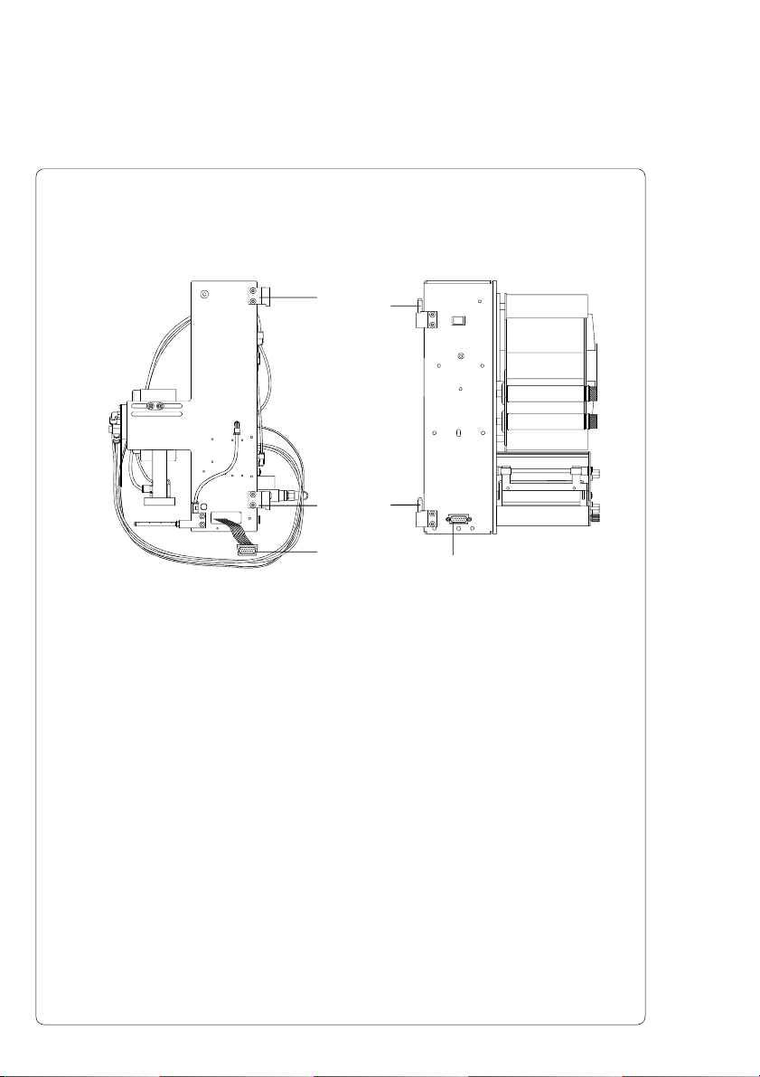
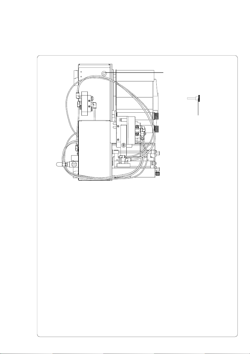
Installing the Blow Applicator on the Apollo ........................................................... 7
Installing the Blow Applicator on the Hermes ........................................................ 8
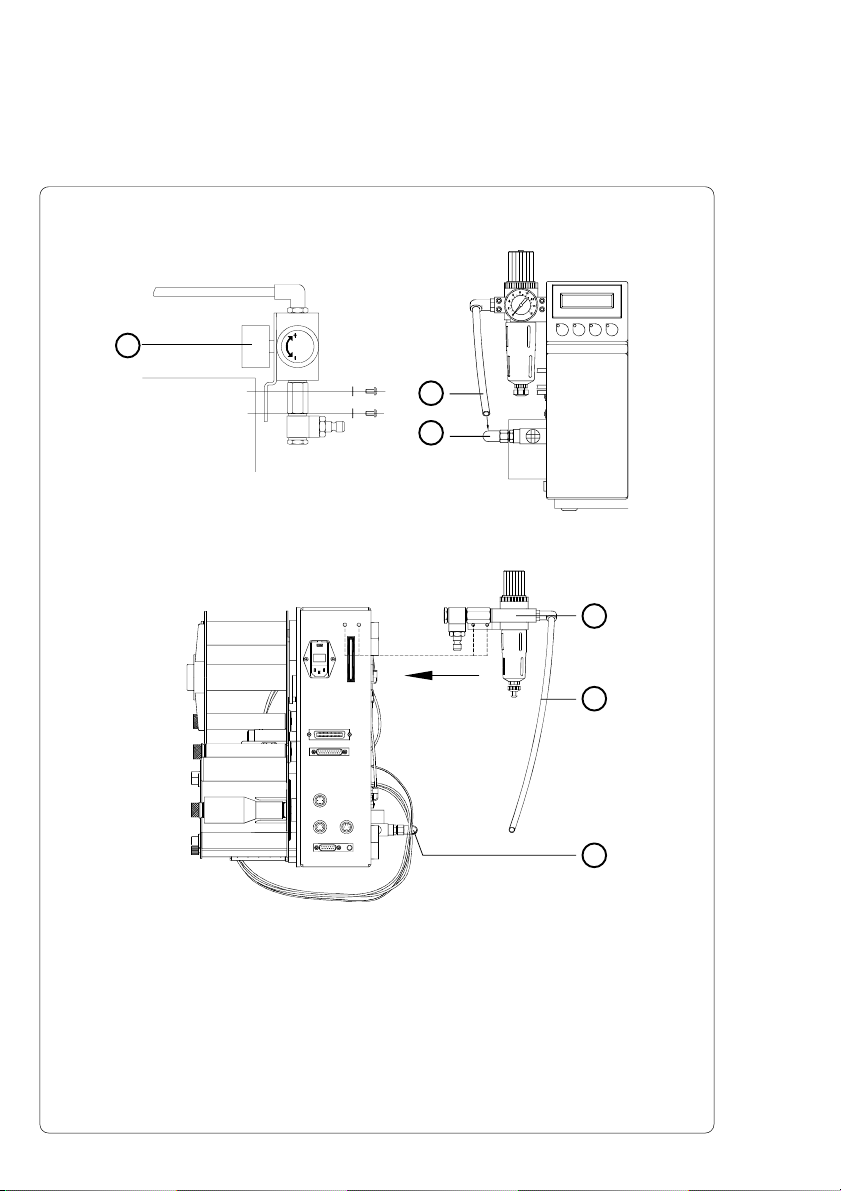
Installing the Service Unit .................................................................................... 10
Connections ......................................................................................................... 11
5. Adjustments ............................................................................... 12
5.1.Mechanical Adjustments ...................................................................................... 12
Angle of the Pad in the Starting Position ............................................................. 12
Adjusting the Level and the Sides of the Cylinder Unit on the Apollo ................. 13
Adjusting the Level and the Sides of the Cylinder Unit on the Hermes .............. 14
Tuning the Blow Tube .......................................................................................... 15
5.2.Pneumatic Adjustments ....................................................................................... 16
Control Valves ...................................................................................................... 16
Throttle Valves at the Cylinder ............................................................................. 17
Throttle Valves at the Manifold ............................................................................ 18
5.3.Selection of the Operation Mode ........................................................................ 19
Operation Mode 'Printing / Labelling' ................................................................... 19
Operation Mode 'Labelling / Printing - Waiting in the Starting Position' .............. 19
Operation Mode 'Labelling / Printing - Waiting in the Labelling Position' ............ 19
Function of the Pre-dispense Key ....................................................................... 20
Setting the Operation Mode and Delay Times..................................................... 22
Print Info Display .................................................................................................. 24
6. Operation .................................................................................. 25
Appendix A - PLC-Interface
Appendix B - Error Messages
Appendix C - Function of the LED of the Applicator Electronics
Index
EC-Conformity Declaration
Blow Applicator with Swing Cylinder
4 cab - Produkttechnik GmbH & Co KG
1. Product Description
Function
The Blow Applicator with Swing Cylinder is an extra device to use with
label printers for automatically applying the printed label onto the
product.
The applicator is equiped with a swing cylinder. This makes it possible
to apply the labels at vertical areas. In the case of use the applicator
at a label printer Apollo it is also possible to apply upward.
The labels are transferred with a pad, which swings between the two
positions, starting position and labelling position, by a compressed-air
driven pneumatic cylinder.
In the starting position, the label is picked up from the printer.
The position of the pad in the starting position is signalized by a
sensor. The label is removed from the carrier ribbon directly at the
dispense edge of the printer. It is sucked on the pad by a vacuum via
drillings at the bottom of the pad. For support, the label is also blown
against the pad with an air current coming from a blow tube. The
correct transfer from the label is controlled by a vacuum sensor.
Next, the pad is moved into the labelling position, which is confirmed
by another sensor (labelling position sensor). Here, the label is blown
onto the product by blow air from the pad.
While the pad is moving back into the starting position, the vacuum
sensor controls whether the label has been removed from the pad.
Specially adapted pads can be used for different label sizes.
The control unit of the applicator is connected with the printer on its
SPI interface using the peripheral connector of the printer.
For operation in a network system the applicator's PLC
(programmable logic control) interface with potential free inputs and
outputs can be used.
Technical Data
Apollo Hermes
Label width : 12-112 mm 10-112 mm
Label height : 12-70 mm 10-80 mm
Air pressure : 5 bis 6 bar 5 bis 6 bar
Turning angle
Swing Cylinder : 115° (forward) 115° (forward)
205° (upward)
Blow Applicator with Swing Cylinder
cab - Produkttechnik GmbH & Co KG 5
Fig. 2 Equipment Supplied
2. Equipment Supplied
1-Blow Applicator with Swing Cylinder Type 3100
for the Transfer Printer Apollo
incl. 4 Cylinder-head Screws
4 Washers
4 Spring Washers
incl. Blow Pad Unit (customized)
- Pad
- Blow Tube
2-Blow Applicator with Swing Cylinder Type 3100H
for the Transfer Printer Hermes
incl.2 Hinges
4Screws
1 Knurled Screw
incl. Blow Pad Unit (customized)
- Pad
- Blow Tube
3 - Service Unit (Option)
incl. 2 Screws
2 Washers
Other options on request !
31 2
Blow Applicator with Swing Cylinder
6 cab - Produkttechnik GmbH & Co KG
3. Safety Instructions
CAUTION !
Make sure that the printer is disconnected from the power supply
and the valve at the service unit as well as the shutoff valve at
the applicator are closed, while installing the delivered
components !
CAUTION !
In operation, moving parts are easily accessible. Therefore, keep
long hair, loose clothes, and jewellery distant.
Before any manipulations in those areas, close the shutoff valve !
CAUTION !
Do not try to manipulate or repair parts that are not described in
the manuals of the blow applicator or the printer !
Blow Applicator with Swing Cylinder
cab - Produkttechnik GmbH & Co KG 7
Installing the Blow Applicator on the Apollo
13
1
2
1
4. Installation
Fig. 4a Installation of the Blow Applicator on the Apollo
1. Dismantle the casing of the manifold (2) by loosening the screws,
two on the left and one on the right.
2. Fasten the applicator at the front of the Apollo using the four
supplied screws (1) including the washers.
3. Plug the connector (3) of the applicator's electronic system in the
peripheral port of the Apollo.
4. Reassemble the casing of the manifold.
Blow Applicator with Swing Cylinder
8 cab - Produkttechnik GmbH & Co KG
Installing the Blow Applicator on the Hermes
2
2
1. Fasten the two hinges (2) included in the equipment on the
Hermes using the supplied screws.
2. Hang the applicator with its two hinges (1) into the hinges (2) of
the Hermes.
3. Turn the applicator towards the Hermes as far as necessary to
plug the connector of the applicator-electronics into the
peripheral connector for cab-applicators on the front of the
printer.
4. Contact the connector (3) of the applicator-electronics to the
peripheral connector (4) of the Hermes.
1
1
3
4
Fig. 4b Installation of the Blow Applicator on the Hermes
Blow Applicator with Swing Cylinder
cab - Produkttechnik GmbH & Co KG 9
Fig. 4c Fastening the Blow Applicator
5. Attach the applicator on the Hermes by screwing the knurled
screw (2) into the hole (1).
2
1
Blow Applicator with Swing Cylinder
10 cab - Produkttechnik GmbH & Co KG
2
3
1
2
3
1
Installing the Service Unit
Fig. 4d Installation of the Service Unit on the Apollo
Fig. 4e Installation of the Service Unit on the Hermes
1. Fasten the service unit (1) at the back of the Apollo and/or the
Hermes using the washers and the screws .
2. Insert the tube of the service unit (2) into the push-in-T-fitting (3)
at the external blow valve.
Insert tube firmly.