Cable AML ITX21-100 Manual

Cable AML
Installation
and
Maintenance
Manual
Indoor Broadband Transmitter
Model: ITX21-100

INSTALLATION AND
MAINTENANCE MANUAL
for
Indoor Broadband Transmitter
Model: ITX21-100
Cable AML, Inc.
3427 W. Lomita Boulevard
Torrance, California 90505 USA
TEL 310 517-8888 or 702 363-5660
FAX 310 517-8555 or 702 363-2960
Copyright ©2004 Cable AML, Inc.
IM4030013-1 Rev – 20040713

Indoor Broadband Transmitter – ITX21-100
IM4030013-1 Rev – i
TABLE OF CONTENTS
Section Page
1.0 INTRODUCTION...................................................................................................... 1
2.0 CIRCUIT DESCRIPTION.......................................................................................... 7
2.1 Upconverter Section.......................................................................................................7
2.2 Power Amplifier Chains..................................................................................................7
2.3 Power Supply Assembly.................................................................................................8
2.4 Diagnostic Circuits .........................................................................................................8
2.5 On-Delay Timer Assembly .............................................................................................8
3.0 INSTALLATION ....................................................................................................... 9
3.1 Unpacking ......................................................................................................................9
3.2 Location..........................................................................................................................9
3.3 Input Voltage Requirements...........................................................................................9
3.4 Operating and Diagnostic Connections..........................................................................9
4.0 OPERATION.......................................................................................................... 13
4.1 Output Level Setting.....................................................................................................13
4.2 Ambient Conditions......................................................................................................14
4.3 Thermal Sensor Switch................................................................................................14
5.0 MAINTENANCE AND TROUBLESHOOTING....................................................... 15
5.1 Maintenance.................................................................................................................15
5.2 External Troubleshooting .............................................................................................15
5.3 Internal Troubleshooting ..............................................................................................16
6.0 SPECIFICATIONS ................................................................................................. 19

Indoor Broadband Transmitter – ITX21-100
IM4030013-1 Rev – ii
LIST OF ILLUSTRATIONS
Figure Page
1 ITX21-100 Broadband Transmitter..................................................................2
2 ITX21-100 Component Layout........................................................................ 3
3 ITX21-100 Block Diagram...............................................................................5
4 DC Diagnostics Switch Positions. ................................................................... 8
5 Front Panel Connection Points......................................................................10
6 Rear Panel Connection Points...................................................................... 11
7 Output Level Adjustment...............................................................................13
LIST OF TABLES
Table Page
1 Typical Channel Loading for ITX21-100 Input/Output Levels........................ 10

Indoor Broadband Transmitter – ITX21-100
IM4030013-1 Rev – 1
1.0 INTRODUCTION
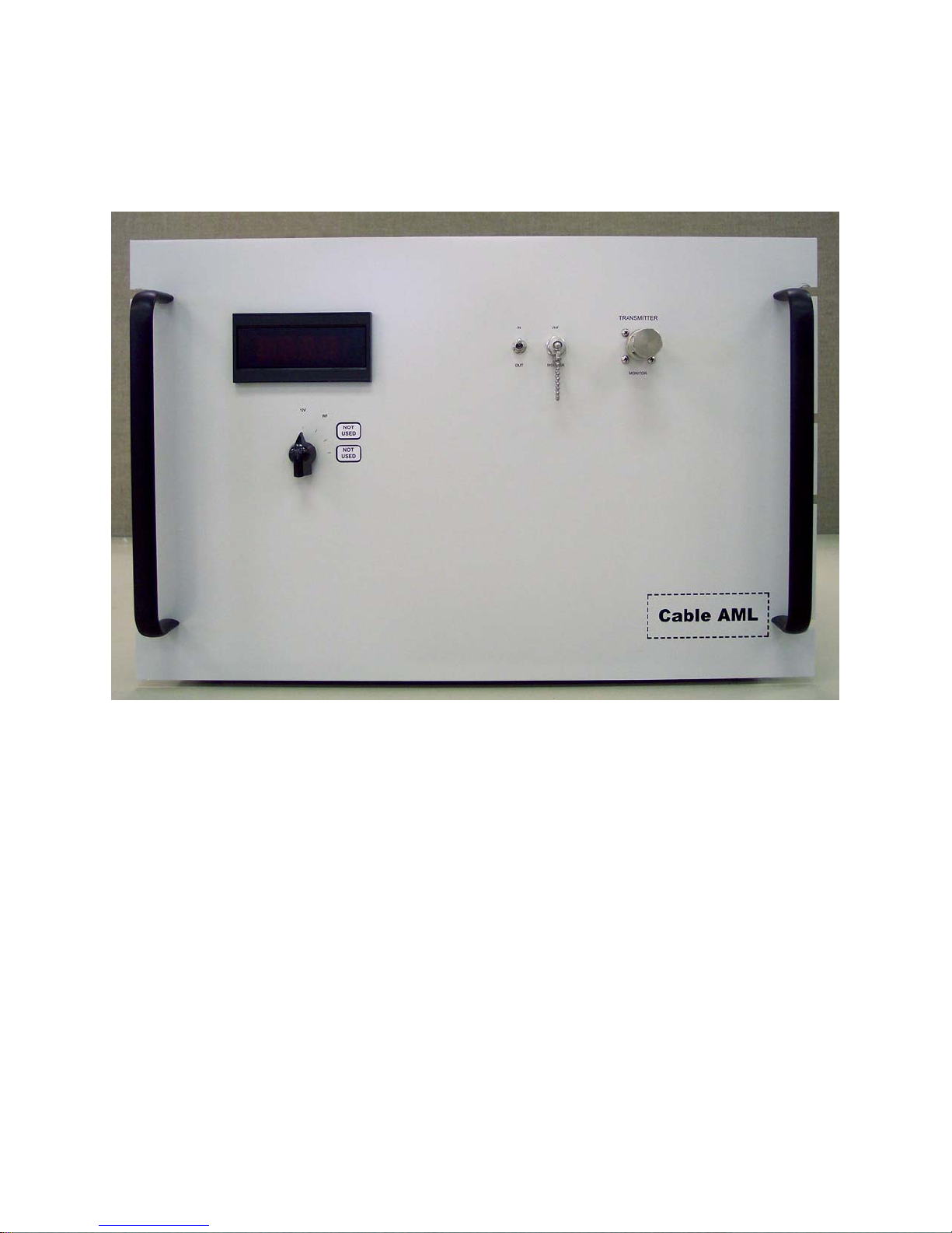
The ITX21-100 shown in Figure 1 is a solid-state broadband transmitter that converts a
VHF input signal of 119 MHz to a microwave signal of 2.159 GHz.
The ITX21-100transmitter consists of the following assemblies (refer to Figure 2).
1. Upconverter – for converting the incoming VHF signal to microwave. The
upconverter section contains all components necessary for upconversion, i.e. local
oscillator, mixer, as well as band-pass and notch filters.
2. Power Amplifier – The amplification is accomplished with minimum distortion by a
state of the art linearised Gallium Arsenide FET microwave power amplifier. The
power amplifier is protected from failure due to overheating by an internal
temperature sensor. The sensor circuit automatically switches off the amplifier D.C.
power when the amplifier temperature exceeds 158 degrees F (70 degrees C).
3. Power supply system – The microwave modules are powered from a +12 VDC
switching power supply. The local oscillator is powered from a +12 VDC linear
power supply. A 24 VDC power supply powers the downconverter. A +5 VDC
voltage regulator is used to for the power amplifier’s TTL circuit.
4. Monitoring and Diagnostic Circuits – Depending on the configuration of the
compact transmitter, the input and output can be continuously monitored without
interruption of service with a standard TV set or a field strength meter by means of a
front panel dual function coaxial connector. Diagnostic DC voltages can also be
continuously monitored via a front panel meter with a selectable switch or a rear
panel multi-pin connector.
5. On-Delay Timer Assembly – Upon start-up of the compact transmitter, a binary
counter is used to delay voltage to the power amplifier. This gives the +12 VDC
switching power supply time to stabilize.
The ITX21-100transmitter can be equipped to operate on either 120 or 240 VAC at 50 to
60 Hz. This option is specified by customer request, and each unit is shipped according to
this specification.
Complete specifications are listed in Section 6.0.

Indoor Broadband Transmitter – ITX21-100
IM4030013-1 Rev – 2
Figure 1. ITX21-100 Broadband Transmitter.

Indoor Broadband Transmitter – ITX21-100
IM4030013-1 Rev – 3
On- Dela
y
Timer Circuit
Upconverter
Test-Point
+12 VDC
Power Supply
Output
Circulator
Local Oscillator
Filter Local
Oscillator Meter
VHF Processor
+12 VDC Fan
(Power Amp
Underneath)
+24 VDC
Power Supply
Figure 2. ITX21-100 Component Layout.

Indoor Broadband Transmitter – ITX21-100
IM4030013-1 Rev – 4
This Page Intentionally Left Blank.)

Indoor Broadband Transmitter – ITX21-100
IM4030013-1 Rev –– 5
J1
COAX F FILTER BPF
87110-005 87112-013
FILTER NOTCH
42106-001
VHF PROCESSOR
COAX F
COAX N
TTL
+12V BUSS
-40
RF MONITOR
2150-2162 MHz
VHF MONITOR
116-128 MHz
+12VDC BUSS
GND BUSSPS1
PS2
PWR
INSERT DOWN
CONVERT
MMDS DOWN CONVERTER
CUSTOMER SUPPLIED
LNA
87194-000
G=12 dB
+5V(TTL)
AC HIGH
AC LOW
AC GND
120 or 240 VAC
DPM
DC DIAGNOSTICS
RF OUTPUT
2150-2162 MHz
33.0 dBm/Ch 2 Channels AVG PWR
VHF INPUT
116-128 MHz
25 dBmV/Ch 2 Channels
RF MON
+12V
83517-001
83520-004
TIMER
RELAY
INPUT
OUTPUT
12
3
ISOLATOR
87103-221
+12VDC +5VDC
+12VDC
+12VDC
12
3
ISOL
87103-222 LOCAL OSCILLATOR
87225-013
MIXER
87202-019
G= -8 dB
F1
10A
UPCONVERTER MONITOR
TERM
DIR COUPLER
87102-210
RF MON
RF SAMPLE
@ 1.7A
@ 25A
AC INPUT
AC TO DPM
FRONT PANEL CONTROL
POWER AMP
87161-003
G=56 dB
+12V BUSS
87102-230
DIR COUPLER
-10
87102-210
DIR COUPLER
LO MONITOR
84311-010
10 dB Pad
PS3
83501-008
+24VDC
0.7A
+24V
FAN
83401-050
Relay
81202-001
87331-101
CIRCULATOR
87099-001
TERMINATION
84211-007
PANEL MOUNT
84122-008
12V
com
1NO
2
SWITCH
RESISTOR
2278
MHz
FILTER BPF
87151-013
ECN # REV DATE
SHEET OF
SCALE
DRAWING NO.
DATEAPPROVED BY:
REV.
SIZE
DATEDRAWN BY:
TITLE
COMPANY
CABLE AML, INC. Torrance, California, USA
1 1
HCK 04-15-04
4030013-1
ITX21-100 BLOCK DIAGRAM
-- --
Figure 3. ITX21-100 Block Diagram.

Indoor Broadband Transmitter – ITX21-100
IM4030013-1 Rev –– 6
(This Page Intentionally Left Blank)

Indoor Broadband Transmitter – ITX21-100
IM4030013-1 Rev – 7
2.0 CIRCUIT DESCRIPTION
The ITX21-100Transmitter consists of the following circuits or modules:
1. Upconverter Section
2. Power Amplifier
3. Power Supply System
4. Monitoring and Diagnostic Circuits - connectors and switches.
5. On-Delay Timer Assembly.
In addition, microwave isolators and filters are used as necessary to ensure the stability
and purity of transmitted signals.
2.1 Upconverter Section
The Upconverter Section is comprised of the following major functional circuits or
modules:
1. Hybrid Local Oscillator
2. Upconverter/ Mixer
3. Filter Assembly
Hybrid Local Oscillator – The local oscillator consists of a crystal oscillator, frequency
multiplier, and a band pass filter all encapsulated in solid 6061-T6 aluminum. The output
of the local oscillator provides pump power to the signal upconverter. The local oscillator is
powered by +12 VDC.
Upconverter Mixer – The translation from VHF to microwave frequencies takes place
here. The mixer is also called an "upper sideband upconverter". The desired output of
the upconverter is a signal at a frequency, which is the sum of the local oscillator, and
VHF input frequencies. The upconverter also generates unwanted signals which have to
be filtered out, among them the "lower sideband", LO leakage, and others.
Filter Assembly – There are two filters. The group band-pass filter is tuned to pass the
upper sideband. The notch filter is tuned to attenuate the local oscillator leakage without
affecting the output signal.
2.2 Power Amplifier Chains
The power amplifier is a state of the art linearised device with a 1 dB compression point of
100-Watts average (50 dBm). The design incorporates four stages of amplification in
series, each incorporating pre-matched GaAs (Gallium Arsenide) power modules. The
total gain is approximately 40 dB. In addition to the microwave circuits, the amplifier
includes DC voltage regulator circuits, output RF monitoring circuits, and TTL-actuated
power-off capabilities. The TTL circuit uses a 5VDC voltage regulator to turn the power
amplifier’s voltage regulators on or off. +5VDC to the power amplifier will activate the TTL
circuit, causing the amplifier to turn itself off.

Indoor Broadband Transmitter – ITX21-100
IM4030013-1 Rev – 8
2.3 Power Supply Assembly
Two +12 VDC and one +24 VDC power supplies are used to provide the DC voltage. A
+12 VDC linear power supply is used to provide power to the internal downconverter and
Local Oscillator. A 5 VDC regulator is only used for the TTL switch for the power amplifier.
The MDS downconverter is powered by a 24 VDC power supply. A +12 VDC switching
power supply is used to power everything else in the compact transmitter.
2.4 Diagnostic Circuits1
The ITX21-100transmitter has several connectors and switches.
Connectors - There are two monitor connectors on the front panel. The transmitter’s input
and output at VHF can be viewed at the “VHF MONITOR” port on the front panel.
Selection is by a toggle switch, which energizes a 12 VDC coaxial relay. The “INPUT”
position selects a sample of the VHF input directly. The “OUTPUT” position selects the
VHF spectrum downconverted from a sample of the microwave output of the power
amplifier. The downconversion is performed by an internal MDS downconverter with the
same LO as the compact transmitter. The transmitters output at microwave can be viewed
at the “RF MONITOR” port on the front panel. The signal is a sample of the power
amplifiers output thru a 40 dB coupler.
DC Voltage Diagnostics – DC voltage diagnostic signals can be read using the built- in
meter on the front panel. The functions available are shown below:
12V RF
NOT USED
NOT USED
READING FROM 11.5V to 12.5V
READING FROM 0.2V to 1.0V
1. +12 VDC of power supply, volts
2. RF detector of power amp, volts
Figure 4. DC Diagnostics Switch Positions.
Power "On/Off" Switch Panel – The power amp switch applies +5VDC to the power
amplifier’s TTL circuit, which shuts down the power amplifier.
2.5 On-Delay Timer Assembly
A relay and binary counter is used to delay power to the amplifier. This is so the +12 VDC
power supply has a chance to stabilize upon start up of the Transmitter. The counter is set
for an 8 second delay upon start up of the transmitter.
1See Data Manual for nominal values of diagnostic signals.

Indoor Broadband Transmitter – ITX21-100
IM4030013-1 Rev – 9
3.0 INSTALLATION
3.1 Unpacking
Inspect shipment for obvious damage then carefully check for other possible shipping
damage such as bent or loose connections that may result in signal leakage. If any
damage is suspected, notify Cable AML and the shipper before proceeding with
installation of the equipment.
Check the packing list against the parts shipped and verify that the correct material has
been received. Communicate any discrepancies to Cable AML immediately.
3.2 Location
All transmitters should be installed in an area with adequate ventilation to provide the
necessary airflow into the unit. The rubber feet installed on the chassis are for bench
testing convenience.
Each rack mountable chassis unit (to be installed by customer) should be assembled in
rack with at least 6 inches free space above them. This allows removal of hole plugs in
the top covers for access to the adjusting screws of the VHF processor module.
A support bar has been provided to help with the weight of the transmitter should it be
installed in a rack. It should be placed near the rear of the transmitter.
3.3 Input Voltage Requirements
Cable AML transmitters can be equipped to operate on either 120 or 240 VAC at either 50
or 60 Hz. This option is specified by customer request, and each unit is shipped
according to this specification.
3.4 Operating and Diagnostic Connections
Figure 6 shows the locations of connectors on the rear and front panels of the transmitter.
Operating Connections
•RF Output – The transmitter's output connector on the rear panel is type N
coaxial, to which the output cable to the transmit antenna is connected.
•VHF Input – The transmitter's input connector on the rear panel is type F
female, to which the VHF inputs are connected.
AC Power connections – This unit is equipped with an AC power cord that is wired for
single-phase operation. It is necessary to attach a plug to the power cord before putting
the unit into operation. It is important that the following color code be followed when wiring
up the transmitter!!
The BLACK or BROWN wire is HOT or MAIN lead.
The WHITE or BLUE wire is the NEUTRAL lead.
The GREEN or GREEN/YELLOW is the GROUND or EARTH lead.

Indoor Broadband Transmitter – ITX21-100
IM4030013-1 Rev – 10
Table 1. Typical Channel Loading for ITX21-100 Input/Output Levels2
Number Of
Channels Input Level To Transmitter Output Level From
Transmitter
9 31.5 dBmV/Channel 27.5 dBm/Channel
12 30.0 dBmV/Channel 26.0 dBm/Channel
18 28.0 dBmV/Channel 24.0 dBm/Channel
24 26.0 dBmV/Channel 22.0 dBm/Channel
30 25.0 dBmV/Channel 21.0 dBm/Channel
Diagnostic Connections
Diagnostic connections, not essential to the normal operation of the transmitter, are made
at the front panel of the transmitter.
RF Diagnostics – A type N connector is provided on the front panel for the RF monitor
point. The location is shown in Figure 5.
VHF Input/Output Test Point – VHF input and output signal test point “F” connector is
provided on the front panel. A toggle switch is used to switch between input and output
VHF signals.
Figure 5. Front Panel Connection Points.
2 See Data Manual for actual values.

Indoor Broadband Transmitter – ITX21-100
IM4030013-1 Rev – 11
Figure 6. Rear Panel Connection Points.

Indoor Broadband Transmitter – ITX21-100
IM4030013-1 Rev – 12
(This Page Intentionally Left Black.)

Indoor Broadband Transmitter – ITX21-100
IM4030013-1 Rev – 13
4.0 OPERATION
The ITX21-100 transmitter requires no adjustments when used in the configuration
recommended in the Data Manual. To properly operate the transmitter, simply apply the
required AC power and input signal. The ITX21-100 transmitter can be equipped to
operate on either 120 or 240 VAC at 50 or 60 Hz. This option is specified by customer
request, and each unit is shipped according to these specifications.
4.1 Output Level Setting
The output power for each ITX21-100 Transmitter Unit depends entirely on the input level.
If the input level at VHF is higher than the recommended value, both the output power
and the CTB (Composite Triple Beat) distortion will increase. For every one dB of higher
input level there will be one dB of higher output power and two dB higher distortion.
CONSEQUENTLY, IT IS NOT RECOMMENDED TO CHANGE OR ADJUST THE
TRANSMITTER OUTPUT LEVELS UNLESS THERE ARE SIGNIFICANT CHANGES IN
THE NUMBER OF INPUT CHANNELS OR OTHER SYSTEM PARAMETERS.
A Microwave Power Meter or Spectrum Analyzer is required to set the Output Level. It
should be connected to the transmitter output monitor connector on the front panel.
The output level can then be set by adjusting the VHF Processor Module's level set
attenuator labeled "VHF ADJ" for the required output level required by the system design.
The adjusting screw is shown in Figure 7. If a power meter is not available, the
transmitter output monitor reading can be used in conjunction with a table provided with
the transmitter performance data sheets provided in the Data Manual.
Observe the output of the transmitter with the spectrum analyzer. Using the "VHF ADJ”
set the channel levels to the desired level. An individual channel that is out of line with the
others must be adjusted at its source.
P/N 42104-002
VHF
ADJ
VHF IN
VHF OUT
VHF LEVEL
ADJUSTING
SCREW
Cable AML
Figure 7. Output Level Adjustment.

Indoor Broadband Transmitter – ITX21-100
IM4030013-1 Rev – 14
4.2 Ambient Conditions
The ITX21-100 transmitter is designed to operate with no external cooling devices.
Internal cooling fans maintain component temperatures at desirable levels when ambient
conditions are in the range specified in Section 6.0 - Specifications.
4.3 Thermal Sensor Switch
To protect the power amplifier from overheating due to fan failure or excessive ambient
temperature, an internal temperature sensor automatically cuts off DC input power to the
power amplifier when the temperature exceeds a factory set threshold of 158°F (70°C). If
the cause of overheating is fan failure, the failed unit should be replaced prior to applying
power.

Indoor Broadband Transmitter – ITX21-100
IM4030013-1 Rev – 15
5.0 MAINTENANCE AND TROUBLESHOOTING
5.1 Maintenance
Maintenance is not normally required for the ITX21-100 after initial installation. However
input and output power levels should be measured periodically and adjustments made if
necessary.
The output power level should be measured and adjusted as described in Section 4.0 of
this manual. The VHF input levels should be verified before making significant
adjustments in the transmitter. If the VHF input level is correct and the transmitters output
cannot be set properly, external troubleshooting is necessary as described in the next
section.
5.2 External Troubleshooting
In the event of low or no output from the transmitter, first verify the following:
1. Verify the AC power input by checking the fan on the transmitter for motion. If not
operating then check the line fuse on the back panel.
2. Frequency and level of the VHF input.
•Incorrect input frequencies may produce output frequencies that are unable
to pass through the two filters or the power amplifier.
If these items are found acceptable, check the VHF Transmitter Monitor output:
1. With the selector switch in the INPUT position, the output will be a replica of the
VHF input signals, but about 20 dB lower. If the Transmitter Monitor INPUT
selection produces low or no output, recheck item #1 above.
2. With the selector switch in the OUTPUT position, the output should be a replica of
the VHF input signals, but about 5-10 dB higher. If the Transmitter Monitor OUTPUT
selection produces low or no output, check the DC diagnostics on the front panel
meter.
DC Diagnostics (Figure 4 lists expected values for each function)
NO +12 VDC. Internal troubleshooting is necessary.
If source tuning does not eliminate the transmitter output malfunction then internal
troubleshooting is necessary.

Indoor Broadband Transmitter – ITX21-100
IM4030013-1 Rev – 16
5.3 Internal Troubleshooting
Remove the cover of the transmitter.
WARNING
Internal troubleshooting requires that:
¾Power remains on.
¾Transmitter cover is removed.
1CONTACT WITH LINE VOLTAGE CAN BE FATAL! 1
It is recommended that internal troubleshooting be limited to personnel skilled in
maintenance of microwave transmitters or receivers.
IF IT IS NECESSARY TO REPLACE COMPONENTS, THE REPLACEMENT OF PARTS
SHOULD BE DONE WITH THE EXTERNAL AC POWER DISCONNECTED.
a
Internal Quick Check.
A quick check should show that the fan is operating and the power amplifier and its power
supply are warm to the touch.
Lack of +12 VDC
If internal trouble shooting is required due to lack of +12 VDC in the external DC
diagnostic test then check for internal +12 VDC on the terminal strips. If either of these
voltages is missing, first disconnect the wires from the power supply output terminals and
recheck the voltage.
If the power supply voltage with no load is not +12 VDC then the power supply is defective
and should be replaced.
If the voltage is normal, the load on the power supply is too high causing the supply to go
into crowbar and shut down. At this point, examine the wiring harness for an obvious
wiring fault. If no fault is found, then one of the modules supplied by that power supply is
shorted internally and should be replaced. To identify the module remove the DC power
wire for each module one at a time from the terminal block until the DC power bus is
restored to normal.
Table of contents
Other Cable AML Transmitter manuals
Popular Transmitter manuals by other brands

Siemens
Siemens SITRANS P310 with HART Compact operating instructions

Halemeier
Halemeier S-Mitter installation instructions

Me
Me BELL-215 TX V3 instruction manual

Matchmaster
Matchmaster 20MM-LT10L operating manual

Kobold
Kobold SEN-98 operating instructions

Wilcoxon
Wilcoxon iT150 Series Installation and operating manual