Cable AML ITX02-2000 Instruction Manual

Proprietary
FCC ID: JXZITX02-2000
Type Acceptance Report 6/20/03 55
Proprietary
12.0 USER’S MANUAL

Cable AML
Installation
and
Maintenance
Manual
Indoor Broadband Transmitter
Model: ITX02-2000

INSTALLATION AND
MAINTENANCE MANUAL
for
Indoor Broadband Transmitter
Model: ITX02-2000
Cable AML, Inc.
3427 W. Lomita Boulevard
Torrance, California 90505 USA
TEL 310 517-8888 or 702 363-5660
FAX 310 517-8555 or 702 363-2960
Copyright ©2003 Cable AML, Inc.
IM402513-10 20030619

Indoor Broadband Transmitter – ITX02-2000
i
IM402513-10 Rev –
TABLE OF CONTENTS
Section Page
1.0 INTRODUCTION ...................................................................................................... 1
2.0 CIRCUIT DESCRIPTIONS ....................................................................................... 7
2.1 MMDS Transmitter Driver...............................................................................................7
2.2 Power Amplifier Chains ..................................................................................................8
2.3 Power Supply Assembly.................................................................................................8
2.4 Diagnostic Circuits..........................................................................................................8
2.5 On-Delay Timer Assembly..............................................................................................9
2.6 Internal Downconverter ..................................................................................................9
3.0 INSTALLATION...................................................................................................... 11
3.1 Unpacking.....................................................................................................................11
3.2 Location ........................................................................................................................11
3.3 Input Voltage Requirements .........................................................................................11
3.4 Operating and Diagnostic Connections ........................................................................11
4.0 OPERATION .......................................................................................................... 17
4.1 Output Level Setting .....................................................................................................17
4.2 Ambient Conditions ......................................................................................................18
4.3 Thermal Sensor Switch ................................................................................................18
5.0 MAINTENANCE & TROUBLESHOOTING ............................................................ 19
5.1 Maintenance .................................................................................................................19
5.2 External Troubleshooting..............................................................................................19
5.3 Internal Troubleshooting...............................................................................................19
6.0 SPECIFICATIONS.................................................................................................. 21

Indoor Broadband Transmitter – ITX02-2000
ii
IM402513-10 Rev –
LIST OF ILLUSTRATIONS
Figure Page
Figure 1. ITX02-2000 Broadband Transmitter. ........................................................... 2
Figure 2. Dial and Expected Readings........................................................................ 3
Figure 3. MMDS Rack Monitor Panel. ......................................................................... 3
Figure 4. ITX02-2000 Block Diagram........................................................................... 5
Figure 5. Driver Chassis Component Layout. .......................................................... 10
Figure 6. MMDS Installation Block Diagram............................................................. 12
Figure 7. AC Input Wiring Diagram. .......................................................................... 13
Figure 8. Driver Chassis Front And Rear Panels. .................................................... 14
Figure 9. ITX02-2000 Rack (Front and Back). ........................................................... 15
Figure 10. Output Level Adjustment. ....................................................................... 17

Indoor Broadband Transmitter – ITX02-2000
1
IM402513-10 Rev –
1.0 INTRODUCTION
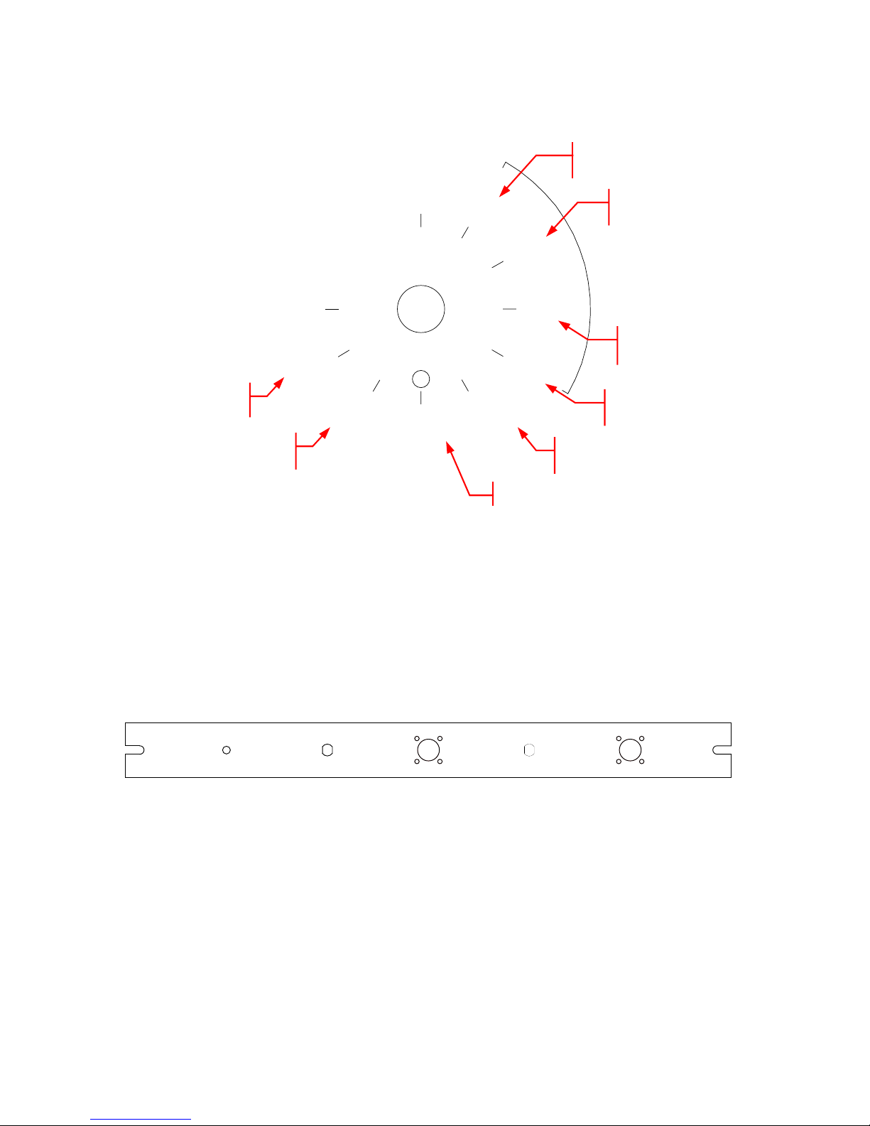
The ITX02-2000 shown in Figure 1 is a solid-state broadband transmitter, which converts a
VHF, input signal of 222 to 408 MHz to a microwave signal of 2.5 to 2.686 GHz.
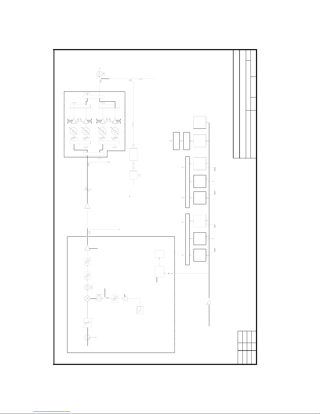
The ITX02-2000 transmitter consists of eight assemblies:
1. Driver Chassis - for converting the incoming VHF signal to microwave. The Driver
chassis contains all components necessary for upconversion, i.e. local oscillator, mixer,
as well as bandpass and notch filters.
2. Power Amplifier - input signal is amplified to a maximum level consistent with the
Carrier to Composite Triple Beat (C/CTB) specification by state of the art GaAs FET
microwave power amplifiers in a parallel, power-quadrupling configuration. The power
amplifiers are protected from failure due to overheating by an internal temperature
sensor. The sensor circuit automatically switches off the amplifier when the amplifier
temperature exceeds 167 degrees F (75 degrees C).
3. Power supply system - a redundant 12 VDC system consisting of three current
sharing modules with hot-plug replacement capability. Each module has an 84 Amp
capability. Only two modules are required to run the system, making the third one a
built-in spare. A +5 VDC voltage regulator is used to power the power amplifier TTL
circuit. The Driver chassis and fans are powered by the +12 VDC power supply.
4. Monitoring and Diagnostic Circuits - To facilitate operational monitoring and
diagnostics of: VHF input, VHF output, Driver RF output, and Transmitter RF output.
Diagnostic DC voltages can also be continuously monitored with the built-in meter on
the Meter Panel.
5. On-Delay Timer Assembly - Delays power to the amplifier. This is done to avoid a
big current surge when the transmitter is first turned on.
6. Internal Downconverter - For ease of monitoring the Transmitter’s output, a
downconverter has been mounted inside. The downconverter takes a sample of the
output and converts it to VHF. This VHF output signal can then be measured with a
Field Strength Meter or a TV monitor.
The ITX02-2000 transmitter can be equipped to operate on either 120 or 240 VAC at 50 or 60
Hz. This option is specified by customer request, and each unit is shipped according to this
specification.
Complete specifications are listed in Section 6.0.

Indoor Broadband Transmitter – ITX02-2000
2
IM402513-10 Rev –
Figure 1. ITX02-2000 Broadband Transmitter.

Indoor Broadband Transmitter – ITX02-2000
3
IM402513-10 Rev –
12V
DRIVER
IPS1
IPS2
IPS3
AMP 1
RF
AMP 2
RF
12V
TX
AMP 3
RF
AMP 4
RF
TX RF
Reading From
–85 to -200V
Reading From 11.5
to 12.5V
Reading From
0.7 to 1.7V
Reading From
0.7 to 1.7V
Reading From
0.7 to 1.7V
Reading From –85 to -200V
Reading From
–85 to -200
V
Reading From
–
85 to -200V
Figure 2. Dial and Expected Readings.
LOCAL
OSCILLATOR INPUT VHF DRIVER OUTPUT VHF TRANSMITTER
MONITOR MONITOR MONITOR MONITORMONITOR
Figure 3. MMDS Rack Monitor Panel.

Indoor Broadband Transmitter – ITX02-2000
4
IM402513-10 Rev –
(This Page Intentionally Left Blank.)

Indoor Broadband Transmitter – ITX02-2000
5
IM402513-10 Rev –
METER PANEL 1
30 dB
METER PANEL 2
TEMP +
RF MONITOR
TEMP +
RF MONITOR
TEMP +
RF MONITOR
TEMP +
RF MONITOR
0
90 0
90
0
90 0
90
0
90 0
90
120/240 VAC
50/60 Hz
F1-1 AMP SLO-BLO
87202-019
UPCONVERTER
12 VDC
POWER
SUPPLY
POWER
SUPPLY
#1
12 VDC BUS
POWER AMPS
10 dB
(FRONT PANEL)
DRIVER CHASSIS
TO TTL-AMP
VHF TEST POINT
FRONT PANEL
10 dB
RF OUT
2500 TO
2698 MHz
RF TEST POINT
(FRONT PANEL)
87225-013
LOCAL OSCILLATOR
2278.0 MHz
MONITOR
+12 VDC
(METER PANEL)
87112-013
NOTCH
FILTER
87110-0014
BANDPASS
FILTER
VHF IN
222 - 420 MHz
FAN
METER
PANEL
POWER
SUPPLY
#2
POWER
SUPPLY
24 VDC
POWER SUPPLY
5 VDC
REGULATOR
ON-DELAY
TIMER
40 dB
PARALLEL POWER NETWORK
RF OUT
2500-2686 MHz
31 CHANNELS
34 dBm/CH
POWER
SUPPLY
#3
TX MONITOR
(FRONT PANEL)
DOWN CONVERTER
CONNECTION POINT
(FRONT PANEL)
POWER
SUPPLY
#4
12 VDC BUS
POWER AMPS
POWER
SUPPLY
#5
POWER
SUPPLY
#6
FANSFANS
TTL
+12 VDC
TTL
TTL
+12 VDC
TTL
+12 VDC
LO TEST POINT
87102-220
20 dB
+12 VDC
87116-004
PUMP AMP
87151-013
PUMP FILTER
86101-020
20 dB 87194-000
GAIN = 12 dB
63515-001 83401-001
ITX02 DRIVER 402013-06
87194-000
GAIN = 12 dB
30 dB
PWR
INSERT
DOWN
CONVERT
10 dB
87226-001
421060-01
VHF PROCESSOR
ECN # REV DATE
SHEET OF
SCALE
DRAWING NO.
DATEAPPROVED BY:
REV.
SIZE
DATEDRAWN BY:
TITLE
COMPANY
CABLE AML, INC. Torrance, California, USA
1 1
--
HCK 02-12-03
402513-10
ITX02-2000 GP MMDS
-- --
Figure 4. ITX02-2000 Block Diagram.

Indoor Broadband Transmitter – ITX02-2000
6
IM402513-10 Rev –

Indoor Broadband Transmitter – ITX02-2000
7
IM402513-10 Rev –
2.0 CIRCUIT DESCRIPTIONS
The ITX02-2000 Transmitter consists of the following circuits or modules:
1. MMDS Transmitter Driver
2. Power Amplifier
3. Power Supply System (three +12 VDC current sharing modules and one +24 VDC
power supply)
4. Monitoring and Diagnostic Circuits - connectors and switches.
5. On-Delay Timer Assembly.
6. Internal Downconverter.
In addition, microwave isolators and filters are used as necessary to ensure the stability and
purity of transmitted signals.
2.1 MMDS Transmitter Driver
The MMDS Driver is comprised of the following major functional circuits or modules:
1. Local Oscillator (LO)
2. Upconverter/Mixer
3. Filter Assembly
4. Microwave Low Noise Amplifier
5. DC Diagnostics
6. Power Supply
Local Oscillator (LO)
The microwave local oscillator is a crystal oscillator and frequency multiplier encapsulated in a
single enclosure. The output of the LO provides pump power to the signal upconverter. The LO
is powered by a +12 VDC power supply. The long-term frequency stability of the oscillator is 5
parts per million per year.
Upconverter Mixer
The translation from VHF to microwave frequencies takes place here. The mixer is also called
an "upper sideband upconverter". The desired output of the upconverter is a signal at a
frequency, which is the sum of the local oscillator and VHF input frequencies. The upconverter
also generates unwanted signals which have to be filtered out, among them the "lower
sideband", LO leakage, and others.
Filter Assembly
There are two filters. The group bandpass filter is tuned to pass the upper sideband. The notch
filter is tuned to attenuate the local oscillator leakage without affecting the output signal.

Indoor Broadband Transmitter – ITX02-2000
8
IM402513-10 Rev –
Microwave Low Noise Amplifier
A Low Noise Amplifier accomplishes the amplification with minimum distortion.
DC Diagnostics Circuit
Certain test points in the transmitter can be monitored externally at the Remote Monitor output
multi-pin connector on the front panel. These DC diagnostics are connected to the output
connector through a signal conditioning circuit. The signal conditioning circuit is a network of
resistors that provides short circuit protection for the transmitter diagnostic sources. The output
connector is designed for use with diagnostic test boxes such as the Cable AML DTB - 1, the
WRM-2, or the RM-2A. The test points and corresponding connector pin connections are shown
in the Transmitter Block Diagram.
Power Supply
The power supply for the MMDS Driver is +12 VDC.
2.2 Power Amplifier Chains
The power amplifier consists of four GaAs FET microwave power amplifier that amplifies the
input signal to a maximum level consistent with the Carrier to Composite Triple Beat (C/CTB)
specification. The power amplifier is protected from failure due to overheating by an internal
temperature sensor. The sensor circuit automatically switches off the amplifier input power
when the amplifier temperature exceeds 167°F (75°C). The power amplifiers are arranged in a
quadruple power configuration which results in an overall IP3 increase of 5 dB. The gain of the
amplifiers is 56 dB with an IP3 of 69.5 dBm. The amplifiers have a TTL circuit, which enables
the user to shut down the amplifiers for testing purposes. +5VDC = “ON”
2.3 Power Supply Assembly
The transmitter has a 12 VDC redundant power supply system consisting of three current-
sharing modules with hot-plug replacement capability. Each module has an 84 Amp capability.
Only two modules in each mainframe are needed to run the transmitter. A 24 VDC power
supply powers the internal downconverter and also supplies voltage to a 5 VDC voltage
regulator, which is used with the Transistor-Transistor-Logic (TTL) of the power amp. A
separate +12 VDC power supply is used for the Driver.
2.4 Diagnostic Circuits1
The ITX02-2000 transmitter has several connectors and switches.
Connectors - there are "test point" and "monitor" output connectors on the front panel. Their
position in the circuitry is shown in Figure 3.
1See Data Manual for nominal values of diagnostic signals.

Indoor Broadband Transmitter – ITX02-2000
9
IM402513-10 Rev –
DC Voltage Diagnostics - DC voltage diagnostic signals can be read using the built- in meter
on the front panel. The functions available on the front panel is shown below:
1. +12 VDC of Driver power supply (volts)
2. +12 VDC buss (volts)
3. Current monitor #1, see Data manual for scale factor
4. Current monitor #2, see Data manual for scale factor
5. Current monitor #3, see Data manual for scale factor
6. RF Detector at Amp #1 (volts)
7. RF Detector at Amp #2 (volts)
8. RF Detector at Amp #3 (volts)
9. RF Detector at Amp #4 (volts)
10. RF Detector TX Output (volts)
Amplifier Power "On/Off" Switch Panel - this panel is located behind a "blank" front panel as
shown in Figure 1. For access to this panel, the "blank" front panel must be removed. The
switches are intended to cut off power to the amplifiers. Their position in the circuitry can be
seen in the Figure 4.
2.5 On-Delay Timer Assembly
A set of relay’s and timer’s is used to delay power to the amplifier. This is so the +12 VDC
power supply has a chance to stabilize upon start up of the Transmitter.
2.6 Internal Downconverter
For ease of monitoring the Transmitter output, a downconverter has been mounted inside the
Transmitter. The downconverter takes a sample of the output and converts it to VHF. This VHF
output signal can then be measured with a Field Strength Meter or a TV monitor.

Indoor Broadband Transmitter – ITX02-2000
10
IM402513-10 Rev –
Amplifier
Power
Supply
Local
Oscillator
Pump
Amp
Filters Upconverter
V
HF
Processor
Figure 5. Driver Chassis Component Layout.

Indoor Broadband Transmitter – ITX02-2000
11
IM402513-10 Rev –
3.0 INSTALLATION
3.1 Unpacking
Inspect shipment for obvious damage then carefully check for other possible shipping damage
such as bent or loose connections that may result in signal leakage. If any damage is
suspected, notify Cable AML and the shipper before proceeding with installation of the
equipment.
!!!!! CAUTION !!!!! CAUTION !!!!! CAUTION !!!!!
Transmitters shipped installed in a standard EIA Enclosed Equipment Relay Rack may have
foam blocks inserted between modules inside the rack to protect the unit during transportation.
These blocks must be removed before operation otherwise they will impede the flow of cooling
air and may affect the performance of the transmitter.
Check the packing list against the parts shipped and verify that the correct material has been
received. Communicate any discrepancies to Cable AML immediately.
3.2 Location
All transmitters should be installed in an area with adequate ventilation to provide the necessary
airflow into the unit.
Position floor-mounted enclosed equipment racks on a flat surface with enough space at the
rear to swing open the access door.
3.3 Input Voltage Requirements
Cable AML transmitters can be equipped to operate on either 120 or 240 VAC at either 50 or 60
Hz. This option is specified by customer request, and each unit is shipped according to this
specification. Some 220/240 VAC units can be connected directly to 220/240 VAC power mains
and some utilize step-down transformers furnished with the unit. If the local power mains are
220/240 VAC and the unit is shipped with a step-down transmitter, connect the mains to
the transformer only!
3.4 Operating and Diagnostic Connections
Figure 4 shows the locations of connectors on the rear and front panels of the transmitter.
Operating Connections
• RF Output - The transmitter's output connector on the rear panel is type N coaxial, to
which the output cable to the transmit antenna is connected.
• RF Input - The transmitter's input connector on the rear panel is type F female, to
which the VHF inputs are connected.

Indoor Broadband Transmitter – ITX02-2000
12
IM402513-10 Rev –
MMDS TX-2000
TRANSMITTER
VHF SIGNAL
AC POWER
RF
OUT
VHF
IN
Figure 6. MMDS Installation Block Diagram.
AC Power Connections
This unit is equipped with an AC power cord that is wired for single-phase operation. It is
necessary to attach a plug to the power cord before putting the unit into operation.
For operating in three phase current please note that the circuit breaker WILL NOT be used, the
4 jumpers on the AC input terminal block must be removed, and The AC wires must be
connected as shown in Figure 7.

Indoor Broadband Transmitter – ITX02-2000
13
IM402513-10 Rev –
PHASE 1
PHASE 2
PHASE 3
PHASE 1
PHASE 1
PHASE 2
PHASE 2
PHASE 3
PHASE 3
INPUT AC
(GROUND
OR EARTH)
INPUT AC
(NEUTRAL)
INPUT AC
(HOT OR
MAIN)
TO CIRCUIT BREAKER
LINE SIDE
FROM CIRCUIT
BREAKER
LOAD SIDE
PHASE 1
PHASE 2
PHASE 3
PHASE 1
PHASE 1
PHASE 2
PHASE 2
PHASE 3
PHASE 3
GROUND
or
EARTH
(GREEN or
GREEN/YELLOW)
NEUTRAL
(WHITE or
BLUE)
HOT or
MAIN
(BLACK or
BROWN)
GROUND
or
EARTH
(GREEN or
GREEN/YELLOW)
NEUTRAL
(WHITE or
BLUE)
HOT or
MAIN
(BLACK or
BROWN)
INPUT AC, PHASE 1 (GROUND)
INPUT AC, PHASE 1 (NEUTRAL)
INPUT AC, PHASE 1 (HOT)
INPUT AC, PHASE 2 (GROUND)
INPUT AC, PHASE 3 (GROUND)
INPUT AC, PHASE 2 (NEUTRAL)
INPUT AC, PHASE 3 (NEUTRAL)
INPUT AC, PHASE 2 (HOT)
INPUT AC, PHASE 3 (HOT)
THREE PHASE
WIRING
SINGLE PHASE
WIRING
Figure 7. AC Input Wiring Diagram.

Indoor Broadband Transmitter – ITX02-2000
14
IM402513-10 Rev –
Diagnostic Connections
Diagnostic connections, not essential to the normal operation of the transmitter, are made at the
front panel of the transmitter.
• RF Diagnostics - Two RF test point output "N" connectors for Driver RF output and
Transmitter Monitor output are provided on the front panel. The locations in the
circuitry are shown in Figure 5
• XO and VHF Input Test Points - Crystal oscillator (XO) monitor, VHF input and output
signal test point "F" connectors are provided on the front panel.
VHF IN VHF TEST POINT
MMDS TRANSMITTER DRIVER
RF OUT
REMOTE MONITOR
Cable AML
FUSE 1A
SLO-BLO
AC INPUT
120 VAC or
240 VAC
50/60 Hz
Figure 8. Driver Chassis Front And Rear Panels.

Indoor Broadband Transmitter – ITX02-2000
15
IM402513-10 Rev –
Meter
Panel
Driver
12 VDC
@ 84 A
Power
Supplies (x3)
Blowe
r
Figure 9. ITX02-2000 Rack (Front and Back).
Table of contents
Other Cable AML Transmitter manuals
Popular Transmitter manuals by other brands

Siemens
Siemens SITRANS P310 with HART Compact operating instructions

Halemeier
Halemeier S-Mitter installation instructions

Me
Me BELL-215 TX V3 instruction manual

Matchmaster
Matchmaster 20MM-LT10L operating manual

Kobold
Kobold SEN-98 operating instructions

Wilcoxon
Wilcoxon iT150 Series Installation and operating manual