Cablematic 3.5" User manual

3.5” 4 Bay RAID enclosure
User Guide
Include
☆Getting Started & Notice
☆About the Enclosure
☆HDD Installation Guide
☆RAID Mode Guide
☆Hard Drive Formatting Guide
☆Power Synchronization
Important: All data will be deleted on each
HDD Mode change. Back up HDD(s) before
adjusting RAID Switch.
4 Bay MULTI HDD BOX User Guide
1
1. Getting Started & Notice
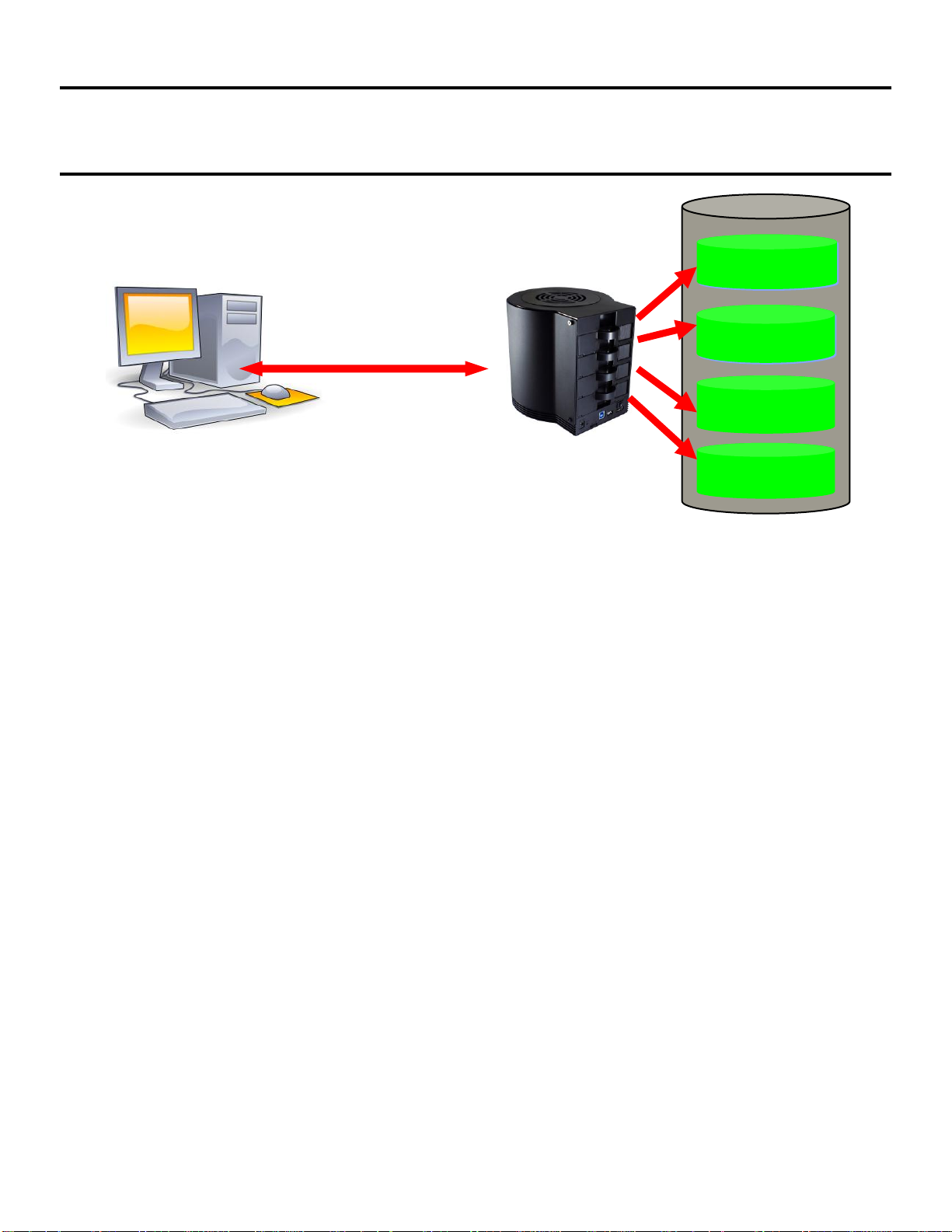
This 4-bay RAID enclosure allows users flexibly operate their HDDs with different modes.
When using eSATA connection, eSATA host controller on the computers must be Port
Multiplier (PM) capable. Otherwise, only a single drive will be presented (HDD 1). No such
limitation by USB connection.
-USB 3.0 connection and backward compatible to USB 2.0
-SATA-II interface hosts SATA –I, II, III HDD(s)
-HDD capacity supports up to 3TB in GPT format, W7/Vista, Linux, MAC
-Windows XP can’t support 3TB HDD
Notice:
1. Please read the manual carefully before you begin using this product.
2. This product operates between 0oC to 40oC with a relative humidity between 5% to 80 %.
Be sure the unit is operating in a well ventilated environment.
3. Do not block any of the ventilation holes on the product in order to retain the best heat
dissipation efficiency possible.
4. Do not place any liquids or chemical hazards near the product.
5. This product operates using a 12V/DC output, 100V~240V/AC input power adapter. Do
not use any other types of AC/DC rating’s adapter which differs to the mentioned
specifications. Doing so will severely damage the product.
6. The power adapter should be well ventilated and not be covered by any object.
7. HDDs must be well secured and fixed to the HDD-tray before sliding the HDD-tray into
the Multi-HDD frame.
HDD1
HDD2
USB 3.0
eSATA
HDD3
HDD4
4 Bay MULTI HDD BOX User Guide
2
2. About the Enclosure
HardwareOverview________________________________________
Power DC input
Receptor for the provided Power Adapter
- 12V DC, 100-240V AC, 50-60Hz
- 4 Amp (by minimum requirement)
PC connection interface
USB 3.0
Connect USB 3.0 Cable to computer
eSATA
Connect eSATA Cable to computer
Note: When connecting eSATA and USB3.0 to the PC at the same time, eSATA connectivity will be
prioritized
FAN Speed Control
Rotatory Knob
Tuning the FAN speed to from minimum to maximum speed to
allow efficient ventilation, and backward to reduce noise level.
LED Indication:
Power LED
Green
ON : Power on
OFF: Power off
HDD 1 LED
Blue
ON : HDD inserted
Flash Randomly: Accessing (Read/Write/Rebuild)
Flash Constantly(3Hz): HDD error
OFF: HDD not installed/Removed/sleep mode
HDD 2 LED
Blue
ON : HDD inserted
Flash Randomly: Accessing (Read/Write/Rebuild)
Flash Constantly(3Hz): HDD error
OFF: HDD not installed/Removed/sleep mode
HDD 3 LED
Blue
ON : HDD inserted
Flash Randomly: Accessing (Read/Write/Rebuild)
Flash Constantly(3Hz): HDD error
OFF: HDD not installed/Removed/sleep mode
HDD 4 LED
Blue
ON : HDD inserted
Flash Randomly: Accessing (Read/Write/Rebuild)
Flash Constantly(3Hz): HDD error
OFF: HDD not installed/Removed/sleep mode
4 Bay MULTI HDD BOX User Guide
3
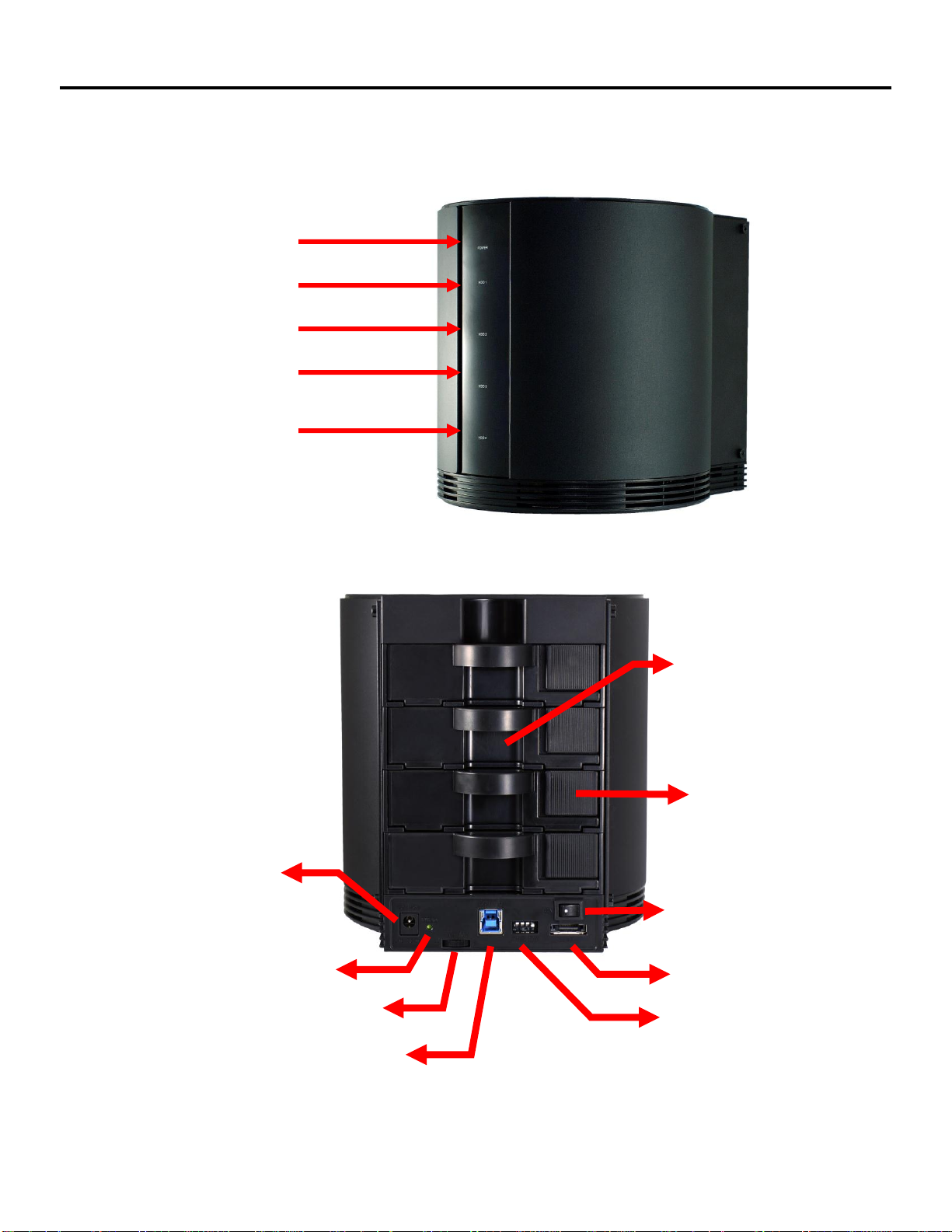
Front / Back View
Power LED
HDD1 LED
HDD2 LED
HDD3 LED
HDD4 LED
Tray lock
Power On/Off
switch
RAID Reset
HDD Tray
Fan Speed Control
eSATA
RAID Mode Switch
USB3.0
Power Jack
(DC12V)

4 Bay MULTI HDD BOX User Guide
4
3. HDD Installation Guide
Step1: Push the Locker to the left to unlock the HDD tray.
Step2: Take out the HDD trays.

4 Bay MULTI HDD BOX User Guide
5
Step3: Paste the HDD pad(s) to the center & inside of the tray(s) ONLY IF the HDD(s)
cannot be stably mounted.
Step4: Install the HDD(s) into the tray(s) and fix 2 screws on both sides per tray. Make sure
screws are firmly fixed to hold the tray(s) and HDD(s) together.

4 Bay MULTI HDD BOX User Guide
6
Step5: Slide HDD trays back to the case.
Step5: Push the Locker to the right to lock the HDD tray.

4 Bay MULTI HDD BOX User Guide
7
4. RAID Mode Guide
RAIDModes
JBOD
Just a bunch of Drives, R/W each HDD independently
Sum of 4 HDD capacity
RAID 0
RAID : R/W on each HDD simultaneously
Capacity: multiply the smallest capacity by 4
RAID 3
RAID: Byte-level striping with dedicated parity
Capacity: multiply the smallest capacity by (4-1)
RAID 5
RAID: Block-level striping with distributed parity
Capacity: multiply the smallest capacity by (4-1)
RAID10
(RAID1)
RAID: mirroring on each HDD simultaneously
Capacity equals to the smallest HDD multiply 2
Note:
1. HDD1/HDD2 create a set of RAID 1: HDD1/2
HDD3/HDD4 create a set of RAID 1: HDD3/4
Two sets (HDD1/2, HDD3/4) create a set of RAID 0
2.When install only two HDDs, the device will perform RAID1
Capacity: Smaller capacity by 1
Normal
Shows 4 individual HDDs
RAIDSwitchsetting:

4 Bay MULTI HDD BOX User Guide
8
Raid Mode Setting
RAID mode setting via RAID switch
1. Power on the case.
2. Check and make sure all HDDs are installed and all HDD LEDs light up.
3. Connect the case to PC via USB or eSATA cable(1 cable only). Make sure HDD LED
light up.
4. Select HDD Mode from below table by adjusting “Raid Switch”, which is located at
the back of the case.
5. Pin and hold “RAID Reset” for 3~5 seconds. Then HDD mode will change according
to the selection.
6. After setting RAID mode, please initialize the HDD again to have the HDD workable.
Please refer to Page.18 for initializing a hard disk.
7. Format HDDs before they are ready to use.
Note:
Refer to Hard Drive Formatting Guide in the below session for detailed
instructions.
After setting the RAID mode, you can look over the JMicron HW RAID Manager
for checking if you have the correct RAID mode.
RAID Reset
RAID Switch
4 Bay MULTI HDD BOX User Guide
9
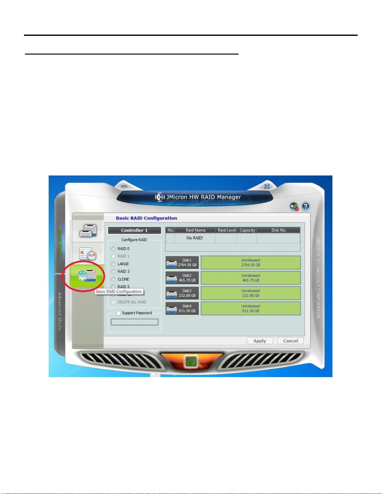
RAID mode Setting via JMicron HW RAID Manager
Note: NO RAID mode setting software for Linux OS.
1. Power on the case.
2. Check and make sure all HDDs are installed perfectly
3. Connect the case to PC via USB or eSATA cable. Make sure all HDD LEDs light
up.
4. Select JMicron HW RAID Manager_Win for Windows OS. Select JMicron_Mac
for Mac OS.
5. Select the Basic RAID Configuration icon under Basic mode for RAID mode
setting.
This manual suits for next models
1
Table of contents


 user manual")


