Bull Escala E5-700 Instruction Manual


ESCALA Power7
Installing the 58/88 PCIe storage enclosure
The ESCALA Power7 publications concern the following models:
- Bull Escala E5-700 (Power 750 / 8233-E8B)
- Bull Escala M6-700 (Power 770 / 9117-MMB)
- Bull Escala M6-705 (Power 770 / 9117-MMC)
- Bull Escala M7-700 (Power 780 / 9179-MHB)
- Bull Escala M7-705 (Power 780 / 9179-MHC)
- Bull Escala E1-700 (Power 710 / 8231-E2B)
- Bull Escala E1-705 (Power 710 / 8231-E1C)
- Bull Escala E2-700 / E2-700T (Power 720 / 8202-E4B)
- Bull Escala E2-705 / E2-705T (Power 720 / 8202-E4C)
- Bull Escala E3-700 (Power 730 / 8231-E2B)
- Bull Escala E3-705 (Power 730 / 8231-E2C)
- Bull Escala E4-700 / E4-700T (Power 740 / 8205-E6B)
- Bull Escala E4-705 (Power 740 / 8205-E6C)
References to Power 755 / 8236-E8C models are irrelevant.
Hardware
May 2012
BULL CEDOC
357 AVENUE PATTON
B.P.20845
49008 ANGERS CEDEX 01
FRANCE
REFERENCE
86 A1 67FH01

The following copyright notice protects this book under Copyright laws which prohibit such actions as, but not limited to, copying,
distributing, modifying, and making derivative works.
Bull SAS 2012
Copyright
Printed in France
Suggestions and criticisms concerning the form, content, and presentation of this book are
invited. A form is provided at the end of this book for this purpose.
To order additional copies of this book or other Bull Technical Publications, you are invited
to use the Ordering Form also provided at the end of this book.
Trademarks and Acknowledgements
We acknowledge the right of proprietors of trademarks mentioned in this book.
The information in this document is subject to change without notice. Bull will not be liable for errors contained herein, or
r incidental or consequential damages in connection with the use of this material.
fo

Contents
Safety notices .................................v
Installing the 58/88 PCIe storage enclosure ....................1
Installing the 58/88 PCIe storage enclosure: Details .................3
Reference information .............................17
Connector locations.................................17
Server connectors ................................17
Model 02E/4B connector locations..........................17
Model 02E/4C connector locations .........................18
Model 31E/1C or 31E/2C connector locations ......................19
Enclosure connectors ...............................20
Model 58/88 connector locations ..........................20
Notices ...................................21
Trademarks ...................................22
Electronic emission notices ..............................22
Class A Notices .................................22
Class B Notices .................................26
Terms and conditions ................................28
iii

iv Power Systems: Installing the 58/88 PCIe storage enclosure

Safety notices
Safety notices may be printed throughout this guide.
vDANGER notices call attention to a situation that is potentially lethal or extremely hazardous to
people.
vCAUTION notices call attention to a situation that is potentially hazardous to people because of some
existing condition.
vAttention notices call attention to the possibility of damage to a program, device, system, or data.
World Trade safety information
Several countries require the safety information contained in product publications to be presented in their
national languages. If this requirement applies to your country, a safety information booklet is included
in the publications package shipped with the product. The booklet contains the safety information in
your national language with references to the U.S. English source. Before using a U.S. English publication
to install, operate, or service this product, you must first become familiar with the related safety
information in the booklet. You should also refer to the booklet any time you do not clearly understand
any safety information in the U.S. English publications.
Laser safety information
The servers can use I/O cards or features that are fiber-optic based and that utilize lasers or LEDs.
Laser compliance
The servers may be installed inside or outside of an IT equipment rack.
v

DANGER
When working on or around the system, observe the following precautions:
Electrical voltage and current from power, telephone, and communication cables are hazardous. To
avoid a shock hazard:
vConnect power to this unit only with the provided power cord. Do not use the provided power
cord for any other product.
vDo not open or service any power supply assembly.
vDo not connect or disconnect any cables or perform installation, maintenance, or reconfiguration
of this product during an electrical storm.
vThe product might be equipped with multiple power cords. To remove all hazardous voltages,
disconnect all power cords.
vConnect all power cords to a properly wired and grounded electrical outlet. Ensure that the outlet
supplies proper voltage and phase rotation according to the system rating plate.
vConnect any equipment that will be attached to this product to properly wired outlets.
vWhen possible, use one hand only to connect or disconnect signal cables.
vNever turn on any equipment when there is evidence of fire, water, or structural damage.
vDisconnect the attached power cords, telecommunications systems, networks, and modems before
you open the device covers, unless instructed otherwise in the installation and configuration
procedures.
vConnect and disconnect cables as described in the following procedures when installing, moving,
or opening covers on this product or attached devices.
To Disconnect:
1. Turn off everything (unless instructed otherwise).
2. Remove the power cords from the outlets.
3. Remove the signal cables from the connectors.
4. Remove all cables from the devices
To Connect:
1. Turn off everything (unless instructed otherwise).
2. Attach all cables to the devices.
3. Attach the signal cables to the connectors.
4. Attach the power cords to the outlets.
5. Turn on the devices.
(D005a)
DANGER
vi Power Systems: Installing the 58/88 PCIe storage enclosure

Observe the following precautions when working on or around your IT rack system:
vHeavy equipment–personal injury or equipment damage might result if mishandled.
vAlways lower the leveling pads on the rack cabinet.
vAlways install stabilizer brackets on the rack cabinet.
vTo avoid hazardous conditions due to uneven mechanical loading, always install the heaviest
devices in the bottom of the rack cabinet. Always install servers and optional devices starting
from the bottom of the rack cabinet.
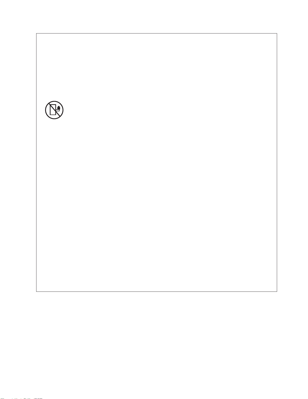
vRack-mounted devices are not to be used as shelves or work spaces. Do not place objects on top
of rack-mounted devices.
vEach rack cabinet might have more than one power cord. Be sure to disconnect all power cords in
the rack cabinet when directed to disconnect power during servicing.
vConnect all devices installed in a rack cabinet to power devices installed in the same rack
cabinet. Do not plug a power cord from a device installed in one rack cabinet into a power
device installed in a different rack cabinet.
vAn electrical outlet that is not correctly wired could place hazardous voltage on the metal parts of
the system or the devices that attach to the system. It is the responsibility of the customer to
ensure that the outlet is correctly wired and grounded to prevent an electrical shock.
CAUTION
vDo not install a unit in a rack where the internal rack ambient temperatures will exceed the
manufacturer's recommended ambient temperature for all your rack-mounted devices.
vDo not install a unit in a rack where the air flow is compromised. Ensure that air flow is not
blocked or reduced on any side, front, or back of a unit used for air flow through the unit.
vConsideration should be given to the connection of the equipment to the supply circuit so that
overloading of the circuits does not compromise the supply wiring or overcurrent protection. To
provide the correct power connection to a rack, refer to the rating labels located on the
equipment in the rack to determine the total power requirement of the supply circuit.
v(For sliding drawers.) Do not pull out or install any drawer or feature if the rack stabilizer brackets
are not attached to the rack. Do not pull out more than one drawer at a time. The rack might
become unstable if you pull out more than one drawer at a time.
v(For fixed drawers.) This drawer is a fixed drawer and must not be moved for servicing unless
specified by the manufacturer. Attempting to move the drawer partially or completely out of the
rack might cause the rack to become unstable or cause the drawer to fall out of the rack.
(R001)
Safety notices vii

CAUTION:
Removing components from the upper positions in the rack cabinet improves rack stability during
relocation. Follow these general guidelines whenever you relocate a populated rack cabinet within a
room or building:
vReduce the weight of the rack cabinet by removing equipment starting at the top of the rack
cabinet. When possible, restore the rack cabinet to the configuration of the rack cabinet as you
received it. If this configuration is not known, you must observe the following precautions:
– Remove all devices in the 32U position and above.
– Ensure that the heaviest devices are installed in the bottom of the rack cabinet.
– Ensure that there are no empty U-levels between devices installed in the rack cabinet below the
32U level.
vIf the rack cabinet you are relocating is part of a suite of rack cabinets, detach the rack cabinet from
the suite.
vInspect the route that you plan to take to eliminate potential hazards.
vVerify that the route that you choose can support the weight of the loaded rack cabinet. Refer to the
documentation that comes with your rack cabinet for the weight of a loaded rack cabinet.
vVerify that all door openings are at least 760 x 230 mm (30 x 80 in.).
vEnsure that all devices, shelves, drawers, doors, and cables are secure.
vEnsure that the four leveling pads are raised to their highest position.
vEnsure that there is no stabilizer bracket installed on the rack cabinet during movement.
vDo not use a ramp inclined at more than 10 degrees.
vWhen the rack cabinet is in the new location, complete the following steps:
– Lower the four leveling pads.
– Install stabilizer brackets on the rack cabinet.
– If you removed any devices from the rack cabinet, repopulate the rack cabinet from the lowest
position to the highest position.
vIf a long-distance relocation is required, restore the rack cabinet to the configuration of the rack
cabinet as you received it. Pack the rack cabinet in the original packaging material, or equivalent.
Also lower the leveling pads to raise the casters off of the pallet and bolt the rack cabinet to the
pallet.
(R002)
(L001)
(L002)
viii Power Systems: Installing the 58/88 PCIe storage enclosure

(L003)
or
All lasers are certified in the U.S. to conform to the requirements of DHHS 21 CFR Subchapter J for class
1 laser products. Outside the U.S., they are certified to be in compliance with IEC 60825 as a class 1 laser
product. Consult the label on each part for laser certification numbers and approval information.
CAUTION:
This product might contain one or more of the following devices: CD-ROM drive, DVD-ROM drive,
DVD-RAM drive, or laser module, which are Class 1 laser products. Note the following information:
vDo not remove the covers. Removing the covers of the laser product could result in exposure to
hazardous laser radiation. There are no serviceable parts inside the device.
vUse of the controls or adjustments or performance of procedures other than those specified herein
might result in hazardous radiation exposure.
(C026)
Safety notices ix

CAUTION:
Data processing environments can contain equipment transmitting on system links with laser modules
that operate at greater than Class 1 power levels. For this reason, never look into the end of an optical
fiber cable or open receptacle. (C027)
CAUTION:
This product contains a Class 1M laser. Do not view directly with optical instruments. (C028)
CAUTION:
Some laser products contain an embedded Class 3A or Class 3B laser diode. Note the following
information: laser radiation when open. Do not stare into the beam, do not view directly with optical
instruments, and avoid direct exposure to the beam. (C030)
CAUTION:
The battery contains lithium. To avoid possible explosion, do not burn or charge the battery.
Do Not:
v___ Throw or immerse into water
v___ Heat to more than 100°C (212°F)
v___ Repair or disassemble
Exchange only with the approved part. Recycle or discard the battery as instructed by local
regulations. (C003a)
Power and cabling information for NEBS (Network Equipment-Building System)
GR-1089-CORE
The following comments apply to the servers that have been designated as conforming to NEBS
(Network Equipment-Building System) GR-1089-CORE:
The equipment is suitable for installation in the following:
vNetwork telecommunications facilities
vLocations where the NEC (National Electrical Code) applies
The intrabuilding ports of this equipment are suitable for connection to intrabuilding or unexposed
wiring or cabling only. The intrabuilding ports of this equipment must not be metallically connected to the
interfaces that connect to the OSP (outside plant) or its wiring. These interfaces are designed for use as
intrabuilding interfaces only (Type 2 or Type 4 ports as described in GR-1089-CORE) and require isolation
from the exposed OSP cabling. The addition of primary protectors is not sufficient protection to connect
these interfaces metallically to OSP wiring.
Note: All Ethernet cables must be shielded and grounded at both ends.
The ac-powered system does not require the use of an external surge protection device (SPD).
The dc-powered system employs an isolated DC return (DC-I) design. The DC battery return terminal
shall not be connected to the chassis or frame ground.
xPower Systems: Installing the 58/88 PCIe storage enclosure

Installing the 58/88 PCIe storage enclosure
Use this overview as a guide to the tasks required for installing the 58/88 PCI Express (PCIe) storage
enclosure (EXP30 Ultra SSD I/O Drawer) into a rack and cabling it to a server.
Procedure
You can use the following table to read about and complete the high-level tasks for installing the 58/88
PCIe storage enclosure.
Table 1. Tasks to install the disk drive enclosure into a rack
Task Where to find associated information
Preinstalled enclosures only
Remove the front and rear shipping brackets.
After you have removed the shipping brackets, go to the
task Review the configuration options for adding the PCIe
storage enclosure to the server.
To remove the front and rear shipping brackets, see step
2 on page 3.
Perform inventory.
Ensure that you have the rails.
Ensure that you have both a Philips-head and flat-head
screwdriver.
Locate the inventory list for your disk drive enclosure,
and verify that you received all of the parts that you
ordered.
Each order contains, at a minimum, the following items:
vLeft and right rack-mounting rails
vMounting screws
vPower supply cables
If your shipment contains parts that are not required to
complete the installation procedure, store those parts
until they are required to be used.
You can also obtain order information from your
marketing representative or IBM®Business Partner.
Verify that you have a rack. You must have a rack installed. If you do not have a rack
installed, see Installing the rack (http://
publib.boulder.ibm.com/infocenter/systems/scope/hw/
topic/p7hbf/installrack.htm).
Prepare to install the disk drive enclosure. To ensure that you have taken all other preparatory steps
to install this disk drive enclosure, see Installing the 5888
in a rack (http://publib.boulder.ibm.com/infocenter/
systems/scope/hw/topic/p7ham/
p7ham_5888_prepare.htm).
Power off the system, if required, to install the disk drive
enclosure.
For requirements and procedures related to shutting
down and powering off the system, see Overview for
I/O expansion units (http://publib.boulder.ibm.com/
infocenter/systems/scope/hw/topic/p7ham/
p7ham_pcistor_concepts.htm).
Determine where to install the disk drive enclosure in
the rack.
For suggestions about how to organize the hardware in
your rack and to assign a location for the disk drive
enclosure, see step 4 on page 4.
1

Table 1. Tasks to install the disk drive enclosure into a rack (continued)
Task Where to find associated information
Mark the location on the rack where the PCIe storage
enclosure will be installed.
If you have a rack-mounting template for the PCIe
storage enclosure, use it to mark the location.
If you do not have a rack-mounting template, see step
4d2 on page 5.
Install the rail assembly in the rack. To install the mounting hardware in the rack, see step 5
on page 6.
Install the PCIe storage enclosure on the rail assembly. To install the PCIe storage enclosure on the rail assembly,
see step 6 on page 8.
Review the configuration options for adding the PCIe
storage enclosure to the server.
To identify the configuration option that you will use
from a list of example configurations, see step 7 on page
11.
Cable the PCIe storage enclosure to the server. To add the PCIe storage enclosure to the system
configuration, see step 8 on page 13
Configure the solid state drives of the PCIe storage
enclosure.
To review serial-attached SCSI (SAS) Redundant Array of
Independent Disks (RAID) information and configure the
enclosure to the specifications of your operating system
and system configuration, see step 9 on page 15.
2Power Systems: Installing the 58/88 PCIe storage enclosure

Installing the 58/88 PCIe storage enclosure: Details
The detailed installation procedure includes information from online references that are specified in the
overview. You can use the expanded instructions in this procedure to install your PCIe storage enclosure
into a rack and to cable it to a server.
Before you begin
vThis information is provided in printed form as a list of basic tasks for installing the 58/88 PCIe
storage enclosure. For the most current version, use the online information: Installing the 5888 PCIe
storage enclosure.
vThis procedure supports the following installation scenarios:
– Your 58/88 PCIe storage enclosure was delivered already mounted in a rack, and you need to
complete the installation.
– Your 58/88 PCIe storage enclosure was delivered separately from a rack, and you need to mount the
enclosure in an existing rack and complete the installation.
Note: If the rack is not yet installed, you must first complete the procedure for Installing the rack.
vBefore installing the PCIe storage enclosure into a rack, read the Rack safety notices.
About this task
To install the 58/88 disk drive enclosure, complete the following tasks:
1. Choose the type of installation you are performing:
vTo complete the installation of a 58/88 PCIe storage enclosure that was delivered already mounted
in a rack, go to step 2.
vTo complete the installation of a 58/88 PCIe storage enclosure that was delivered separately from a
rack, go to step 3 on page 4.
2. Remove the shipping brackets attached at the front and rear of the PCIe storage enclosure as follows:
a. At the rear of the rack, find the 58/88 PCIe storage enclosure at the EIA location that you noted
previously. Using a screwdriver, remove the two screws (A) that attach the rear shipping bracket
(B) to the left and right flanges of the rack frame as shown in the following figure. Use the
screwdriver provided in the installation kit to remove the six screws (C) that attach the rear
shipping bracket (B) to the rear of the PCIe storage enclosure. Lift the bracket away from the rack
frame.
Tip: Save all of the brackets and screws that you have removed for any future reinstallation and
for shipping of the 58/88 PCIe storage enclosure that might be required.
3

Go to step 7 on page 11.
3. Unpack the PCIe storage enclosure as follows:
a. Refer to the kitting list provided with the rack installation kit, and complete a parts inventory.
b. Locate the rack-mounting hardware kit and the system rail assemblies that were included with
your PCIe storage enclosure.
The rails are front-to-back and left-to-right side dependent.
4. Determine where to install the PCIe storage enclosure into the rack as follows:
a. Determine where in the rack to place the PCIe storage enclosure in relation to other system
hardware. As you plan, keep the following steps in mind:
1) Organize larger and heavier units into the lower part of the rack.
2) Plan to install units into the lower part of the rack first.
3) Record the EIA locations in your plan.
Note: The PCIe storage enclosure is two Electronic Industries Alliance (EIA) units high. An EIA
unit is 44.50 mm (1.75 in.) in height. The rack contains three mounting holes for each EIA unit of
height. This enclosure, therefore, is 44.50 mm (1.75 in.) high and covers 3 mounting holes in the
rack.
b. If necessary, remove the filler panels to allow access to the inside of the rack enclosure where you
plan to place the PCIe storage enclosure.
Figure 1. Removing the rear shipping bracket
4Power Systems: Installing the 58/88 PCIe storage enclosure

c. If necessary, remove the front and rear rack doors.
d. Mark the rack location where you will install the PCIe storage enclosure. Choose one of the
following options:
1) If you have a rack-mounting template, use it to mark the location.
2) If you do not have a rack-mounting template, complete the following steps:
a) Face the front of the rack and work from the left side. Make a note of the EIA unit to be
used for the PCIe storage enclosure. Use tape, a marker, or a pencil to mark the middle
mounting hole (A) of the EIA unit. Place another mark beside the bottom mounting hole
(B). Mark the rack so that these marks can also be seen from the rear of the rack.
Figure 2. Removing the filler panels
Installing the 58/88 PCIe storage enclosure: Details 5

b) Repeat the last step to place two marks on the corresponding mounting holes on the
front-right side of the rack.
c) Go to the rear of the rack. On the left side, find the EIA unit to be used for the PCIe
storage enclosure.
d) Mark the middle mounting hole (C) of this EIA unit. Place another mark beside the bottom
mounting hole (D).
e) Repeat the last step to place two marks on the corresponding mounting holes on the
rear-right side of the rack.
5. Install the rail assembly into the rack as follows:
Important: To complete this procedure, use two people to attach the rail assembly to the rack.
Position one person in front of the rack and one person at the rear of the rack.
CAUTION:
Installing the rails in the rack is a complex procedure. To install the rails correctly, you must
perform each task in the following order. Failure to do so might cause rail failure and potential
danger to yourself and the system unit.
a. Facing the front of the rack, locate the two marks made previously on the Electronic Industries
Alliances (EIA) strips.
Notes:
vThe rail installation can be completed by one person. However, the installation is easier if one
person is positioned at the front of the rack and one person is positioned at the rear of the rack.
vIf hardware is located immediately below the EIA location where you are installing the rails,
you can slide the hardware out to its service position to provide more work space for the
installation.
b. Select a rail. Identify the side of the rack where the rail must be mounted by holding the rail
inside of the open space of the rack as follows:
vThe rail points from front to rear.
vThe tension clip (A) points toward the front of the rack and aligns with the bottom EIA hole
that you marked previously, as shown in Figure 4 on page 7.
vThe rail shaft is aligned with the inside edge of the front rack flange with its open side facing
inward.
c. Bend the tension clip (A) up and insert it into the bottom EIA hole that you marked previously, as
shown in Figure 4 on page 7. Ensure that the lip of the clip is brought fully through the hole and
clasped against the bottom of the hole. Seat the alignment screw (B) in the middle EIA hole that
you marked previously.
Note: There are two sizes of alignment screws (B). If your rack has round mounting holes, use the
smaller alignment screw for each rail. If your rack has square mounting holes, use the larger
Figure 3. Marking the installation locations
6Power Systems: Installing the 58/88 PCIe storage enclosure

alignment screw for each rail. Alignment screws are provided with the rack installation kit.
d. At the rear of the rack, locate the two marks that you made previously on the EIA strips.
Compress the rail (C) as shown in Figure 5, and then expand the rail carefully toward the marks
until the rail end meets the rear rack flange.
e. Seat the alignment screw (D) of the rail into the middle EIA hole that you marked previously, as
shown in Figure 6 on page 8.
Figure 4. Mounting the rail to the front of the rack
Figure 5. Expanding the rail to the rear of the rack
Installing the 58/88 PCIe storage enclosure: Details 7

f. Repeat step 5c on page 6 through step 5e on page 7 for the other rail.
g. At the rear of the rack, hold the cable management bracket up to the rear rack flanges, aligning
the bracket mounting holes to the top holes of the EIA containing the enclosure, as shown in
Figure 7. Apply the securing screws (E) through the bracket mounting holes and into the top EIA
holes on the rack flanges.
CAUTION:
In order to provide for the secure attachment of the rails, the securing screws (E) must be
applied at the specified EIA locations even if you do not mount the cable management bracket.
6. Install the PCIe storage enclosure onto the rails as follows:
Figure 6. Mounting the rail to the rear of the rack
Figure 7. Mounting the cable management bracket
8Power Systems: Installing the 58/88 PCIe storage enclosure
Other manuals for Escala E5-700
2
This manual suits for next models
15
Table of contents
Other Bull Enclosure manuals