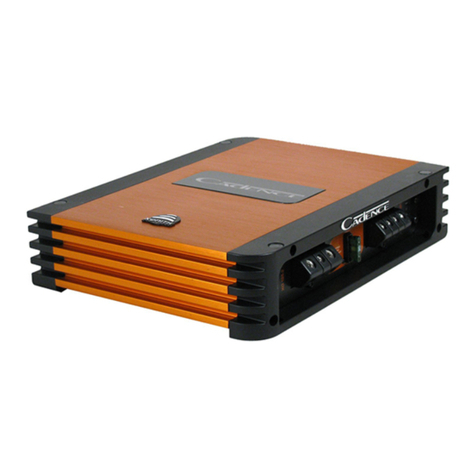
Cadence Q DRIVE SERIES User manual


ThankyouforpurchasingaCadenceQSeriesamplifier.Overthepastyears,thetechnologyusedtocreateaudioamplifiershasgrown
by leaps and bounds. We have tens of thousands of satisfied customers still using our first generation Ultra Drive amplifiers which are
more than 10 years old. Our competition is satisfied with just continuing to build the same units year after year without thought for
improvement,but notCadence. Weconsideritourmissiontouseourexpertiseindevelopingthelatesttechnologiesandtobringyou
theabsolutebestsounding,mostpowerfulamplifiersonthemarketandofcourseatareasonableprice.Weareveryproudtointroduce
this third generation of Q Series amplifiers featuring C-FORCE technology, "ARVA" and "ADR" circuitry. You will be amazed at the
qualityandpowerthatthesenewampsoffer.Youwill"Boom-Harder!"with QSeriesamplifiers.
Wehavesparednoexpenseindesigningtheseamplifiers,creatingthemostrugged,reliable,powerfulandbestperformingamplifiers.
In fact we are so sure of the quality we backup every Q Seriesamplifier with our exclusive two-year warranty which exemplifies our
commitmenttoexcellenceincaraudiomusicalreproduction.(Seeenclosedwarrantycardfordetails.)
Please read this installation guide carefully for proper use of your Cadence power amplifier. Should you need technical assistance
during or after your installation please call our technical-line between 9:30 am and 5:00 PM EST at 732/370-5400. Read this entire
guidefullybeforeattemptingyourinstallation.
Wheninstalling theamplifier, secureit tightly.An unmountedamplifier inyourcar cancause seriousinjuryto passengersand damage
toyourvehicleifitissetinmotionbyanabruptdrivingmaneuverorshortstop.
WARNING: BE AWARE! Use of this amplifier at extreme high volumes for extended periods of time may cause hearing loss and or
hearingdamage.During periodsofprolongedhigh volumelevels itisrecommendedthat youuse earsafetydevices.Playing Cadence
amplifiers at high volume levels while driving will impair your ability to hear necessary traffic sounds. While driving always keep your
soundvolumeatreasonablelevels.WeatCadencewantyoulisteningformanyyearstocome.
!

All the terminals on the amplifier are solid brass and gold plated for high conductivity and
minimum impedance loss. The power and ground terminals are extra large and capable of
accepting4-8gaugewire.The speakerterminals canaccept 16gauge wire.When wiringthe
amplifier, be sure to strip just enough wire that fits into the terminal so that bare wires do not
toucheachother,ortheamplifierchassisandcauseashortcircuit.
A narrow "Q" shelving equalization circuit is included in the amplifiers. The equalization
systemispresetat45Hz.Theboost controlallowsyoutoaddupto12dBof BassDriveeffect.
Utilize the Bass Drive to tailor your bass response to your systems needs. Please keep in
mind that by adding Bass Drive you are adding stress on your speakers. Make sure your
speakers can handle the extra power output! It would be foolish to add 12dB of gain to low
excursion8"and10"Subwoofers.
Cadence Q Series amplifiers feature our proprietaryADR, Active Dynamic Regulated power
supplies. 100% HexFET devices are utilized in the power supply for high speed (100KHz)
switchingfrequencies.The powersupplies arecapableof supplyingthe mainamplifier witha
considerable amount of reserve voltage for peak "high demand" situations. TheADR circuit
provides full bandwidth power for authoritative bass response, high current output into low
impedanceloadsandincreasedheadroom.TheADRissuppliedwithpowerviaahighspeed,
high temperature capacitance bank and 100% pure copper rails on the PCB enabling fast
transientresponsetomusicaldemands.
The audio output section of the Q Series amplifiers feature Japanese studio grade, high
currentBiPolaraudio transistors.Unlike othermanufacturers whouse ahost ofdifferenttype
transistors, not originally designed for audio output, ie: power supply transistors, motor
control transistors to produce the audio signal, (You can only imagine what they sound like.)
Cadenceuses only true audio transistors.These transistorswere designed and engineered
to produce music. That’s why Cadence amplifiers sound better. They are cleaner with lower
distortion, higher current capable and more reliable. We challenge you to test listen a
Cadenceamplifierandhearthedifferenceyourself.
Q Series amplifiers feature our unique IC controlled protection circuitry. This sophisticated
circuit constantly monitors the heatsink internal temperature and various voltages, adjusting
the amp automatically and protecting it from dangerous conditions. The 2 LEDs located on
the input side of the amplifier provide indication of the amplifier status, the Power LED will
light when the amplifier is receiving proper power, ground and remote voltages and the IC
monitoring sequence indicates the amp is functional. In case the amplifier encounters a
diagnostic condition as listed below, the second LED will light indicating a Diagnostic
condition. When a diagnostic condition is sensed the amplifier will then turn into a self
preservationmode andifthe causeof thediagnostic conditionis notcorrected willeventually
shut off. There are certain critical diagnostic conditions which will turn the amplifier off
immediately.
1. Speaker short circuit.
2. Input Overload.
3. Thermal overload.
4. Reverse Polarity.
To reset the amplifier, you mustfirst diagnose what causedthe problem, correct thefault and
restartthesystem.SeetheTroubleShootingpageforfurtherdetails.
The Q Series amplifiers feature an anti-thump, mute and delay circuit. This eliminates
irritating and speaker damaging turn-on and turn-off transients normally experienced with
lessexpensiveamplifiers.

Cadence Q Series amplifiers feature "ARVA" circuitry in their power supply. This circuit
constantly monitors the output stage and under high current demands will adjust the power
supply rail voltages so that enough power is available for peak situations. The "ARVA" also
improves the damping factor of the amplifier when playing low impedance mono loads.
Cadence Q Series amplifiers have tighter sounding bass reproduction thanks to this unique
circuitry.
CadenceQ Series amplifiers are rated and regulated to 13.8 volts and below. Increasing
voltage to 14.4 volts will increase the power output of the amplifier in the same proportion.
Maximuminputvoltageis14.4voltswhiletheminimumvoltageis12volts.
DONOTEXCEED14.4INPUTVOLTAGE.
CadenceQSeriesamplifiersarenotcompetitionstyleamplifiers!
Cadence amplifiers incorporate many outstanding protection circuits to help protect the
amplifierfrombeingdamagedduringoperatingconditions.
Ifyouliveinahotclimatewesuggestinstallingadditionalcoolingfansinyourtrunktoexhaust
the hot air which can build up in the trunk this will help keep the ambient temperature in the
trunk as low as possible so that your amps work flawlessly and without any musical
interruption.
Thermal Protection: When the amplifier reaches an unsafe operating temperature of 80
degrees Celsius the amplifier will turn off. Once the amplifier cools down, simply reset the
amplifier by its Remote connection, (turn the amplifier off and then on again once you have
giventheamplifierachancetocooldown)andtheampwillonceagainbegintoplay.
Speaker Short Circuit Protection: Shouldyour speakers shortcircuit dueto voice coilburn
out, or should the amplifier sense an impedance too low to handle, the Protection LED will
light,indicatingadiagnosticcondition.Turnoffyoursystem,disconnectonespeakeratatime
and try to determine which speaker might be faulty. Correct the condition and restart the
amplifier. You must reset the amplifier by turning off and then on by the Remote power for
properoperationaftercorrectingadiagnosticcondition.
Clippingortotal shutdownmayalso bearesult ofabad groundconnectionor looseground.If
you find that your speakers and speaker wires are not shorted, please check your ground
connection.
Input Overload Protection: This circuit will either shutdown the amplifier completely or
make the amplifier spurt on and off indicating that it is in a diagnostic condition. Turn the
system off and reduce the gain on the amplifier or volume from your head unit, this should
resultinacorrectedcondition.
DC Offset Protection: Should any DC voltage try to enter the amplifier via the speaker
terminals it will cause the amplifier to shut down and not operate until this condition is
remedied. This circuit will also protect damaging high DC voltages from reaching your
speakersshouldyouramplifierevermiss-function.
Beforeyou begin with yourinstallation disconnect the NEGATIVE(-) terminal fromyour car's
battery. This safety precaution will avoid possible short circuits while wiring your amplifier.
Cadenceamplifiersoperateon12-voltnegativegroundsystemsonly.
It is recommend that you layout your sound system design on paper first. This will help you
during the installation so that you will have a wiring flow chart and not miss-wire any of your
components.
Mount the amplifier in the trunk or hatch area of your vehicle. Never install an amplifier in the
engine compartment or on the firewall. Please be sure to leave breathing room around the
amplifierheatsink so thatit can dissipatethe heat itproduces efficiently.The amplifier canbe
installedeitherhorizontallyorvertically.
When mounting the amplifier on the trunk floor, be sure to watch for your gas tank, gas lines
andelectrical lines.Do notdrill ormount anyscrews wherethey mightpenetrate thegas tank
ofyourcar.

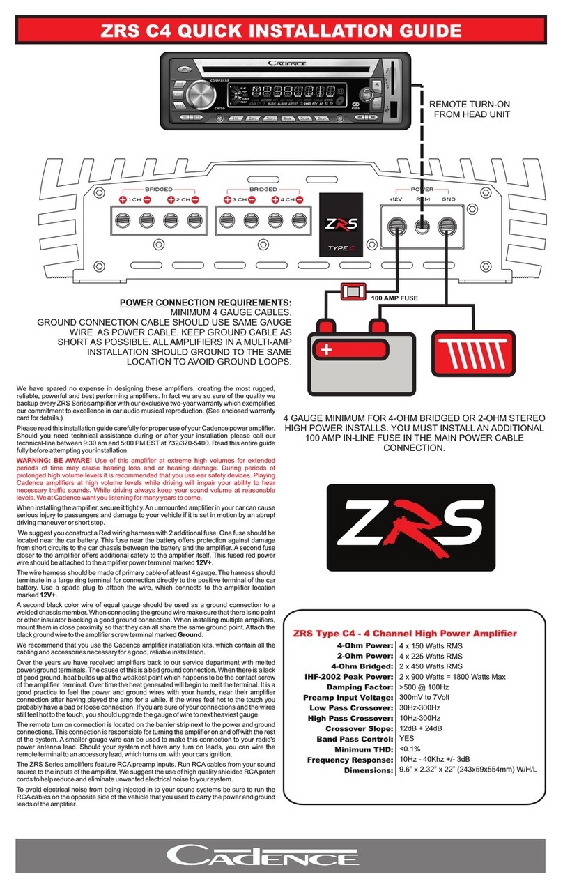
The remote turn on connection is located on the barrier strip next to the power and ground
connections.This connectionisresponsibleforturning theamplifieronandoff withtherestof
the system.A smaller gauge wire can be used to make this connection to your radio's power
antenna lead. Should your system not have any turn on leads, you can wire the remote
terminaltoanaccessorylead,whichturnson,withyourignition.
The Q Series amplifiers are supplied with built-in fuses, never replace the fuse that the amp
camewith,withoneofalargervalue.
We suggest you construct a Red wiring harness with 2 additional fuse. One fuse should be
locatednearthe carbattery.Thisfuse nearthebattery offersprotectionagainstdamage from
shortcircuitsto thecar chassisbetween thebattery andthe amplifier.Asecond fusecloser to
theamplifieroffersadditionalsafetytotheamplifieritself.Thisfusedredpowerwireshouldbe
attachedtotheamplifierpowerterminalmarked12V+.
The wire harness should be made of red primary cable of at least 4-8 gauge. The harness
should terminate in a large ring terminal for connection directly to the positive terminal of the
car battery. Use a spade plug to attach the wire, which connects to the amplifier location
marked12V+.
Asecondblackcolor wireof equalgaugeshould beused asa groundconnectionto awelded
chassis member. When connecting the ground wire make sure that there is no paint or other
insulatorblockingagoodgroundconnection.Wheninstallingmultipleamplifiers,mountthem
in close proximity so that they can all share the same ground point.Attach the black ground
wiretotheamplifierscrewterminalmarkedGround.
We recommend that you use the Cadence ZIK-8 or ZIK-4 amplifier installation kit, which
containsallthecablingandaccessoriesnecessaryforagood,reliableinstallation.
Over the years we have received many an amp back to our service department with melted
power/groundterminals.Thecauseofthisisabadgroundconnection.Whenthereisalackof
good ground heat builds up at the weakest point which is the contact screw of the terminal.
Over time the heat generated will begin to melt the terminal. It is a good practice to feel the
power and ground wires with your hands, near their amplifier connection after having played
the amp for a while. If the wires feel hot to the touch you probably have a bad or loose
connection. If you are sure of your connections and the wires still feel hot to the touch, you
shouldupgradethegaugeofthewiretonextheaviestgauge.
AUDIOPREAMPINPUT
USINGTHEBUILT-IN LOWPASSELECTRONICCROSSOVER
The Q Series amplifiers feature RCA preamp inputs. Run RCA cables from your sound
source to the inputs of the amplifier. We suggest the use of high quality shielded RCApatch
cordstohelpreduceandeliminateunwantedelectricalnoisefromyoursystem.
Be sure to run the RCAcables on the opposite side of the vehicle that you used to carry the
powerandgroundleadsoftheamplifier.
All the Q Series amplifiers feature 12dB per octave fully adjustable low-pass and high pass
electronic crossovers.
ForLow Pass systems, set the crossovermode switch to LOW PASS. Now theknob marked
FREQUENCY will control the low pass frequencies from 50Hz to 250Hz.Afrequent mistake
made is setting the low pass frequency too low, especially when using vented subwoofer
enclosures. We recommend that for most installations you do not set the frequency knob
lowerthan100Hz(the12o’clockposition).
Whenusing the amplifiersfor component speakers orcoaxials, you willwant to setthe mode
switch to HI PASS. The FREQUENCY control knob adjusts the high pass frequencies
between50Hzand250Hz.Donotattachtweetersdirectlytotheseamplifiers,eveninthehigh
pass mode without a secondary passive crossover to protect them. 250Hz high pass is not a
frequencyhighenoughfortweeters.
QSeriestwochannelcrossoversection,locatedunderthelightupplasticplate.
Oncethe systemis operational, thefirst thingto do,is set allcrossover pointsto approximate
settings.Inthe caseofthe basicsubwoofersystem LowPass filtercrossoverat 100Hzor so.
SettheBassBoost equalizercontrolsto0dB
Now you should set the amplifiers LEVEL adjustment.The knob accessible on the top of the
amplifiermarkedInputLeveladjuststheinputsensitivityfrom150mVto5Volts.
Toadjust theinputsensitivity, turnthecontrol usingasmall flathead screwdriverfullycounter
clock wise to the minimum position. Do not apply any pressure while turning as this might
breakthe control unit.Adjust yourradio volume level tomaximum volume. Nowturn the level
control on the amplifier clockwise towards the Maximum marking and until audible distortion
occurs. When you begin to hear any distortion in the sound, back down one notch and your
ampisset.Itishelpfultohaveasecondpersontohelpyousetthegain.
When setting up a multi-amp system, set each amplifier’s gain separately. Start off with the
bassamplifier,thenadjustthehighsamplifier’slevelcontroltomatch.
Once you are satisfied with the level control settings, use the equalizer controls to adjust the
system tonal level for personal preference. Keep in mind that after equalizing, you may have
togobackandresetthelevelcontrols.
The level control of any car amplifier should not be mistaken for a volume control. It is
a sophisticated device designed to match the output level of your source unit to the
input level of the amplifier. Do not adjust the amplifier gain to maximum unless your
inputlevelrequiresit.
Yoursystem canalsobeextremelysensitivetonoise whentheLEVELisset tomaximumand
doesnotmatchyourinputsignal. Thegainadjustmentsneedtobemadeonlyoncewhen first
settingupthesystem.
Ifyourunithasbeenprofessionallyinstalledpleasedonot changethegainsettingssetbythe
installer,heistheprofessional!
Channel 3/4Channel 3/4
USINGTHEELECTRONICCROSSOVER-4CHANNELMODEL
The four channel models feature separate crossovers for channels 1-2 and 3-4. All the Q
Series amplifiers feature 12dB per octave fully adjustable low-pass and high pass electronic
crossovers.
FOURCHANNELAMPLIFIERCONFIGURATIONS.
1.AllfourchannelsHighPassforinternalcomponentspeakersindoorsandreardecks.
2. Channels 1 and 2 High Pass for front component speakers, while channels 3 and 4 are
wiredtosubwoofers.
3.Bridgechannels1and2forsinglehigh powersubwooferchannel.Bridgechannels3and4
forsecondhighpowersubwooferchannel.
ForLow Pass systems, set the crossovermode switch to LOW PASS. Now theknob marked
FREQUENCY will control the low pass frequencies from 50Hz to 250Hz.Afrequent mistake
made is setting the low pass frequency too low, especially when using vented subwoofer
enclosures. We recommend that for most installations you do not set the frequency knob
lowerthan100Hz(the12o’clockposition).
When using the amplifiers for component speakers or coaxial, you will want to set the mode
switch to HI PASS. The FREQUENCY control knob adjusts the high pass frequencies
between50Hzand250Hz.Donotattachtweetersdirectlytotheseamplifiers,eveninthehigh
pass mode without a secondary passive crossover to protect them. 250Hz high pass is not a
frequencyhighenoughfortweeters.

Chooseaconvenientmountinglocationwithunobstructedairflow.
TheQamplifiersfeaturefourplasticmountingtabslocatedattheamplifiersfourcorners.Youwillneedtoremove
thelight-upacrylicpanelandthechrometrimplatetoaccessthesemountingtabs.
Usingthesuppliedscrews,gentlymounttheamplifierintoposition.Donotovertightenthescrews.
All Q series amplifiers come with three molded acrylic covers in
red, blue and orange. The cover is held down with four thumb
screws. The amplifier crossover and gain controls are located
under the cover. Please note that the length of the four thumb
screwsaredifferent,therearetwoshortones andtwolongones.
The shorter screws are for the lower shelf of the acrylic cover,
while the longer screws fit the raised shelf area of the acrylic
cover.
There is an area of multiple white neon LED bulbs underneath
the cover which transmit the light through the cover. By simply
changing the cover you can change your amplifier installation
colortoeitherblue,redororange.
Please take special care not to scratch the surface of the acrylic
covers. Clean them only with a soft damp towel. The use of any
cleansers may scratch the surface and remove the silver
stampingofthelogo.
Replacement covers and thumb screws are available from
Cadence.


Channel 3/4Channel 3/4

Channel 3/4Channel 3/4

Please note that the minimum impedance load for single
Cadence Q Series amplifiers is 2 ohm stereo and 4 ohm
mono bridged.
Lower impedance loads will cause overheating and may
damage the amplifiers.
Do not mix different type and different impedance
speakers in the series and/or parallel combinations, as
unequal power sharing and acoustic outputs will result.

12
Due to constant product improvements, these specifications
are subject to change without notice. High current rated
powers are at amplifier minimum distortion and are for
competition purposes. Not responsible for typographical
errors. Copyright by Cadence Sound Systems, Inc. 2003
4 Ohm Stereo Power:
2 Ohm Stereo Power:
4 Ohm Bridged Mono Power:
Dimensions (LxWxH):
Input level adjustment range:
Low pass filter adjustment range:
Low pass filter slope:
Bass boost range:
Bass boost center frequency adjustment range:
Signal to noise ratio:
Damping factor:
Minimum THD&N:
Frequency Response:
150 mV to 5 Volt
50 Hz to 250 Hz
12 dB/octave
0 dB to +12 dB
45 Hz
> 100 dB
>200 @ 100 Hz
<0.05%
20Hz - 35KHz
COMMON TO ALL MODELS
!
2 x 75 Watts
2 x 125 Watts
1 x 250 Watts
9” x 10.75” x 2.5”
2 x 125 Watts
2 x 175 Watts
1 x 350 Watts
12.75” x 10.75” x 2.5”
2 x 175 Watts
2 x 250 Watts
1 x 500 Watts
17.75” x 10.75” x 2.5”
4 x 75 Watts
4 x 125 Watts
2 x 250 Watts
13.75” x 10.75” x 2.5”
SPECIFICATIONS
This manual suits for next models
4
Table of contents
Other Cadence Amplifier manuals

Cadence
Cadence Q2000 User manual

Cadence
Cadence FXA 2500.1D User manual

Cadence
Cadence ZA12KW User manual

Cadence
Cadence Xenith User manual

Cadence
Cadence FXA Series User manual

Cadence
Cadence SQA1200.1 User manual

Cadence
Cadence QRS Series User manual

Cadence
Cadence MONO CLASS D User manual

Cadence
Cadence ZRS C4 User manual

Cadence
Cadence Q 300ID User manual
Popular Amplifier manuals by other brands

Power bass
Power bass XTA 4000D owner's manual

Power bass
Power bass XL-355DM owner's manual

Channel Plus
Channel Plus DA-8200BID user manual

Contro l4
Contro l4 AVM-16A1-B Installation and user guide

Aetechron
Aetechron 8500 Series Operator's manual

protech
protech INTEGRA III 800 Series Installation & operation manual