caenrfid Quattro R4321P Technical document

TECHNICAL INFORMATION MANUAL
Revision 3 –29 September 2020
R4321P
Smart 4-port RAIN RFID Long Range Reader

Visit the Quattro R4321P web page, you will find the latest revision
of data sheets, manuals, certifications, technical drawings, software and firmware.
All you need to start using your reader in a few clicks!
Scope of Manual
The goal of this manual is to provide the basic information to work with the Quattro R4321P Smart 4-port
RAIN RFID Long Range Reader.
This manual refers to Quattro R4321P DISTRO firmware revision 1.2.0.
Change Document Record
Date
Revision
Changes
Pages
16 Sep 2019
00
Preliminary Release
-
17 Feb 2020
01
Added CE Compliance paragraph and Quattro R4321P CE
Declaration of Conformity
67, 69
Added notes regarding the Ethernet cable specification
9, 17, 41
06 Apr 2020
02
Added FCC Compliance paragraph and Quattro R4321P FCC
Grant
68, 70
29 Sep 2020
03
Added Installation Notice paragraph
7
Modified RFID paragraph
21
Modified EASY2READ Configuration Options and CUSTOM
Configuration Options paragraphs
22, 34
Added HID Profile chapter
49÷53
Added HID Configuration Options paragraph
25
Modified EASY2READ Profile and CUSTOM Profile chapters
37÷40, 54÷57
Added firmware revision in Scope of Manual paragraph
2
Added Connecting to RA0003 Multiplexer chapter
65÷67
Reference Document
[RD1] EPCglobal: EPC Radio-Frequency Identity Protocols Class-1 Generation-2 UHF RFID Protocol for
Communications at 860 MHz –960 MHz, Version 2.0.1 (April, 2015).
[RD2] G.S.D. s.r.l. - Report CE mark –R4321P –Quattro. Test report n. 19517 Rev. 00 –03 January 2020.
[RD3] CMC Centro Misure Compatibilità S.r.l. - Report Federal Communication Commission (FCC) –
Quattro R4321P –Smart 4-port RAIN RFID Long Range Reader. Test report n. R20020701 Rev.
1.0 –05 Mar 2020
[RD4] CMC Centro Misure Compatibilità S.r.l. - Report Federal Communication Commission (FCC) –
Quattro R4321P –Smart 4-port RAIN RFID Long Range Reader. Test report n. R20020801 Rev.
1.0 –05 Mar 2020
CAEN RFID srl
Via Vetraia, 11 55049 Viareggio (LU) - ITALY
Tel. +39.0584.388.398 Fax +39.0584.388.959
info@caenrfid.com
www.caenrfid.com

© CAEN RFID srl –2020
Disclaimer
No part of this manual may be reproduced in any form or by any means, electronic, mechanical, recording,
or otherwise, without the prior written permission of CAEN RFID.
The information contained herein has been carefully checked and is believed to be accurate; however, no
responsibility is assumed for inaccuracies. CAEN RFID reserves the right to modify its products
specifications without giving any notice; for up to date information please visit www.caenrfid.com.
Federal Communications Commission (FCC) Notice
This device was tested and found to comply with the limits set forth in Part 15 of the FCC Rules. Operation
is subject to the following conditions: (1) this device may not cause harmful interference, and (2) this device
must accept any interference received including interference that may cause undesired operation. These
limits are designed to provide reasonable protection against harmful interference when the equipment is
operated in a commercial environment.
This device generates, uses, and can radiate radio frequency energy. If not installed and used in accordance
with the instruction manual, the product may cause harmful interference to radio communications.
Operation of this product in a residential area is likely to cause harmful interference, in which case, the user
is required to correct the interference at their own expense. The authority to operate this product is
conditioned by the requirements that no modifications be made to the equipment unless the changes or
modifications are expressly approved by CAEN RFID.
Disposal of the product
Do not dispose the product in municipal or household waste. Please check your local regulations for
disposal/recycle of electronic products.

Index - Quattro Technical Information Manual 4
Index
Scope of Manual.........................................................................................................................................................2
Change Document Record .........................................................................................................................................2
Reference Document .................................................................................................................................................2
Index ....................................................................................................................................................................................4
List of Figures .....................................................................................................................................................................5
List of Tables.......................................................................................................................................................................5
1INTRODUCTION ........................................................................................................................................................6
Product Description ...................................................................................................................................................6
Ordering Options .......................................................................................................................................................6
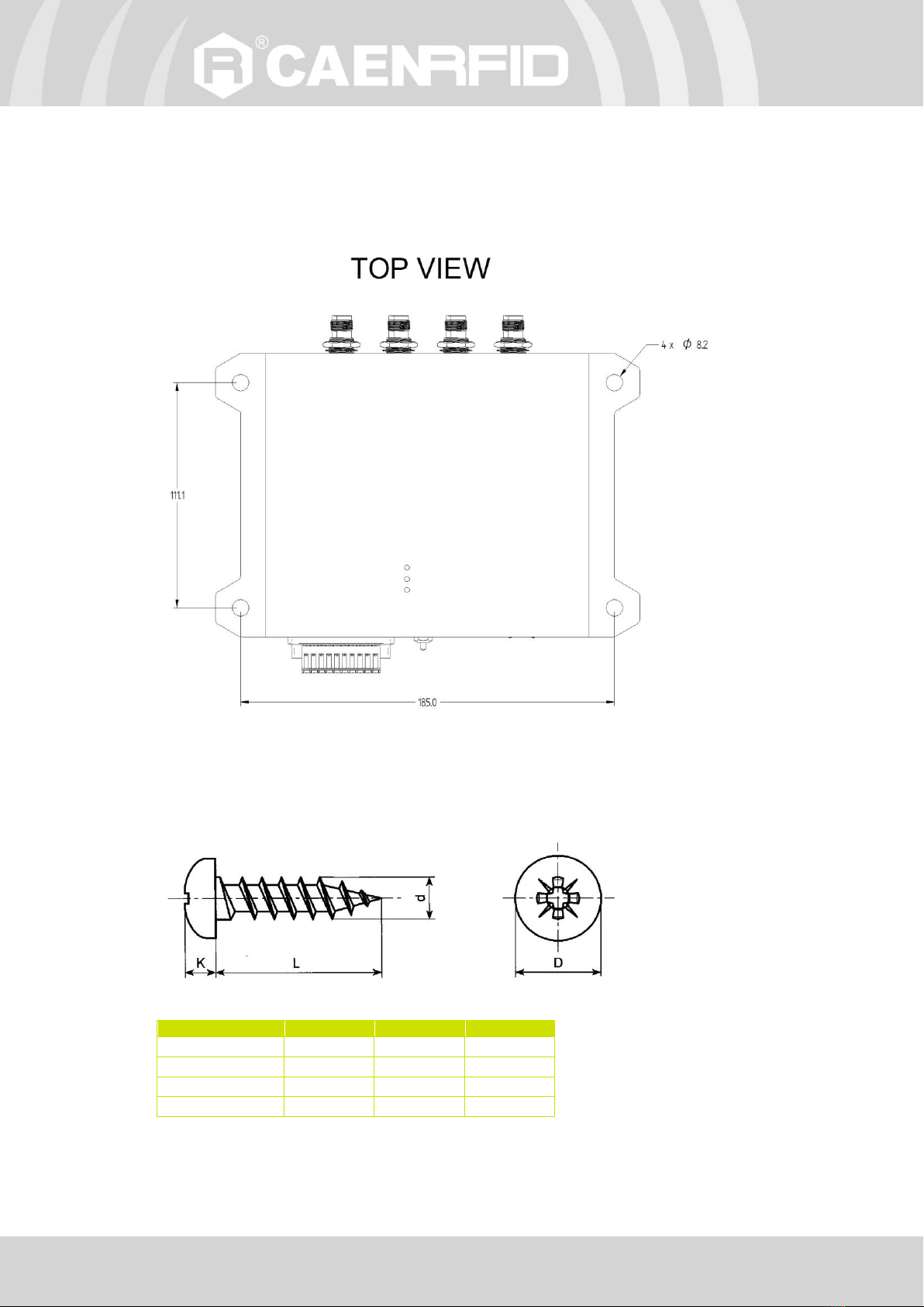
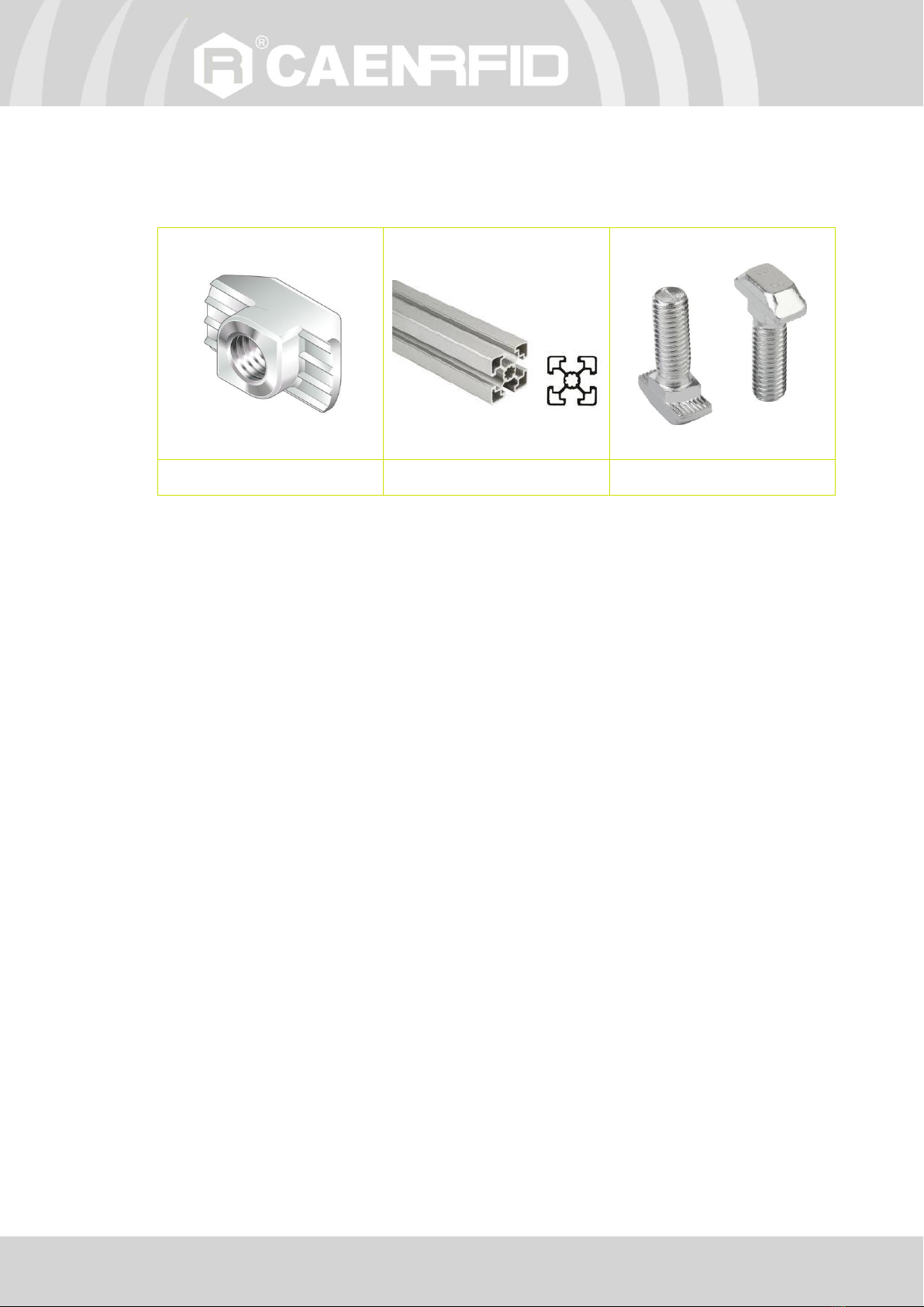
Installation Notice ......................................................................................................................................................7
2GETTING STARTED ...................................................................................................................................................9
Introduction................................................................................................................................................................9
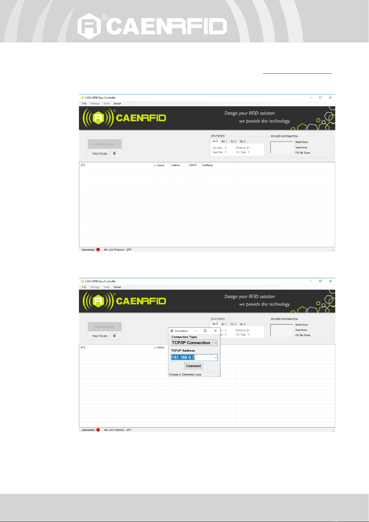
Connecting to the Quattro Reader using the Ethernet port.....................................................................................9
Ethernet Communication Setup .....................................................................................................................9
Easy Controller ............................................................................................................................................. 10
3EXTERNAL INTERFACE DESCRIPTION.................................................................................................................. 12
LEDS.......................................................................................................................................................................... 12
Connectors............................................................................................................................................................... 13
GPIO.............................................................................................................................................................. 13
Antennas .................................................................................................................................................................. 16
4CONFIGURATION USING THE WEB INTERFACE................................................................................................... 17
Introduction.............................................................................................................................................................. 17
NETWORK................................................................................................................................................................. 19
SYSTEM..................................................................................................................................................................... 20
RFID .......................................................................................................................................................................... 21
EASY2READ Configuration Options ............................................................................................................. 22
HID Configuration Options ........................................................................................................................... 25
EPC code parameters............................................................................................................................. 30
EXAMPLES.............................................................................................................................................. 33
CUSTOM Configuration Options .................................................................................................................. 34
INFO.......................................................................................................................................................................... 36
5EASY2READ PROFILE ............................................................................................................................................. 37
Introduction.............................................................................................................................................................. 37
Set the EASY2READ profile...................................................................................................................................... 37
EASY2READ configuration options .......................................................................................................................... 40
Connecting using the Ethernet port ........................................................................................................................ 41
Ethernet Communication Setup ................................................................................................................... 41
Easy Controller ............................................................................................................................................. 42
Connecting using the USB port................................................................................................................................ 44
USB Communication Setup........................................................................................................................... 44
Easy Controller ............................................................................................................................................. 45
Inventory on GPIO state change .............................................................................................................................. 47
6HID PROFILE............................................................................................................................................................ 49
Introduction.............................................................................................................................................................. 49
Set the HID profile.................................................................................................................................................... 49
HID configuration options........................................................................................................................................ 52
Connecting using the Ethernet port ........................................................................................................................ 53
Ethernet Communication Setup ................................................................................................................... 53
Connecting using the USB port................................................................................................................................ 53
USB Communication Setup........................................................................................................................... 53
7CUSTOM PROFILE................................................................................................................................................... 54
Introduction.............................................................................................................................................................. 54
Set the CUSTOM profile ........................................................................................................................................... 54
Configuration options .............................................................................................................................................. 57
Connecting using the Ethernet port ........................................................................................................................ 58
Ethernet Communication Setup ................................................................................................................... 58
Java Virtual Machine ................................................................................................................................................ 58
8RESET THE READER................................................................................................................................................ 60
9FIRMWARE UPGRADE ............................................................................................................................................ 61
10 TECHNICAL SPECIFICATIONS................................................................................................................................ 64
Technical Specification Table ................................................................................................................................... 64

Index - Quattro Technical Information Manual 5
11 CONNECTING TO RA0003 MULTIPLEXER............................................................................................................. 65
RA0003 Multiplexer ................................................................................................................................................. 65
Quattro R4321P –RA0003 Multiplexer Connection ................................................................................................ 66
12 REGULATORY COMPLIANCE ................................................................................................................................. 67
CE Compliance.......................................................................................................................................................... 67
FCC Compliance........................................................................................................................................................ 68
RoHS EU Directive .................................................................................................................................................... 68
Quattro R4321P CE Declaration of Conformity ....................................................................................................... 69
Quattro R4321P FCC Grant ...................................................................................................................................... 70
List of Figures
Fig. 1.1: Quattro reader (Model R4321P) .............................................................................................................................6
Fig. 1.2: Quattro R4321P Technical drawings: top view.......................................................................................................7
Fig. 3.1: LEDs....................................................................................................................................................................... 12
Fig. 3.2: Interfaces Panel .................................................................................................................................................... 13
Fig. 3.3: GPIO Connector .................................................................................................................................................... 13
Fig. 3.4: GPIO Input Signal .................................................................................................................................................. 14
Fig. 3.5: GPIO Output Signal............................................................................................................................................... 16
Fig. 3.6: Antennas ............................................................................................................................................................... 16
Fig. 4.1: Quattro R4321P Web Interface ............................................................................................................................ 18
Fig. 5.1: Quattro R4321P Web Interface ............................................................................................................................ 38
Fig. 6.1: Quattro R4321P Web Interface ............................................................................................................................ 50
Fig. 7.1: Quattro R4321P Web Interface ............................................................................................................................ 55
Fig. 11.1: RA0003 UHF Antenna Multiplexer...................................................................................................................... 65
Fig. 11.2: Quattro reader –RA0003 MUX Connection ....................................................................................................... 66
List of Tables
Tab. 1.1: Cylindrical-head self-tapping screw measures ......................................................................................................7
Tab. 3.1: LEDs ..................................................................................................................................................................... 12
Tab. 3.2: Interfaces Panel ................................................................................................................................................... 13
Tab. 3.3: GPIO Connector Poles ......................................................................................................................................... 14
Tab. 3.4: Antennas .............................................................................................................................................................. 16
Tab. 4.1: Conducted power ................................................................................................................................................ 23
Tab. 4.2: Conducted power ................................................................................................................................................ 26
Tab. 4.3: EPC Code parameters .......................................................................................................................................... 30
Tab. 4.4: Escape Sequences supported .............................................................................................................................. 31
Tab. 4.5: Conducted power ................................................................................................................................................ 35
Tab. 10.1: Technical Specifications..................................................................................................................................... 64

INTRODUCTION - Quattro Technical Information Manual 6
1INTRODUCTION
Product Description
The Quattro (Model R4321P) is a smart 4-port RAIN RFID long range reader of the easy2read©product line,
well suited for retail and warehousing installations.
The Quattro reader has 4 antenna ports capable of a 31.5 dBm maximum power enabling to build RAIN
RFID portals for long range reading. Its slim form factor makes it easy to install even when limited space is
available. It offers the Ethernet (PoE) and USB communication interface in order to simplify the installation
both on large and single read point installations. The Power over Ethernet capability permits to provide
power and to communicate with the reader with a single cable.
The USB host port, combined with the internal computing architecture, permits to connect USB peripherals
like barcode scanners, keyboards, printers and many others transforming the Quattro reader in a powerful
and versatile identification platform.
The Quattro is based upon an embedded Linux platform and it’s easily configurable using an internal web
interface. System integrators can customize the behaviour of the reader installing Java code that, having
access to all the RFID features and interfaces, permits a full customization.
The Quattro reader complies with and can operate in both European and US regulatory environments and,
due to its multiregional capabilities, it’s ideal for integration in devices requiring compliance to different
geographical regions.
Fig. 1.1: Quattro reader (Model R4321P)
Ordering Options
Code
Description
Reader
WR4321PXAAAA
R4321P Quattro - Smart 4-port Long Range RAIN RFID
Development
kit
WR4321PXDKEU
Quattro - ETSI Dev Kit including RFID antenna with cable,
power supply, and tag samples (reader not included)
WR4321PXDKUS
Quattro - FCC Dev Kit including RFID antenna with cable,
power supply, and tag samples (reader not included)
Accessories
WANTENNAX019
Circular polarized antenna 8.5dBc –ETSI
WANTENNAX020
Circular polarized antenna 8.5dBc –FCC
WALIM0000005
R4321P - Auxiliary Power Supply

INTRODUCTION - Quattro Technical Information Manual 7
Installation Notice
The Quattro R4321P reader could be mounted either horizontally or vertically. Locate the four mounting
slots on the reader, as illustrated in Fig. 1.2: Quattro R4321P Technical drawings: top view. In the four
mounting slots there are rubber gaskets to facilitate adherence to smooth surfaces.
All measurements are in millimetres.
Fig. 1.2: Quattro R4321P Technical drawings: top view
Wall fixing
A cylindrical-head self-tapping screw (not provided) with the following measures is recommended to fix the
reader directly to the wall:
where:
Parameter
Min value
Max value
Unit
K
2
5
mm
L
50
100
mm
d
5
8
mm
D
9
15
mm
Tab. 1.1: Cylindrical-head self-tapping screw measures

INTRODUCTION - Quattro Technical Information Manual 8
Fixing on Bosch Rexroth’s profile
One of the fastenings that are very requested in the industrial field is the possibility of mounting on Bosch
profiles. The 4 fixing slots of the Quattro R4321P reader are sized to facilitate this type of assembly.
An M8 screw with the respective M8 nut is required to fix the reader using Bosch profiles:
M8 nut
Bosch Rexroth’s profile
M8 screw
Note that these accessories are not provided with the reader.

GETTING STARTED - Quattro Technical Information Manual 9
2GETTING STARTED
Introduction
This quickstart guide will help you to get started with your Quattro (Model R4321P) reader.
The reader can be configured in three different profiles:
EASY2READ (factory default): choosing this option you select the CAEN RFID easy2read
communication protocol. Select this option in order to control the reader using the CAEN RFID
Easy Controller Application or the SDK (Software Development Kits) library. For details on the
use of the EASY2RD profile please refer to this quickstart guide.
HID: choosing this option you select the keyboard emulation protocol.
For details on the use of the HID profile please refer to § HID PROFILE chapter page 49.
CUSTOM: the use of this profile allows the user to upload their own scripts to the reader. For
details on the use of the CUSTOM profile please refer to § CUSTOM PROFILE chapter page 54.
The reader is sold with the factory profile set to EASY2READ. This guide helps you to getting started with
your reader using the EASY2READ profile.
For more detailed information on reader configuration, connections and setup options please refer to the
next chapters.
Connecting to the Quattro Reader using the Ethernet
port
Ethernet Communication Setup
The Quattro reader can be connected to a PC using an Ethernet cable. In order to correctly operate with
the reader follow the steps above:
1. Connect the antenna cable to Ant-0 (see § Fig. 3.6: Antennas page 16) of the reader.
2. Connect the Quattro to the power supply, the power LED will turn on, wait about 30 seconds until
you hear a beep, wait 10 seconds again and the reader is ready to work with the EASY2READ profile
active.
3. Plug an Ethernet cable1(not provided) into your computer and connect the other end of the
Ethernet cable to the reader. If your private network matches the default network configuration of
the reader (IP address 192.168.0.2) you can connect to it, otherwise you can:
a. change the network configuration of the reader (see § NETWORK page 19) to connect it to
your network
or
b. disconnect your PC from your network and connect it to the network of the reader.
Now you can use the CAEN RFID Easy Controller Application to control the reader.
1For proper operation of the device:
-Ethernet cable shall be CAT6 at least (type S/FTP or S/STP)
-Put two ferrites (P.N. RRC-13-7-23-M-K5B by RICHCO; CAEN RFID ordering code LFAAFFP00004) on the Ethernet cable,
near the reader connector.

GETTING STARTED - Quattro Technical Information Manual 10
Easy Controller
Follow these steps to connect the Quattro reader using the Easy Controller application for Windows:
1. Download the latest version of the Easy Controller software from the Quattro R4321P web page,
Downloads section and install it.
2. Launch the Easy Controller application:
3. On the main screen click on File →Connect. A Connection windows will open. Select the Connection
Type (TCP/IP Connection) and type the Quattro IP address into the TCP/IP Address box (default value
is 192.168.0.2). Then click on Connect:

GETTING STARTED - Quattro Technical Information Manual 11
4. To verify if the connection with the reader has been established, check the green dot on the bottom
left side of the sidebar. Into the READER INFORMATION box you can find information on reader
model, serial number and firmware release:
5. Place a tag in the read range of the reader, click on start inventory and see the tag information
displayed on the main window:
For more info on the use of the Easy Controller, please refer to the CAEN RFID Easy Controller Software
Technical Information Manual, you can download it from the Quattro R4321P web page, Downloads section
or in the Manual and Documents web area.

EXTERNAL INTERFACE DESCRIPTION - Quattro Technical Information Manual 13
Connectors
Fig. 3.2: Interfaces Panel
No.
Name
Description
1
GPIO
General Purpose Input Output
2
UPGRADE
Upgrade operative system
3
USB host
USB 2.0 Hi-speed Host port
4
Power
Power Supply Connector
5
Ethernet
Ethernet 10/100/1000BASE-T (RJ45) / POE standard IEEE 802.3af
6
USB device
USB 2.0 Hi-Speed Device port
Tab. 3.2: Interfaces Panel
GPIO
10 Poles terminal block with screw connection with tension sleeve:
Fig. 3.3: GPIO Connector

EXTERNAL INTERFACE DESCRIPTION - Quattro Technical Information Manual 14
No.
Name
Description
1
+5V
5VDC
2
GND
Ground
3
GPI0
General purpose input 0
4
RTN
Return
5
GPI1
General purpose input 1
6
RTN
Return
7
OUTPUT1.1
SS-Relay 1 Contact 1
8
OUTPUT1.2
SS-Relay 1 Contact 2
9
OUTPUT2.1
SS-Relay 2 Contact 1
10
OUTPUT2.2
SS-Relay 2 Contact 2
Tab. 3.3: GPIO Connector Poles
Input signal
To have a valid input signal, apply a voltage between 4V and 48V to the pin indicated by GPI0 (or GPI1) and
its return (RTN) pin.
The most simply way to have a valid input signal is connecting the +5V pin, present on the terminal block
connector, to the GPI0 pin through a switch that enables the input signal when it is closed. The connection
between ground (GND) and return (RTN) is also required to complete the circuit.
Fig. 3.4: GPIO Input Signal
It is possible to verify the correct functioning of the circuit by connecting the reader to the CAEN RFID Easy
Controller software, Tools-I/O management section:
GPI0 corresponds to GPIO0 of the Easy Controller software
GPI1 corresponds to GPIO1 of the Easy Controller software

EXTERNAL INTERFACE DESCRIPTION - Quattro Technical Information Manual 15
When a valid input is present on the GPI0 pin, a check “۷”appears in the Status box at the GPIO 0:
Output signal
The OUTPUT1.1 –OUTPUT1.2 and OUTPUT2.1 –OUTPUT2.2 pins are the terminals of a normally open dry
contacts.
By connecting to the CAEN RFID Easy Controller Software, Tools-I/O management section, you can close
the contact by removing the check from the Status box related to GPIO 2 and GPIO 3 and then press the
Apply button.
OUTPUT1.1 –OUTPUT1.2 correspond to GPIO2 of the Easy Controller software
OUTPUT2.1 –OUTPUT2.2 correspond to GPIO3 of the Easy Controller software

EXTERNAL INTERFACE DESCRIPTION - Quattro Technical Information Manual 16
To power a generic device at 5V DC (U1 symbol in Fig. 3.5: GPIO Output Signal), for example a light signal
tower, a photocell or an alert siren, it is possible to use the connection shown in the drawing below. When
you close the contact by the software command, the device is powered.
Fig. 3.5: GPIO Output Signal
Antennas
Fig. 3.6: Antennas
Name
Description
ANT 0
50Ω RP-TNC jack connector Antenna 0
ANT 1
50Ω RP-TNC jack connector Antenna 1
ANT 2
50Ω RP-TNC jack connector Antenna 2
ANT 3
50Ω RP-TNC jack connector Antenna 3
Tab. 3.4: Antennas
In order to achieve the best reading performances, the VSWR of the antenna shall be lower than 1.5:1.

CONFIGURATION USING THE WEB INTERFACE -Quattro Technical Information Manual 17
4CONFIGURATION USING THE WEB
INTERFACE
Introduction
The reader can be configured via web interface.
The Web Interface is accessible only via the Ethernet connection:
1. Connect the Quattro reader to the power supply.
2. Plug an Ethernet cable2(not provided) into your computer and connect the other end of the
Ethernet cable to the reader. If your private network matches the default network configuration of
the reader (IP address 192.168.0.2) you can connect to it, otherwise you can:
a. change the network configuration of the reader (see § NETWORK page 19) to connect it to your
network
or
b. disconnect your PC from your network and connect it to the network of the reader.
By factory default, the Quattro web interface is reachable at the following IP address: 192.168.0.2.
To login, type root in the Username text box and root in the Password textbox. To change the username
and password please refer to § SYSTEM page 20.
2For proper operation of the device:
-Ethernet cable shall be CAT6 at least (type S/FTP or S/STP)
-Put two ferrites (P.N. RRC-13-7-23-M-K5B by RICHCO; CAEN RFID ordering code LFAAFFP00004) on the Ethernet cable,
near the reader connector.

CONFIGURATION USING THE WEB INTERFACE -Quattro Technical Information Manual 19
NETWORK
The NETWORK submenu options are the following:
DHCP: Enable/Disable. By default the DHCP is set to disable. You can change the default value
using the drop-down menu
IP Address: the reader default IP address is 192.168.0.2. The Quattro reader can be connected to
a PC using an Ethernet cable: in order to correctly operate with the reader refer to Ethernet
Communication Setup page 41.
Subnet Mask: the reader default subnet mask is 255.255.255.0.
Gateway: the reader default gateway is 192.168.0.1.
DNS Server: the reader default DNS server is 8.8.8.8.
Warning: To save the changes click on the “SAVE” button. Note that all changes made via the
web interface are active only after the reader’s reboot. Click on SYSTEM option in the Web
Interface panel and then click on the “Reboot” button. After reboot, the new settings are active.

CONFIGURATION USING THE WEB INTERFACE -Quattro Technical Information Manual 20
SYSTEM
The SYSTEM CONFIGURATION options are the following:
Login User Name: To access the web interface, the default username is “root”. Use this option to
change the login username.
If you forgot your username you must necessarily make a factory reset (see §
FIRMWARE UPGRADE page 61)
Login Password: To access the web interface, the default password is “root”. Use this option to
change the login password.
If you forgot your password you must necessarily make a factory reset (see §
FIRMWARE UPGRADE page 61)
Power Up Beep: enable or disable. By default, the Power Up Beep is enabled. Through this option
you can enable or disable the beep at the power up of the reader.
Package Upload: use this function to upload the script program to be used with the CUSTOM
profile. Give the package the same name used for the code. Please remember to keep your code
as simple as possible; the R4321P reader scripting capability is meant for running inside the
reader very simple task (max 3 MB). For more information on the use of the CUSTOM profile
please refer to § CUSTOM Profile page 54.
Warning: To save the changes click on the “SAVE” button. Note that all changes made via the
web interface are active only after the reader’s reboot. Click on the “Reboot” button. After
reboot, the new settings are active.
Table of contents
Other caenrfid Barcode Reader manuals