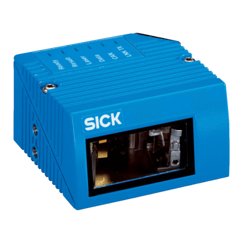
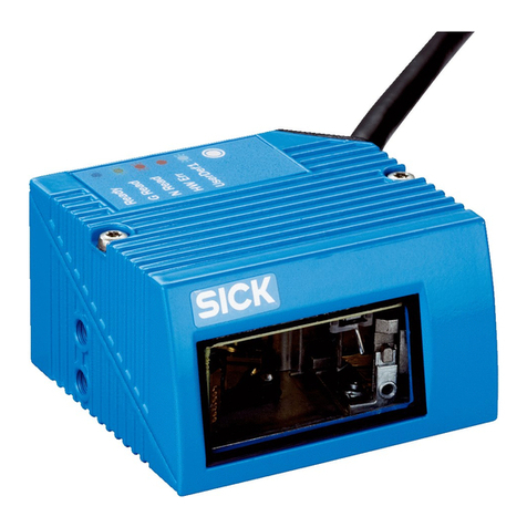
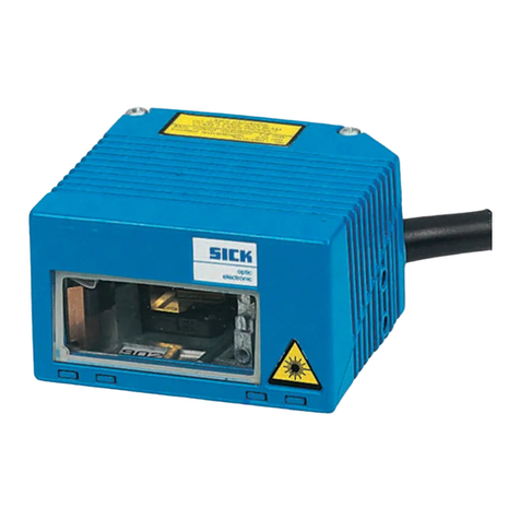
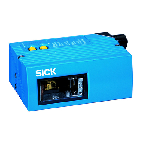
SICK CLP 100 User manual

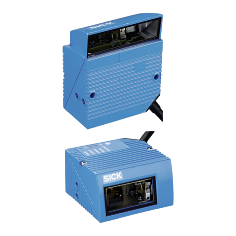
CLP 100
Bar Code Reader
O
PERATING
I
NSTRUCTIONS

Operating Instructions
CLP 100 Bar Code Reader
2© SICK AG · Division Auto Ident · German · All rights reserved 8 008 912/0000/21-08-2002
Described software state
Abbreviations used
CLP Code Leser Parallel (Code Reader Parallel)
CCD Charge Coupled Device
PLC Progammable Logic Controller
HTML H per Text Markup Language
LED Light Emitting Diode
Production state of the CLP 100
Windows 95™, Windows 98™, Windows NT™ and Internet Explorer™ are registered
trademarks or trademarks of the Microsoft Corporation in the USA and other countries.
I-ViewPro™ is a registered trademark of the EnReach Technolog , Inc., USA.
Software/Too Function Revision index
CLP 100 Firmware From V 1.10
CLP Setup User interface (window-based) From V 1.10
CLP Setup Help On-line help (HTML) From V 1.10
I-ViewPro™Off-line browser (HTML) V 2.38
Device type Revision index
CLP 100-0010 0000
CLP 100-2010 0000
CLP 100-0110 0000
CLP 100-2110 0000

Operating Instructions
CLP 100 Bar Code Reader
Contents
8 008 912/0000/21-08-2002 © SICK AG · Division Auto Ident · German · All rights reserved 3
Contents
1 Notes on this document...................................................................................................... 5
1.1 Function ................................................................................................................................... 5
1.2 Target audience.................................................................................................................... 5
1.3 Information content ............................................................................................................. 5
1.4 S mbols used........................................................................................................................ 5
2 Safety information................................................................................................................. 5
2.1 Authorized users................................................................................................................... 5
2.2 Intended use.......................................................................................................................... 6
2.3 General safet instructions............................................................................................... 6
2.4 Quick- Stop and Quick-Restart ........................................................................................ 6
2.5 Environmental information................................................................................................ 7
3 Product description .............................................................................................................. 7
3.1 Design....................................................................................................................................... 7
3.2 Working method of the device........................................................................................ 9
3.3 Displa and operating elements..................................................................................... 9
4 Insta ation.............................................................................................................................10
4.1 Installation sequence....................................................................................................... 10
4.2 Preparations for installation........................................................................................... 10
4.3 Installation and adjustment of the device................................................................ 13
4.4 Installing the reading-pulse sensor............................................................................. 14
4.5 Disassembling the device.............................................................................................. 15
5 E ectrica insta ation .........................................................................................................15
5.1 Electrical connections...................................................................................................... 15
5.2 Pin assignment of the connection plug or wire colors of the cable end...... 15
5.3 Planning the electrical installation ............................................................................... 16
5.4 Carr out the electrical installation.............................................................................. 16
6 Operation ...............................................................................................................................19
6.1 Startup steps ...................................................................................................................... 19
6.2 Default setting .................................................................................................................... 19
6.3 Quick-Start ........................................................................................................................... 20
6.4 Operating modes and output of the read result ................................................... 21
6.5 Parameterization................................................................................................................ 21
6.6 Switching off the CLP 100 ............................................................................................. 26
7 Maintenance.........................................................................................................................26
7.1 Maintenance during operation ..................................................................................... 26
7.2 Maintenance ....................................................................................................................... 27
7.3 Disposal ................................................................................................................................ 27
8 Troub eshooting...................................................................................................................28
8.1 Possible errors and faults .............................................................................................. 28
8.2 Troubleshooting table...................................................................................................... 29
8.3 SICK support....................................................................................................................... 30
9 Technica data......................................................................................................................31
9.1 Data sheet CLP 100 ........................................................................................................ 31
9.2 Dimensional drawings...................................................................................................... 32
10 Appendix ................................................................................................................................33
10.1 Appendix overview............................................................................................................ 33
10.2 Installation and handling of the CLP Setup software........................................... 33
10.3 Reading area diagram ..................................................................................................... 38
10.4 Calculation of the number of scans ........................................................................... 39
10.5 Calculation of the code length of a bar code ......................................................... 40
10.6 Command language for CLP bar code readers..................................................... 41

Operating Instructions
CLP 100 Bar Code Reader
4© SICK AG · Division Auto Ident · German · All rights reserved 8 008 912/0000/21-08-2002
Tab es and figures
Tab es
Tab. 3-1: Variants of the CLP 100......................................................................................................7
Tab. 3-2: Meaning of the LEDs .........................................................................................................10
Tab. 4-1: Permissible angle occurring between the scan line and the bar code bars 12
Tab. 5-1: Pin assignment of the connection plug ......................................................................15
Tab. 5-2: Assignment of the wire colors of the cable end......................................................16
Tab. 5-3: Maximum cables lengths between the CLP 100 and the host.........................16
Tab. 5-4: Communication parameters of the host interface (default setting) ................17
Tab. 5-5: Characteristic data of the "Sensor" switching input ..............................................18
Tab. 5-6: Characteristic data of the "Result" switching output.............................................19
Tab. 6-1: Default setting of the parameters of the CLP 100 ................................................20
Tab. 8-1: Troubleshooting table........................................................................................................29
Tab. 9-1: Technical specification of the CLP 100......................................................................31
Tab. 10-1: Default settings of CLP Setup ........................................................................................34
Tab. 10-2: Auxiliar table for calculating the code length of a bar code..............................40
Tab. 10-3: Command language for CLP bar code readers.......................................................41
Figures
Fig. 3-1: Design of the CLP 100 with face-end light emission ...............................................8
Fig. 3-2: Design of the CLP 100 with side light emission.........................................................8
Fig. 3-3: Function of the CLP 100 .....................................................................................................9
Fig. 4-1: Position of the threaded holes !at CLP 100 .........................................................11
Fig. 4-2: Reading distance to the object......................................................................................11
Fig. 4-3: 90 angle between the scan line and the bar code bars....................................12
Fig. 4-4: Reading angle occurring between the scan line and the bar code bars.......12
Fig. 4-5: Angle between the emitted light and the bar code
(tilted to the perpendicular).............................................................................................13
Fig. 4-6: Adjustment of the CLP 100 in order to avoid reflections;
a: With front-end light emission, b: With side-end light emission .....................13
Fig. 4-7: Installation site for the reading-pulse sensor and the reflector
(b smaller than a)................................................................................................................14
Fig. 5-1: Wiring the host interface ..................................................................................................17
Fig. 5-2: Wiring the terminal interface...........................................................................................18
Fig. 5-3: Wiring of the "Sensor" switching input........................................................................18
Fig. 5-4: Wiring of the "Result" switching output (NPN) .........................................................19
Fig. 6-1: Bar code sample (code 39, 0.35 mm, printing ratio 2:1)...................................21
Fig. 6-2: Terminal emulator with input of a command string ...............................................23
Fig. 6-3: Terminal emulator with reading results of the CLP 100
in diagnosis mode...............................................................................................................25
Fig. 7-1: CLP 100 with front-end reading window (a) and
side-end reading window (b) ..........................................................................................26
Fig. 9-1: Dimensions of the CLP 100 with front-end light emission in mm....................32
Fig. 9-2: Dimensions of the CLP 100 with side-end light emission in mm.....................32
Fig. 10-1: User interface of the CLP Setup software .................................................................36
Fig. 10-2: Reading area diagram.......................................................................................................38
Fig. 10-3: Calculation example: Number of scans for ladder positioning
of the bar code bars ..........................................................................................................39
Fig. 10-4: Calculation example: Number of scans for fencing positioning
of the bar code bars ..........................................................................................................39

Operating Instructions Chapter 1
CLP 100 Bar Code Reader
Notes on this document
8 008 912/0000/21-08-2002 © SICK AG · Division Auto Ident · German · All rights reserved 5
1Notes on this document
1.1 Function
This document instructs ou on using the CCD bar code reader CLP 100.
It contains information on
•Device installation and electrical installation
•Startup
•Operation and configuration (parameterization)
•Maintenance
1.2 Target audience
The target audience for this document consists of electricians, service technicians and
engineers.
1.3 Information content
This document contains all the information required for the installation, electrical installation
and startup of the bar code reader CLP 100 with the defau t setting in our works.
All actions are described step-b -step.
Parameterization of the CLP 100 for the app ication-specific reading configuration is
carried out with the CLP Setup user interface. Installation and use of the software are
described in the appendix.
Further information on the construction of the bar code reader as well as the bar code
technolog can be obtained from SICK AG, Auto Ident Division.
1.4 Symbo s used
Some information in this document is emphasized.
Note A "Note" informs on exceptional features.
Recommendation A "Recommendation" provides information on how to carr out an action optimall .
Hint A "Hint" explains the setting possibilities in the CLP Setup software.
THIS FONT characterizes a term used in the user interface of the CLP Setup software (for
example, menu item, tab card).
2Safety information
2.1 Authorized users
The CLP 100 must be installed and operated b qualified personnel in order to ensure that
it functions correctl and safel . The following qualifications are required for the various
activities:
Insta ation and maintenance
•Practical electrical training
•Knowledge of the common safet instructions at the workplace

Chapter 2 Operating Instructions
CLP 100 Bar Code Reader
Safety information
6© SICK AG · Division Auto Ident · German · All rights reserved 8 008 912/0000/21-08-2002
E ectrica insta ation and rep acing devices
•Practical electrical training
•Knowledge of the common electrical safet instructions
•Knowledge of the operation and handling of the devices of the respective application
(for example, packaging machines, clinical automatic anal zer, access control)
Startup, operation and configuration
•Knowledge of the operation and handling of the devices of the respective application
(for example, packaging machines, clinical automatic anal zer, access control)
•Basic knowledge of Windows 95™, Windows 98™ or Windows NT™
•Basic knowledge of a HTML browser (for example, Netscape Navigator™)
•Basic knowledge of serial data transmission
•Basic knowledge of bar code technolog
2.2 Intended use
The CLP 100 is used for the automatic detection and decoding of bar codes. It is installed
as a reading station and reads, for example, bar codes on objects of a clinical automatic
anal zer. The CLP 100 transmits the decoded bar code information via its host interface to
a host computer for further processing.
The user forfeits an warrant claims against SICK AG in case of an other use as well as in
case of changes to the device, also during device installation and electrical installation .
2.3 Genera safety instructions
¾
Read the general safet instructions thoroughl and observe them strictl at all activities
at the bar code reader. This also applies to the warnings before the handling instructions
in the individual chapters of this document.
LED ighting can endanger your eyes!
The CLP 100 uses an LED illumination line.
Light emitting diode c ass 1 according to EN 60825-1:A2:2001.
The retina can be damaged if ou look too long into the beam.
¾
Do not look directl into the LED illumination line.
¾
Observe the most recent specifications of DIN EN 60825-1, latest version.
2.4 Quick- Stop and Quick-Restart
2.4.1 Switching off the CLP 100
¾
Switch off the suppl voltage.
At the most the last read result is lost.
2.4.2 Switching on the CLP 100 again
¾
Switch on the suppl voltage.
The CLP 100 resumes operation with the last parameter set saved.

Operating Instructions Chapter 3
CLP 100 Bar Code Reader
Product description
8 008 912/0000/21-08-2002 © SICK AG · Division Auto Ident · German · All rights reserved 7
2.5 Environmenta information
The CLP 100 is designed so that it harms the environment as little as possible. It does not
contain or emit an substances harmful to the environment and is not a source of faults for,
for example, coating wetting in paint shops.
The maximum power consumption of the CLP 100 amounts to 2 W.
2.5.1 Disposa after fina remova from service
Dispose of unusable or irreparable devices in accordance with the respective state
regulations on waste disposal in a manner compatible with the environment. The CLP 100
design allows it to be separated into rec clable secondar raw materials (housing) and
hazardous waste (electronic scrap). Also refer to Section 7.3, Page 27. At present, SICK AG
does not take back devices which have become unusable or irreparable.
3Product description
3.1 Design
3.1.1 Scope of de ivery
The packing of the CLP 100 contains the following:
•One bar code reader CLP 100
•One information sheet (notes on device) with connection diagram and Quick-Start
Depending on the number of devices ordered one or more of the following are included:
•These CLP 100 operating instructions in English and German
•A set of DOS-formatted diskettes (3.5") containing the CLP Setup operating software for
Windows™, the CLP Setup Help on-line help s stem and the HTML browser I-ViewPro™
3.1.2 Variants
At present the CLP 100 is available in the following variants:
3.1.3 System requirements
The following are required to start-up and operate the CLP 100:
•A public suppl s stem device with an output voltage of 5 V DC ± 5 % in accordance with
IEC 742 (functional extra-low voltage) and at least 2 W power output
•In the case of external reading pulsing via the "Sensor" switching input: A suitable sensor
for signaling an object with bar code, for example, a reflection photoelectric switch
•A PC with Windows 95™, Windows 98™ or Windows NT™ and a serial interface
("COM x" port)
•An RS-232 data connection cable (TxD and RxD transposed)
•In order to use a CLP Setup Help on-line help s stem an HTML browser, for example,
Netscape Navigator™or the enclosed I-ViewPro™ (refer to Section 3.1.1 Scope of
delivery)
Device Light emission Connection
CLP 100-0010 Front 9-pin D-Sub plug
CLP 100-2010 Side 9-pin D-Sub plug
CLP 100-0110 Front Open cable end
CLP 100-2110 Side Open cable end
Tab. 3-1: Variants of the CLP 100

Chapter 3 Operating Instructions
CLP 100 Bar Code Reader
Product description
8© SICK AG · Division Auto Ident · German · All rights reserved 8 008 912/0000/21-08-2002
3.1.4 Design
Legend:
!Threaded hole M 3, 5 mm deep
"Connection cable
§ Reading window
$ LED (status displa )
Fig. 3-1: Design of the CLP 100 with face-end light emission
!! " § !! $
Legend:
!Threaded hole M 3, 5 mm deep
"Connection cable
§ Reading window
$ LED (status displa )
Fig. 3-2: Design of the CLP 100 with side light emission
!! " § !! $

Operating Instructions Chapter 3
CLP 100 Bar Code Reader
Product description
8 008 912/0000/21-08-2002 © SICK AG · Division Auto Ident · German · All rights reserved 9
3.2 Working method of the device
The CCD bar code reader CLP 100 detects bar codes in an illuminated scan field (scan line)
and decodes the bar codes. The CLP 100 transmits this data via the serial host interface to
a host/PC for further processing. Refer to Figure 3-3 for an overview of the functionalit of
the CLP 100.
The CLP 100 derives useful data for diagnostics from the reading processes. The qualit of
the reading data can be checked in the diagnosis mode.
The CLP 100 requires suitable pulsing (triggering) in order to start a reading process when
there is an object in the reading area. This results in a time window for the reading process
being opened in the CLP 100. Triggering is carried out either with an external sensor or with
a command string via the host interface. Both options are active in the default setting.
The switching input ("Sensor" input) informs the CLP 100 when it must start a reading
process. The switching output ("Result" output) can have result functions assigned to them
and triggers external devices such as, for example, a PLC input.
3.3 Disp ay and operating e ements
The CLP 100 is operated or parameterized via the host interface b using the CLP Setup
PC software or with command strings. The CLP 100 is adapted to various applications b
means of parameterization. The CLP Setup software is used, for example, to carr out the
following settings:
•Configuration of the code t pes to be read
•Read, evaluation and output properties
•Communication parameters of the host interface
•Structure of the data output strings of the host interface
•Function of the auxiliar interface (terminal interface)
Section 10.2, Page 33 describes the installation and handling of the CLP Setup software.
The procedure for parameterizing the CLP 100 with the software is explained in Section 6. ,
Page 21.
An LED status displa ("Monitor") with two LEDs (red and green) on the rear of the CLP 100
indicates the current operating state of the device. The meaning of the displa for the
--- Cable if required
Fig. 3-3: Function of the CLP 100
Host
"Host"
Reading
pulse
"Sensor"
Photoelectric
switch
PC
"Terminal"
"Result"
Result function
e.g. Good Read/
No Read
DC 5 ± 5 %
CCD line with lighting
Decoder
Interface
CLP 100

Chapter 4 Operating Instructions
CLP 100 Bar Code Reader
Insta ation
10 © SICK AG · Division Auto Ident · German · All rights reserved 8 008 912/0000/21-08-2002
respective operating mode is shown in Table 3-2. The displa can be parameterized
differentl in some operating modes. The table lists all the possible meanings.
:
4Insta ation
4.1 Insta ation sequence
•Select the installation site for the CLP 100
•Connect the power suppl
•Align the CLP 100 to the bar code
•Install the CLP 100
•Adjust the CLP 100
•Install the external sensor for the reading pulse
4.2 Preparations for insta ation
4.2.1 Laying out the components to be insta ed ready
•CLP 100 bar code reader
4.2.2 Laying out the required too s ready
•2 screws for fixing the CLP 100 to the installation site
Screw diameter: 3 mm,
Screw length depends on the wall thickness of the base.
Screws ma not be screwed more than 2.5 mm into the CLP 100
•Tool
•Measuring tape
•Angulometer
Operating mode Disp ay Function
Start Green/
red
•Light up during the switching on phase if the self-test is
successful
•Extinguish when changing to the read standb state
Reading mode Green/
red
•Light up when the signal for reading is given, until the
beginning of the next reading c cle
Green •Lights up after successful reading ("Good Read")
Red •Extinguishes after successful reading ("Good Read")
Adjusting mode Green •Extinguishes after unsuccessful reading ("No Read")
Red •Lights up after unsuccessful reading ("No Read")
Matchcode
operation
Green/
red
•Extinguish, when there was no signal for reading and there
is no read result
Red •Lights up at "No Read" or "Read & No Match"
or in accordance with the parameterization
•Lights up at "No Read" or "Read & Match"
Green •Lights up at "Read & Match"
or in accordance with the parameterization
•Lights up at "Read & No Match"
Tab. 3-2: Meaning of the LEDs

Operating Instructions Chapter 4
CLP 100 Bar Code Reader
Insta ation
8 008 912/0000/21-08-2002 © SICK AG · Division Auto Ident · German · All rights reserved 11
4.2.3 Se ecting the insta ation site
When selecting the installation site take the distance between the CLP 100 and the host as
well as the distance between the CLP 100 and the bar code into consideration. The angle
between the scan line and bar code is selected, so that a good reading is possible. The
optimal setting of the angle is described further below.
The CLP 100 is fastened b means of two threaded holes (M 3) to the top or bottom of the
device (refer to Figure 4-1). The complete housing dimensions are shown in Section 9.2,
Page 32.
Distance between the CLP 100 and the host
The maximum distance between the CLP 100 and the host when extension cables are used
amounts to 12 m (host interface RS-232).
Distance between the CLP 100 and the bar code
The distance a between the reading window of the CLP 100 and the bar code must amount
to 20 to 70 mm depending on the width of the bar code (refer to Figure 4-2). Section 10.3,
Page 38 shows the width of the reading area of the CLP 100 in relation to the reading
distance for various resolutions (module widths).
Fig. 4-1: Position of the threaded holes !at CLP 100
Fig. 4-2: Reading distance to the object
!! !!
a

Chapter 4 Operating Instructions
CLP 100 Bar Code Reader
Insta ation
12 © SICK AG · Division Auto Ident · German · All rights reserved 8 008 912/0000/21-08-2002
Ang e a ignment of the CLP 100
The optimum alignment of the CLP 100 is reached at an angle of 90° between the scan line
and the bar code bars (refer to Figure 4-3). Possible reading angles which can arise
between the scan line and the bar code bars must be taken into consideration (refer to
Figure 4-4 and Table 4-1).
Fig. 4-3: 90° angle between the scan line and the bar code bars
Fig. 4-4: Reading angle occurring between the scan line and the bar code bars
Ang e Limit
Tilt α0° ± 2°
Pitch β0° ± 5°
Skew γ10° ± 5°
Tab. 4-1: Permissible angle occurring between the scan line and the bar code bars

Operating Instructions Chapter 4
CLP 100 Bar Code Reader
Insta ation
8 008 912/0000/21-08-2002 © SICK AG · Division Auto Ident · German · All rights reserved 13
Note If the light of the scan line falls exactl verticall on the surface of the bar code, disturbing
reflections can occur when the reflected light is received. In order to avoid this effect the
CLP 100 must be installed so that the emitted light is tilted relative to the perpendicular
(refer to Figure 4- ).
4.3 Insta ation and adjustment of the device
4.3.1 Insta ing the CLP 100
1. Align the CLP 100 so that the angle between the scan line and the bar code bars
amounts to 90°. Take an possible reading angle occurring into consideration (refer to
Figure 4-4).
2. In order to avoid disturbing reflections align the CLP 100 so that the emitted light impacts
on the bar code at an angle of 100°respectively 95°(refer to Figures 4- and 4-6).
Damage to the housing
The screws ma not be screwed more than 5 mm into the CLP 100. Longer screws ma
damage the housing.
¾
Use screws with a suitable length.
3. Screw the screws through the base to which the CLP 100 is fastened into the threaded
hole.
4. Tighten the screws slightl .
5. Adjust the CLP 100 as described below.
Front-end light emission Side-end light emission
Fig. 4-5: Angle between the emitted light and the bar code (tilted to the perpendicular)
15
10°
Reading
Distance
Bar code
10°
Reading
Distance
8
Bar code
5°
Fig. 4-6: Adjustment of the CLP 100 in order to avoid reflections;
a: With front-end light emission, b: With side-end light emission
100°100°
ab
95°

Chapter 4 Operating Instructions
CLP 100 Bar Code Reader
Insta ation
14 © SICK AG · Division Auto Ident · German · All rights reserved 8 008 912/0000/21-08-2002
4.3.2 Adjusting the CLP 100
The adjusting operating mode supports the adjustment of the CLP 100. In this operating
mode the green LED extinguishes if the reading process fails ("No Read"). If the green LED
does not light up, the CLP 100 cannot read the bar code. If the green LED flickers, the CLP
100 can onl read the bar code badl . If the green LED shows stead light, the CLP 100 is
aligned optimall . The scanning frequenc in adjusting mode amounts to 500 Hz.
1. Connect the CLP 100 to the suppl voltage and switch on the suppl voltage.
2. Connect the CLP 100 to the PC.
3. Call up the CLP Setup user interface (refer to Section 10.2, Page 33).
4. In the CLP Setup select the DEVICE CONFIGURATION tab card.
5. Click in the OPERATING MODE field and select ADJUSTING MODE.
6. Click in the LED DISPLAY field and select NO READ/GOOD READ.
7. Carr out the download to the CLP 100 (refer to Section 6. .1, Page 21).
8. Guide objects with bar codes realisticall into the reading area of the CLP 100. Ensure
that the permitted reading angle is not exceeded.
9. Start the reading pulse: Cover the optical path of the sensor or make connection (refer
to Section 4.4).
10. Align the CLP 100 so that the green LED lights up steadil as far as possible (reading
result "Good Read").
11. Tighten the screws.
The CLP 100 is aligned optimall to the bar code.
4.4 Insta ing the reading-pu se sensor
If the CLP 100 is triggered via an external sensor, the sensor and a reflector have to be
installed near the CLP 100. Figure 4-7 shows an example of the installation site of the
sensor.
Fig. 4-7: Installation site for the reading-pulse sensor and the reflector (b smaller than a)
a
b

Operating Instructions Chapter 5
CLP 100 Bar Code Reader
E ectrica insta ation
8 008 912/0000/21-08-2002 © SICK AG · Division Auto Ident · German · All rights reserved 15
1. Install the reading-pulse sensor at the installation site.
2. Connect the reading-pulse sensor to the CLP 100 (refer to Section .4. , Page 18).
3. Call up the CLP Setup and check the read result with the terminal emulator (refer to
Section 6. , Page 21).
4. Check whether the reading process of the CLP 100 is s nchronized with the incoming
objects.
4.5 Disassemb ing the device
1. Switch off the suppl voltage.
2. Disconnect the cable connection.
3. Screw off the CLP 100.
4. Dispose of the CLP 100 ecologicall friendl (refer to Section 7.3, Page 27).
5E ectrica insta ation
5.1 E ectrica connections
The electrical connection of the CLP 100 is carried out either via a 9-pin D-Sub cable plug
or the open cable end.
5.2 Pin assignment of the connection p ug or wire co ors of
the cab e end
Pin Signa
1Sensor
2RxD (Host)
3TxD (Host)
4 Result "GO/NG"
5 GND
6 Not assigned
7 RxD (Terminal), TTL
8 TxD (Terminal), TTL
9+5 V
Tab. 5-1: Pin assignment of the connection plug
5
1
9
6

Chapter 5 Operating Instructions
CLP 100 Bar Code Reader
E ectrica insta ation
16 © SICK AG · Division Auto Ident · German · All rights reserved 8 008 912/0000/21-08-2002
5.3 P anning the e ectrica insta ation
5.3.1 Requirements for the host interface
The host interface of the CLP 100 is operated as an RS-232 interface. For the pin
assignment refer to Table -1 or Table -2.
Table -3 shows the recommended maximum cable lengths as a function of the data
transmission rate.
.
Recommendation In order to avoid interferences, do not la the cable parallel to the power-suppl and motor
cables (for example in cable ducts).
5.3.2 Supp y vo tage
For operation the CLP 100 requires a suppl voltage of 5 V DC ± 5 % in accordance with
IEC 742 (functional extra-low voltage). The power suppl unit must also fulfil IEC 742 and
output a continuous output of 2 W.
5.4 Carry out the e ectrica insta ation
5.4.1 Insta ation steps
•Connecting the suppl voltage
•Wiring the host interface (Connecting the PC)
•Wiring the "Sensor" switching input
•Wiring the "Result" switching output
5.4.2 Connecting the supp y vo tage
¾
Connect the suppl voltage to Pin 5 and Pin 9 of the 9-pin plug (refer to Table -1,
Page 1 ).
Wire co or open
cab e end Signa
Pink Sensor
Brown RxD (Host)
Gra TxD (Host)
White Result "GO/NG"
Black GND
Yellow RxD (Terminal), TTL
Orange TxD (Terminal), TTL
Red +5 V
Blue RTS
Green CTS
Tab. 5-2: Assignment of the wire colors of the cable end
Interface type Transmission rate Max. distance to the host
RS-232 Up to 19,200 Bd 12 m
Tab. 5-3: Maximum cables lengths between the CLP 100 and the host

Operating Instructions Chapter 5
CLP 100 Bar Code Reader
E ectrica insta ation
8 008 912/0000/21-08-2002 © SICK AG · Division Auto Ident · German · All rights reserved 17
5.4.3 Wiring the host interface (Connecting the PC)
The CLP 100 is operated and configured with the CLP Setup software. For this purpose it
must be connected to the PC via the host interface.
When the PC is connected, the communications parameters are set as described in
Section 6. .1, Page 21.
Figure -1 shows the wiring of the RS-232 host interface.
Damage to the interface modu e in the CLP 100!
Electronic components in the CLP 100 can be damaged if the host interface is wired
incorrectl .
¾
Wire the host interface correctl in accordance with Figure -1.
¾
Check the wiring before switching on the CLP 100.
¾
Connect the host interface of the CLP 100 EMC-compatibl to the host b means of
shielded cables (refer to Figure -1). Observe the maximum cable lengths (refer to
Table -3, Page 16).
Recommendation
¾
Appl the shielding at one end.
1. Switch off the PC and the suppl voltage of the CLP 100.
2. Connect the desired port "COM x" of the PC to the CLP 100. To this purpose use an
RS-232 data connection cable (RxD and TxD transposed).
3. Switch on the PC and the suppl voltage of the CLP 100.
4. Set the communication parameters of the PC (refer to Section 10.2.3, Page 34).
In the default setting the CLP 100 communicates via the RS-232 interface with the host
using the values listed in Table -4.
*) 9-pin internal D-Sub plug to PC
Fig. 5-1: Wiring the host interface
Parameter Host interface va ue Termina interface va ue
Data transmission
rate
9,600 Bd 9,600 Bd
Data bit 8 8
Parit None None
Stop bit 1 1
Protocol SICK:
Sending start characters: STX
Sending stop characters: ETX
Repeat request: None
Timeout: 50 ms
SICK:
Sending start characters: STX
Sending stop characters: ETX
Repeat request: None
Timeout: 50 ms
Tab. 5-4: Communication parameters of the host interface (default setting)

Chapter 5 Operating Instructions
CLP 100 Bar Code Reader
E ectrica insta ation
18 © SICK AG · Division Auto Ident · German · All rights reserved 8 008 912/0000/21-08-2002
5.4.4 Wiring the termina interface
As an alternative the PC ma be connected to the terminal interface.
Figure -2 shows the wiring of the terminal interface.
Note The terminal interface is a TTL level interface.
5.4.5 Wiring the "Sensor" switching input
If a reading process is to be triggered via an external sensor, connect the sensor to the
"Sensor" switching input. This triggering t pe is selected as the default setting of the CLP
100. Figure -3 shows the wiring of the "Sensor" switching input. Table - lists the
characteristic data of this switching input.
¾
Connect the sensor as described in Figure -3.
Hint The DEVICE CONFIGURATION tab card of the CLP Setup software can be used to modif the
response time of the "Sensor" input (debouncing).
*) 9-pin internal D-Sub plug to PC
Fig. 5-2: Wiring the terminal interface
Fig. 5-3: Wiring of the "Sensor" switching input
Switching
performance
Connecting GND to the input starts the read port of the CLP 100 (low)
Properties Not electricall separated
E ectrica va ues Low
(Read port active):
High
(Read port inactive):
Tab. 5-5: Characteristic data of the "Sensor" switching input
7 3 *
8 2 *
5 5 *
5
GND
"Sensor"
CLP 100
1
Sensor
5
0 V VS0.8 V
≤≤
I1.5
µA
≤
2.4 V VS5 V
≤≤
I1.5
µA
≤

Operating Instructions Chapter 6
CLP 100 Bar Code Reader
Operation
8 008 912/0000/21-08-2002 © SICK AG · Division Auto Ident · German · All rights reserved 19
5.4.6 Wiring the "Resu t" switching output
The switching output can have various result functions assigned to it. If the corresponding
event occurs during a reading process, the switching output becomes live for the selected
pulse duration. Figure -4 shows the wiring of the "Result" switching output. Table - lists
the characteristic data of the switching output.
Recommendation
¾
In order to check the switching functions wire the switching output to a load and measure
the voltage with a high-voltage digital voltmeter. This avoids the displa of incorrect
voltage values and switching states.
¾
Wire the switching output as described in Figure -4.
Hint The DEVICE CONFIGURATION tab card of the CLP Setup software can be used to modif the
function assignment, the pulse duration and the output instant of the signal.
6Operation
6.1 Startup steps
•Startup of the CLP 100 with the default setting set b factor (Quick-Start).
The CLP 100 can be operated without a connection to the PC in this configuration.
•Connecting the PC (refer to Section .4.4, Page 18) and installing the CLP Setup software
(refer to Section 10.2, Page 33).
•Parameterizing of the CLP 100 with the CLP Setup software or with command strings.
6.2 Defau t setting
Table 6-1 shows an overview of the default setting of our works for the CLP 100. The
parameters in the default setting are selected so that the CLP 100 can be used directl for
man applications in this configuration. With the default setting no PC is required for starting
up.
Fig. 5-4: Wiring of the "Result" switching output (NPN)
Switching performance NPN switching against GND
Properties Not electricall separated
E ectrica va ues
Tab. 5-6: Characteristic data of the "Result" switching output
5V U 30V
≤≤
I50mA
≤

Chapter 6 Operating Instructions
CLP 100 Bar Code Reader
Operation
20 © SICK AG · Division Auto Ident · German · All rights reserved 8 008 912/0000/21-08-2002
If the CLP 100 is connected to a PC, the current parameters can be changed b using the
CLP Setup software. The parameter set of the default setting is saved in the CLP Setup and
in the CLP 100 and can be re-activated at an time.
The complete default setting can be viewed b using the CLP Setup software and printed
out, if required:
1. In order to save the current settings: Select the SAVE AS menu item in the FILE menu bar
and enter the file name.
2. Click on in the toolbar.
The default setting is loaded and is displa ed in the tab cards.
3. Click on in the toolbar.
The FILE PRINT dialog box is opened.
4. Enter the comment for the header of the output and click on OK.
The dialog box for the print settings is opened.
5. Enter the settings for printing and click on OK.
CLP Setup prints out the default settings.
6.3 Quick-Start
1. Carr out the electrical installation in accordance with Chapter , Page 1 . A PC does not
have to be connected if the CLP 100 is operated with the default setting.
2. Switch on the suppl voltage.
The LEDs of the CLP 100 light up and are extinguished after the self-test has been
completed successfull .
3. Present the bar code sample from Figure 6-1 to the CLP 100 at a distance of approx.
35 mm.
4. Start the reading pulse: Cover the optical path of the sensor (close the switch).
Both LEDs light up.
Parameter Defau t setting
Active code t pe Code 39
Code length Free
Multiple reading 2
Number of codes 1
Reading direction Both
Send start/stop characters Not active
Check digit None
Reading pulse generation Active low (unchangable)
Switching output Not active
Host interface RS-232 (unchangable)
Protocol Start characters STX, Stop characters ETX
Data transmission rate 9,600 Bd
Data format 8 data bits, no parit , 1 stop bit
Output instant Immediatel
No Read message BR
Tab. 6-1: Default setting of the parameters of the CLP 100
Table of contents
Other SICK Barcode Reader manuals

SICK
SICK CLV69x User manual

SICK
SICK Advanced Series User manual

SICK
SICK Lector63x Flex C-mount User manual

SICK
SICK CLV 410 Operating instructions

SICK
SICK CLV63x User manual

SICK
SICK Lector62 Series Reference guide

SICK
SICK ICR803 User manual

SICK
SICK CLV 420 User manual

SICK
SICK MCR User manual

SICK
SICK CLV61 DualPort Series User manual

SICK
SICK CLV 45 Series User manual

SICK
SICK IDM120 Series User manual

SICK
SICK ICR 84x User manual

SICK
SICK ICD8 Series User manual

SICK
SICK CLV63 Series Manual

SICK
SICK CLV65 Series User manual

SICK
SICK ICR803 User manual

SICK
SICK ICR845-2 User manual

SICK
SICK CLV622 User manual

SICK
SICK Lector61x User manual